Week | 14
Networking and Communications
How I’m designing and building a simple wired network connecting two processors.
11 June 2018 12:30:
I was planning to use my WIFI module integrated to my “Fabduino” as part of this assignment, but was recommended by the instructors to design and build a wired &/or wireless network connecting at least two processors from two boards I have made on my own, so I decided to use the Fabduino I have made for my final project and the Hello Board I did for my Electronics Design assignment and, in order to flash the Hello Board, I used the FabISP I have made on my electronics Design assignment.
Hello Board:

FabISP:

Kitandre (FabDuino):

Looking at the network options I had and the complexity of the possibilities versus the time and knowledge I have, I have chosen to build a simple wired network using I2C.
But before getting into the peculiarities of I2C, let’s explore why networks are necessary, in the first place.
Networks serve multiple purposes, but we can highlight the following:
- Location - Having multiple processors in different locations, enables communication between separate places.
- Parallelism - Instead of having one big processor performing multiple tasks, multiple processors can perform, separately, multiple tasks. So you can build system that run in parallel.
- Modularity - Big applications are hard to develop, by splitting the tasks into multiple processors via a network, you can develop (and debug) them separately more efficiently.
- Interference - Circuits have different natures, so, a low noise circuit can’t be put close to a high power circuit, for example. So you can use networks to connect them whilst keeping a physical distance.
A important concept for understanding network communication is “identity” or “addressing”. Processors need to be identified, so boards know to whom they “talk” to and form whom they are “listening”.
Serial and Parallel Communication
Sparkfun has an comprehensive page dedicated to Serial and Parallel communication here.
We have been using, up to now, serial communication only. Serial communication is the process of sending data one bit at a time, sequentially, over a bus. This is in contrast to parallel communication, where several bits are sent as a whole, on a link with several parallel channels.
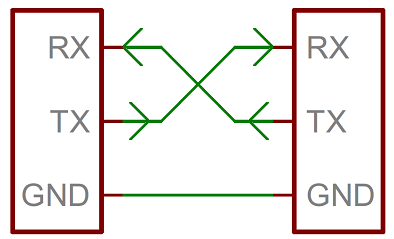
A serial bus consists of just two wires - one for sending data and another for receiving. On a simple serial bus communication network, the host has an RX (Transmitter) where it “talks” and an RX (Receiver) where it “listens”. One board/processor receives data individually from the host through the TX line and sends data back via the RX line.
![]()
A recurrent mistake for beginners is to connect wrongly RX to RX and TX to TX, when the correct is the TX (transmitter) to be connected to the RX (Receiver) and the other way around, RX to TX. Otherwise, putting it in a simple analogy, you are connecting two “talkers” where no one is listening, and two “listeners” when no one is talking.
Because serial ports are asynchronous (no clock data is transmitted), devices using them must have clocks (with almost the same rate) and follow a pre-agreed data rate. Another setback is that it is suited best to connect two, and only two, devices. Adding more devices would require normally cause bus contention (where two devices attempt to drive the same line at the same time).
Even if you decide to connect multiple boards via SPI (Serial Peripheral Interface), which uses separate clock and data lines, with processors taking turns to transmit their data, it requires too many lines / pins, 4 per “slave” processor and one additional I/O pin on the master.:

What is I2C?
Sparkfun has an comprehensive page dedicated to I2C communication here.
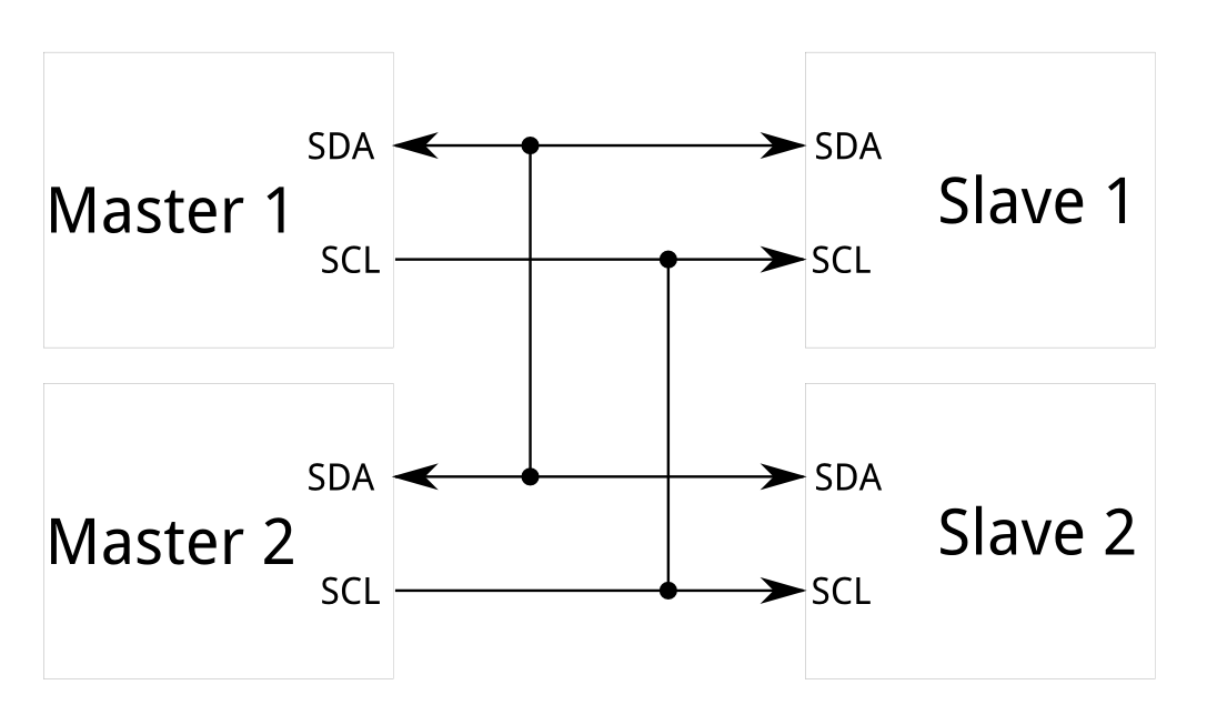
Is a standard synchronous (with the support of and external clock signal) protocol for in which you have only two wires:
- A data line (SDA - D is for Data) and a clock line (SCL - C is for clock), allowing multiple “slave” digital integrated circuits (“chips”) to communicate with one or more “master” chips.
Connecting my Fabduino and my Hello Board to talk via the I2C protocol
I had pre installed the Arduino Wire library, which allows you to implement I2C and TWI (Two Wire Interface) communication between Arduino boards. It emulates the functions and behaviours of Arduino Serial.
Since I also needed to work with my previously made Hello Board, which has an ATTiny44 micro-controller, I used the TinyWireM library by Adafruit which adapts the same commands of Wire to the SCK and SCA pin of every board in the Atmel ATtiny family.
Using the library examples as a reference, I had to write two programs for the two boards: One for my Fabduino and one for my Hello Board.
The Hello Board acts as the master and sends a character increasing in value every second:
TinyWireM.beginTransmission(1);
TinyWireM.write(x);
TinyWireM.endTransmission();
x++;
While the Arduino reads the communication and sends it to the serial port:
void i2cRead(int bytes) {
  char c;
  while (Wire.available() > 0) {
    c = Wire.read();
    Serial.print(c);
  }
  Serial.print("\n"); //newline
As mentioned above, addressing has to be made for the slave:
Wire.begin(1); //assigned slave address 1
And the slave has to call receive a transmission from a master:
Wire.onReceive(i2cRead);
The complete code for the Hello Board (Master), was the following:
#include <TinyWireM.h>
#include <USI_TWI_Master.h> //library with many define used by TinyWireM

int led = 7;
byte x;

void setup() {
TinyWireM.begin(); //no address required for master
pinMode(2, OUTPUT);
}

void loop() {
TinyWireM.beginTransmission(1);
TinyWireM.write(x);
TinyWireM.endTransmission();
x++;

}
The complete code for the Fabduino (Slave), was the following:
#include <Wire.h>

void setup() {
Serial.begin(9600);
Wire.begin(1); //assigned slave address 1
Wire.onReceive(i2cRead);
}

void loop() {
}

void i2cRead(int bytes) {
  char c;
  while (Wire.available() > 0) {
    c = Wire.read();
    Serial.print(c);
  }
  Serial.print("\n"); //newline
}
So, from the Arduino IDE I flashed both boards individually with their codes (“Fabduino” via FTDI and the Hello Board via my FabISP).
I connected them via the SDA (Fabduino “PC4” + Hello Board “MOSI” ) and SCK/SCL (Fabduino PIN PC5 + Hello Board SCK) pins of each, which were also connected to the 5V power source protected by a couple of resistors. They require power because, in I2C, the wires have to be always high unless they’re driven low by the controllers themselves.

Here’s a screenshot of the serial monitor and the increasing characters:

And a video of the working network:
You can find more information about Networks on Neil’s class here