
This work is licensed
under a
Creative Commons
Attribution-NonCommercial-
ShareAlike 4.0
International License.
This week's goals are the following:
Documented what you learned from reading a microcontroller datasheet.
What questions do you have? What would you like to learn more about?
Programmed your board.
Described the programming process/es you used.
Included your code.
Individal assignment: make your board do something.
First thing to do: first pick an architecture.
Read the data sheet of a microcontroller.
MicroProcessors are sorted by size.
Processor Architecture Families:
- AVR (the one we will use in class). Cheap, great software support and peripherals
- Arm
- Logic
- MegaProcessor
We will use the software AVRU and the FabISP programmer that we made on week 5. The main language we will use C and Arduino C++.
This week we had two workshops at FabLab Barcelona. Their main goal was to give us some basic knowledge about the intersection between electronics and programming. Find below my notes on the information that I found to be the most relevant.
Usually, the family of the processor goes at the end of the name. AVR is manufactured by Microchip formely Atmel.
Octo part: search engine for electronics parts.
When you create your own board, you have to pick your microcontroller but you also have to select the packaging.
The ISP Programmer is connected to the board through the pins Miso, Mosi or Ground. Certain pins can read analog inputs but not all of them.
We will mainly use Arduino environment to make a light blink.
Arduino has 13 pins to be used as either digital inputs or outputs. It has 6 analogue pins. Depending on whether you are using an analogue or digital pin you use the functions digitalRead and digitalWrite or analogueRead and analogueWrite.
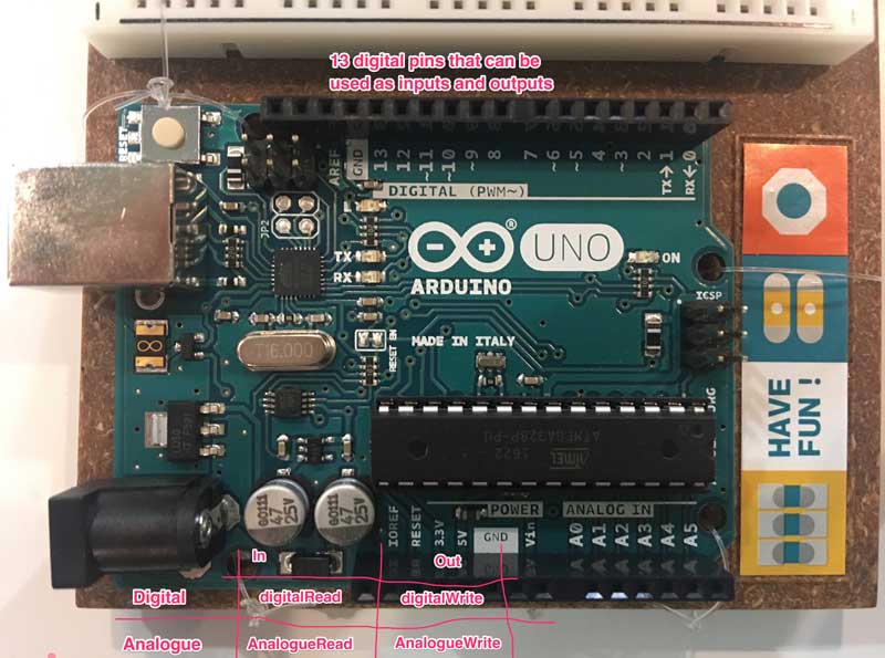
The main difference between Analogue and Digital pins is that digital pins can only send or receive binary information which in the arduino language is written as HIGH and LOW. Analogue pins can return specific values ranging from 0 to 1023.
First we need to load the ATTiny44 library from http://highlowtech.org/?p=1695.
A manufacturer's datasheet will never provide you with the Arduino numbering. That can be found in Pin Out diagrams such as the one below:
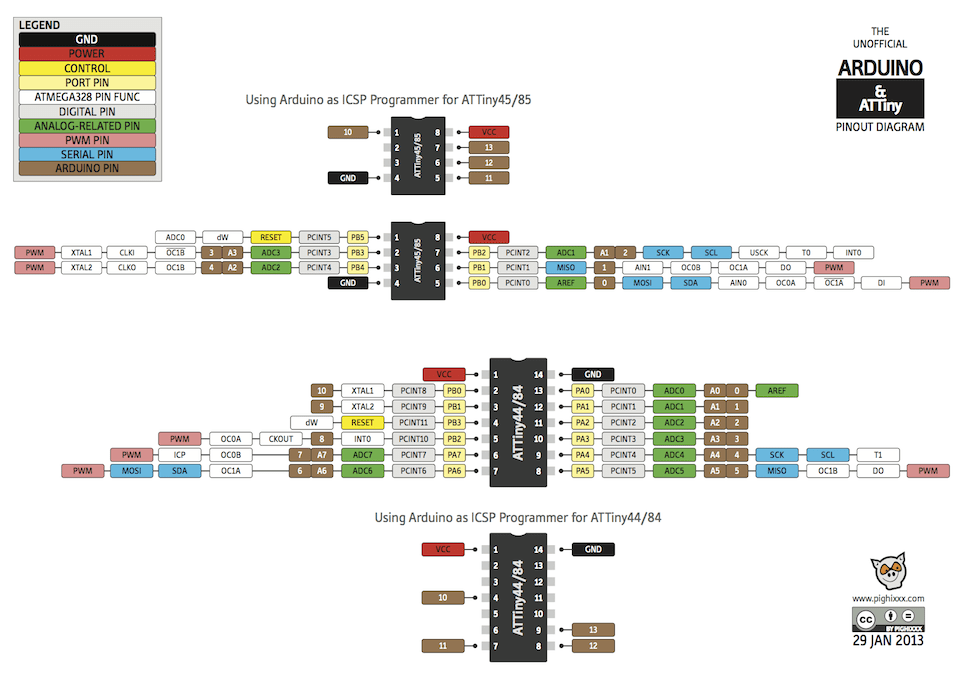
Image source: http://www.getmicros.net/programming-an-attiny44-using-an-arduino.php. (That site has a great tutorial on programming an ATTiny44 using Arduino, by the way.)
The arduino language is based in two main functions.
The setup function with the following syntax: void setup()
The run function with the following syntax: void loop()
Arduino then turns the program into real AVR C by making the connections below.

Image source:http://www.nongnu.org/avr-libc/.
In the "real" C language, there are 8 pins per port. A. PB is port B. Each pin can either be an iput or an output. If it's an input, then the DRRA switch (direction register for A) set to 1. If it's an output it is set to 0. Macros: they replace a certain operation by a given name. Macros can be identified because they start with #define.
If you can't find a function in Arduino, it means that it's an AVR function)
The hierarchies of code are as follows:
1. Sequence: Step by step actions one after the other.
2. Iterations: How many times you repeat each action. Mix the mixture 20 times.
3. Parallel: Actions that take place at the same time.
4. Conditional: If the water is boiling pour the content into the water
If not, wait.
5. Data: Number of guests.
6. Operators: operations you can do within the code. 2 spoons x guest.
7. Events: When water is boiling, turn off the fire. When x happens, do y.
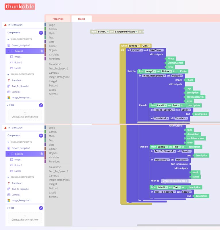
When we got to this part of the workshop, we played around with the programming language Scratch. We used
Thunkable, a great tool to get a visual sense of how programming works.
See below a couple of screenshots summarizing my work with the interface:
I also downloaded an iPhone app called Tickle.
It uses the visual interface of Scratch to teach users how to make their own video games. Here is a screen video of me playing around with it :
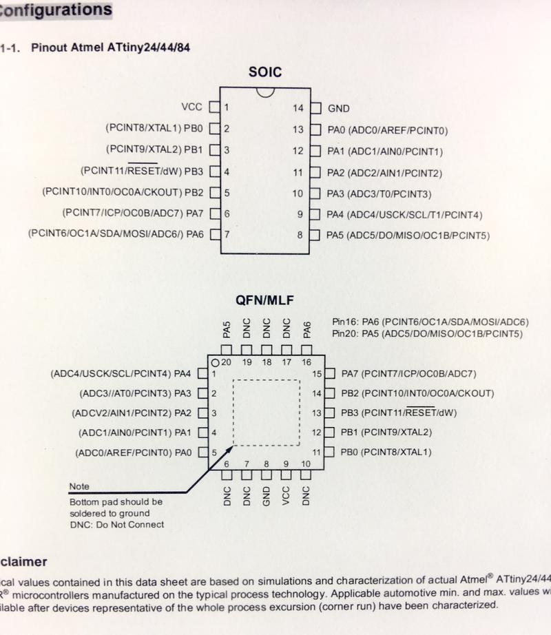
The ATTiny24/44/84 family is made up of the following pins:
The CPU core runs on the AVR architecture. Find below the block diagram: image of the block diagram
The ATTiny24/44/84 chips have three different types of memory: data memory, program memory, and the EEPROM Data memory. The data memory has two parts - each memory is made up of 8 switches (or bits).
The program memory is a reprogrammable flash memory that stores the program. It can endure up to 10,000 write/erase cycles. The flash memories
can store up to 2/4/8 Kb sized programs. It receives AVR instructions that are 16 and 32 bit wide.
The chip contains four different clocks: the CPU Clock, the I/O Clock, the Flash Clock and the ADC Clock.
The internal oscillator is the default clock and it runs at 8mHz.
Diagram of the Memories and the EEPROM and explanation of what burning the bootloader means. This concept was hard to grasp. The first paragraph in this tutorial made it easier for me.
Towards the end of the datasheet, you have a diagram of the component.
This week my progress was completely hindered as I realized that installing the X-Code program on my laptop did not fixed anything as the FTDI ports had stopped working again. However, as I knew that programming was a key aspect of my this week's assignment, I tried a couple of arduino tutorials using my ArduinoUNO and the breadboard.
Once I was able to fix my FTDI ports during week12, I came back to programming my Hello board. Based on the skills learnt during the week 8 in-class worskhops and the information gathered from the ATTiny44 datasheet microchip, I provided the steps to upload two different sketches to my hello board.
1. Connect the FTDI cable to the computer by making sure the ground pin is properly connected to the board's equivalent.
2. Burn Bootloader to make sure that there are no issues with the board's traces and soldering.
3. Load the Blink sketch from the Arduino IDE menu by going to File -> Examples -> 01. Basics -> Blink.
4. In the sketch, make sure you replace LED_BUILTIN with the pin number your LED is connected to. In my case, this is pin 7. Therefore my code will read as follows:
 void setup() {

  pinMode(7, OUTPUT);

}

void loop() {

  digitalWrite(7, HIGH);

  delay(1000);

  digitalWrite(7, LOW);

  delay(1000);

}
5. Alternatively, you can also previously define LED_BUILTIN as always associated to pin 7. In that case, we don't have to replace it with 7 every time. In that case, the code would look as follows:
#define LED_BUILTIN 7

  void setup() {

  pinMode(LED_BUILTIN, OUTPUT);

}

void loop() {

  digitalWrite(LED_BUILTIN, HIGH);

  delay(1000);

  digitalWrite(LED_BUILTIN, LOW);

  delay(1000);

}
6. Connect the programmer to the 3X2 pin header by making sure the black cable of the programmer matches the ground in our board.
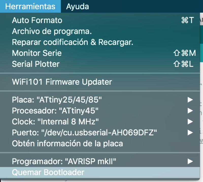
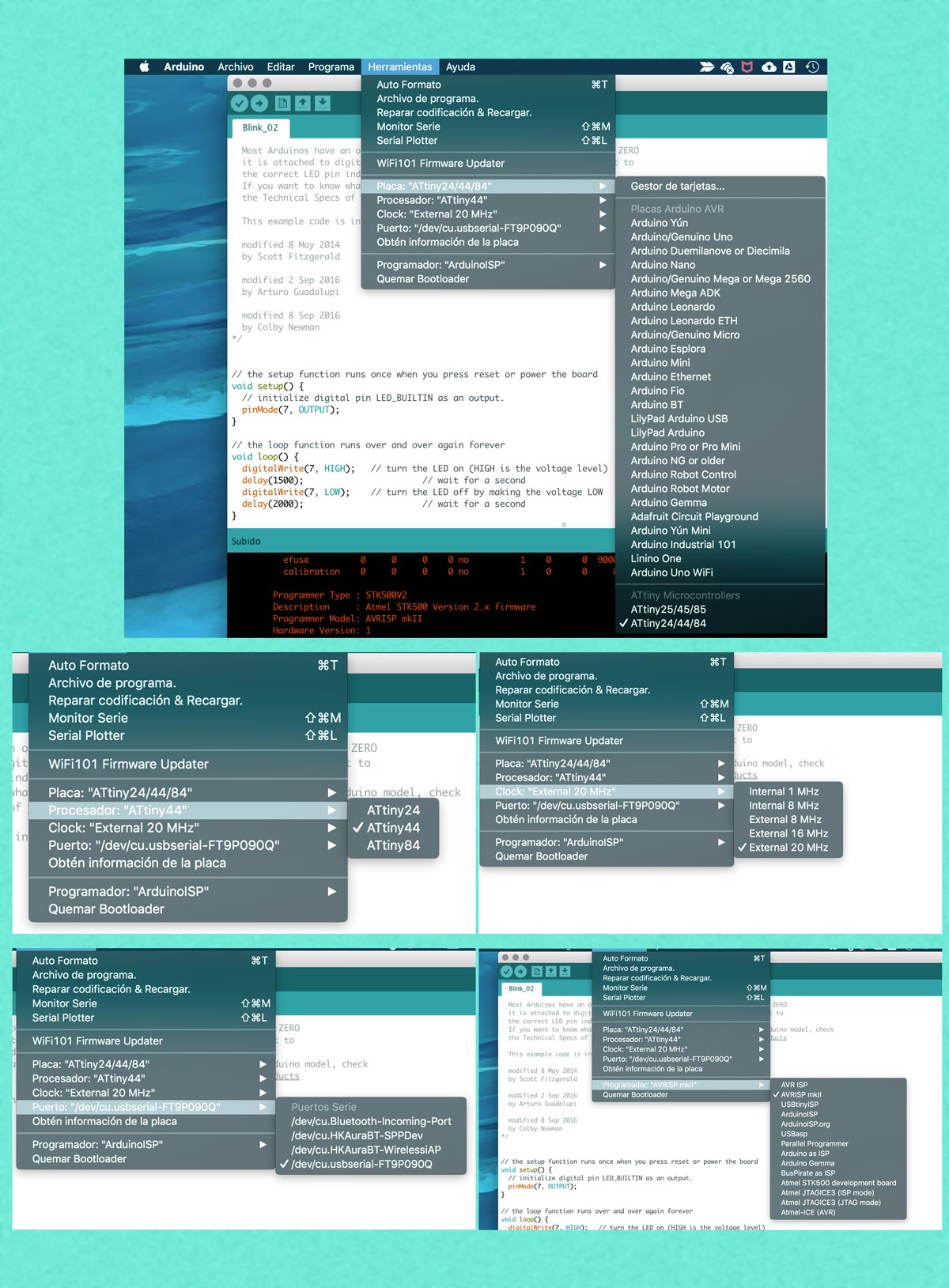
7. Then make sure that you select the right port, microcontroller, clock and programmer in the tools menu as seen below.
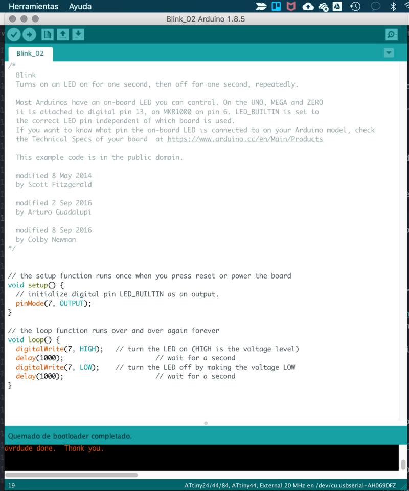
8. Finally click on the horizontal arrow pointing right.
9. If everything is properly wired and set-up it should all work fine.
For this sketch, I followed the same steps as above. But before that I made the following changes to the code.
1. I defined the variable of the button's pin.
#define buttonPin 10;
2. I initialized it as an input within the setup.
pinMode(buttonPin, INPUT);
3. I placed the code I wrote in 4.1. in a if...{...} else {...} statement.
4. Here is the result:
  #define LED_BUILTIN 7;

  #define buttonPin 10;


  void setup() {


    pinMode(LED_BUILTIN, OUTPUT);

   pinMode(buttonPin, INPUT);

 }


  void loop() {


  if digitalRead(buttonPin, HIGH) {

    digitalWrite(LED_BUILTIN, HIGH);

  } else {


    digitalWrite(LED_BUILTIN,LOW);

  }
This code was however not working.
5. I compared my code to the one in this arduino tutorial. The programmers declare in the loop a buttonState variable containing a digitalRead function as seen below.
void loop() {

  buttonState = digitalRead(buttonPin);


  if (buttonState == HIGH) {

    digitalWrite(LED_BUILTIN, HIGH);

  } else {

    digitalWrite(LED_BUILTIN, LOW);

  }

}
6. I realized though that what was wrong was not the fact that I was not using buttonState but rather that I had used
the Atmel's pin numbering instead of the arduino one.
7. This is the final code I ended up using:
  #define LED_BUILTIN A6

  #define buttonPin A3

  int buttonState = 0;


  void setup() {

    pinMode(LED_BUILTIN, OUTPUT);

   pinMode(buttonPin, INPUT);

   }


  void loop() {

    buttonState = digitalRead(buttonPin);


  if ( buttonState == HIGH) {

    digitalWrite(LED_BUILTIN, LOW);

    } else {

    digitalWrite(LED_BUILTIN, HIGH);

    }

  }
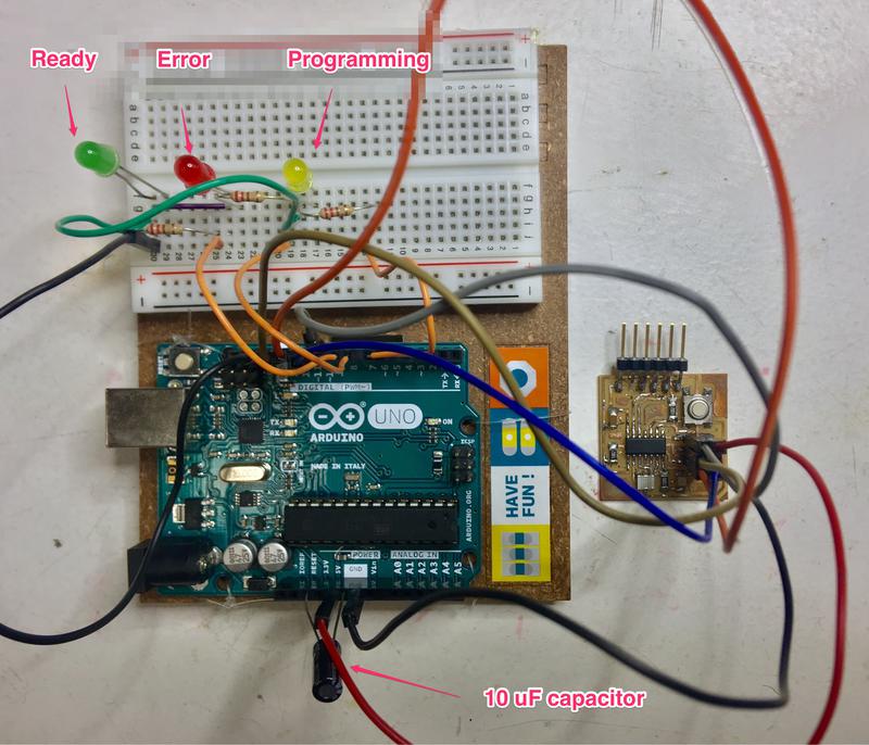
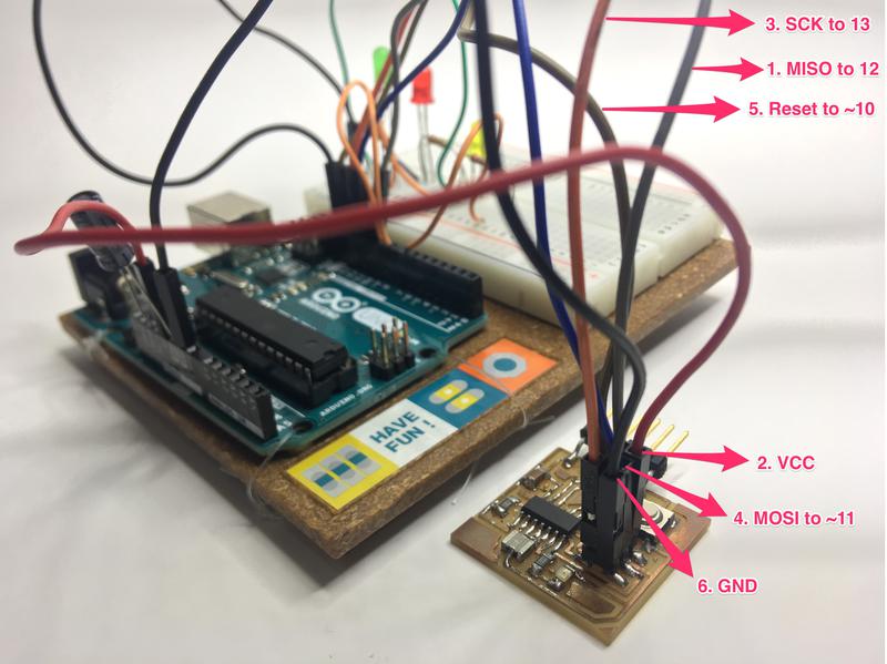
For this task I used the AVR programmer we have in our lab. However, the FabISP we made in class during week 5 didn't work. I decided to follow the
highlowtech tutorial on using Aduino as ISP. The image below available from Arduino.cc was very helpful when wiring the ISP header on my board to the Arduino Uno.
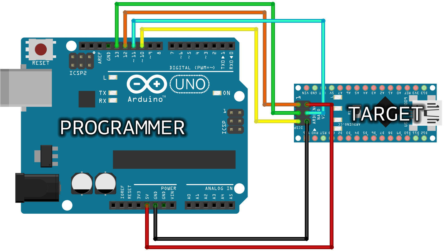 .
I also drew my own diagram in order to understand this further.
.
I also drew my own diagram in order to understand this further.
< sketch on arduino book >
Find below the results of the wiring:
However, the arduino website recommends to program the Arduino board first before wiring. These are the steps you have to follow:
1. In the Arduino IDE, go to File -> Examples -> ArduinoISP and open Sketch 11.
2. Tools -> Board: Arduino Genuino/UNO.
3. Port -> the one with (Arduino Genuino/UNO) at the end of the name
4. Upload the sketch
then, when connecting the Hello board via the FTDI cable make sure that you change back the Port to the one one the board is connected to. In my case it's cu.usbserial-FT9P090Q .
For programmer choose ArduinoISP.