This work is licensed
under a
Creative Commons
Attribution-NonCommercial-
ShareAlike 4.0
International License.
This week's instructions are the following:
Review the safety data sheets for each of your molding and casting materials, then make and compare test casts with each of them.
Design a 3D mold around the stock and tooling that you'll be using, machine it, and use it to cast parts.
The requirements are the following:
Explained how you designed your 3D mould and created your rough and finish toolpaths for machining.
Shown how you made your mould and cast the parts.
Described problems and how you fixed them.
Included your design files and "hero shot" photos of final object.
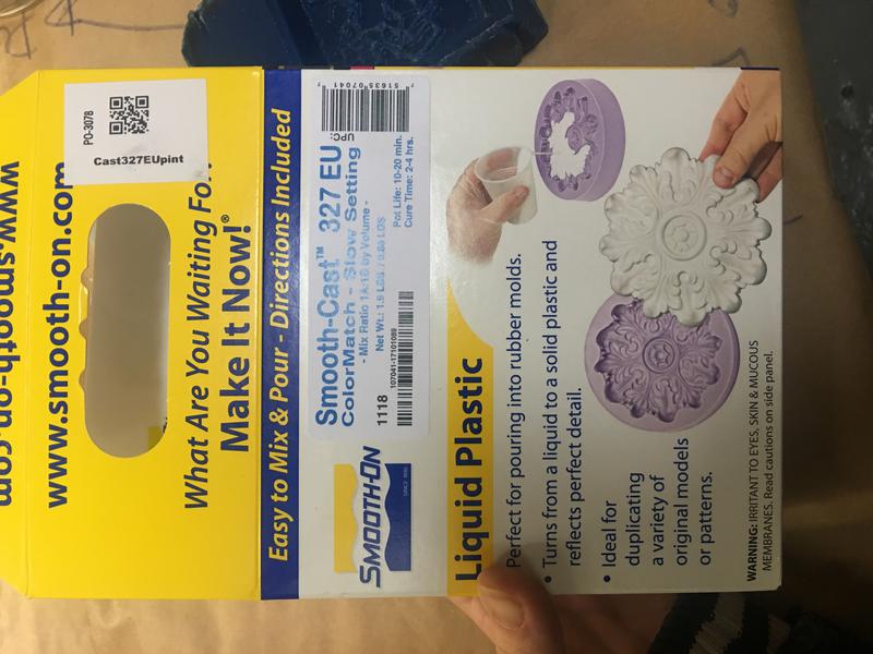
Different types of molding: among which is soft molding. Main vendor: Smooth-on and Blick.
machinable wax
alginates: casting from life
urethane
OOMOO silicone. Use OOMOO for the mold and Smooth-on for casting.
These materials have a timeline. Test them first. for the OOMOO you mix one part of the material and one part of the other.
Some other materials mix by consistency.
Super hazardous materials: Smooth-on Crystal Clear. Use protection gloves, goggles and mask.
The mold has to be machined. This time, we can use several different types of tools and not the same as the ones we used for our PCB millling.
Form X store specialist in molding and casting.
The walls of the mold should have a certaing inclination since by doing so the tool can reach deeper.
When casting the actual object, put a layer of the actual material over the mold and make sure it doesn't have any bubbles before pouring in the rest.
Do not start with the double sided mold as it gets too complex.
Maybe extrude one of the images of the fire: one of the ones in focus but of abstract strains. Work on blender. Look up how to extrude an image in tutorials.
I first created a positive 3D model of the object I wanted to cast: some abstract version of my carbon molecules. In the end, I couldn't extrude one of the photographs of the
soot of my apartment wall. So I ended up using the amorphous carbon trace I had created on Week 2 parting from the online model by Sydney VisLab 1998.
I extruded the drawing using Fusion 360 and gave different parts different heights.
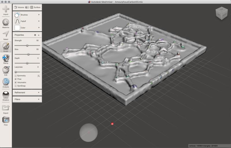
I converted the BRep object into a mesh and then shaped it by using the free autodesk's software Meshmixer. I then I used the
fillet tool to get rid of the sharp edges. I then used the sculp tool to make the object a bit more dynamic.
The links below were helpful resources through the process above:
Convert body into T-Spline in Fusion 360
Silli Saverio's Molding & Casting Documetation
Ferdinand Meier's Molding & Casting Documetation
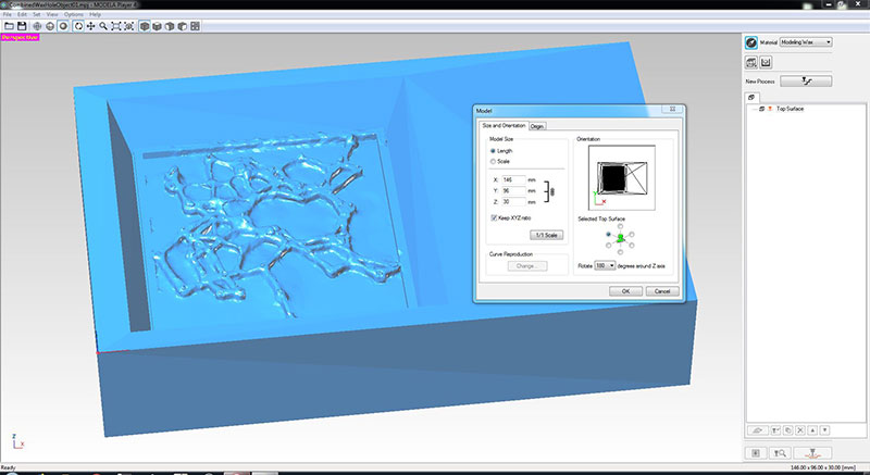
I then exported the mesh and placed it back into Fusion 360. There I created a rectangle matching the size of my wax block (146mm x 96mm x 30mm) and placed my molecule model in there. Remember to create the walls of the mold to have a certain slope so that the mold can be easily removed. I exported the whole block as an stl.
.
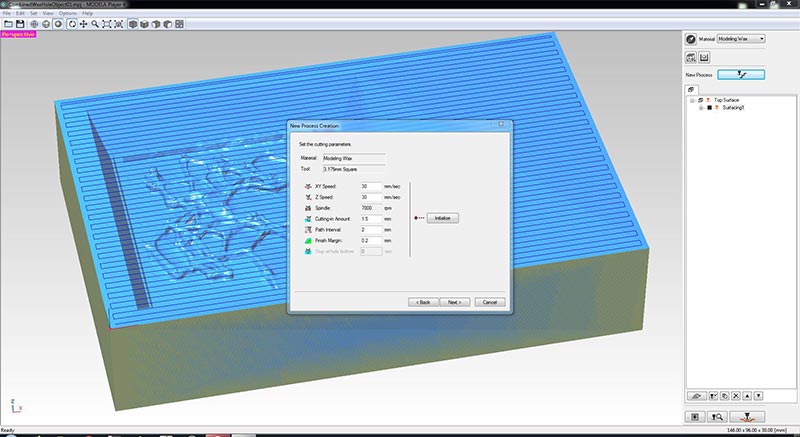
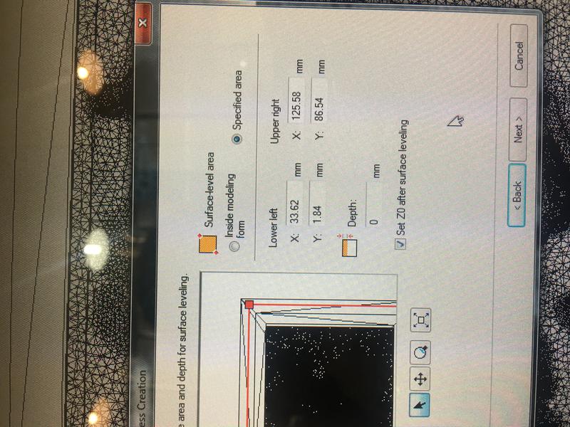
Once the design process is done, I set up the cutting strategy. This time, we used the same Roland SRM-20 mini-machine for shaping the wax instead of a PCB. I then imported the .stl into Roland's CAM software called Modela Player 4.
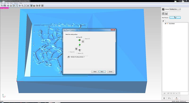
It is important to understand that this is a three part process: First goes the surfacing, roughing and then the finishing.
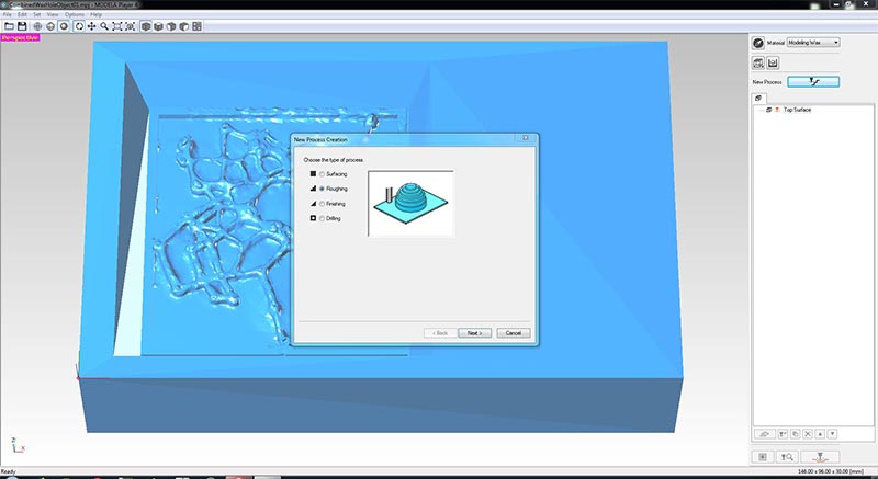
1. The surfacing pass entails running the machine along a zigzag path along the upper surface of the wax block to make sure it is flat and smooth. I used a 3.175 mm tool:
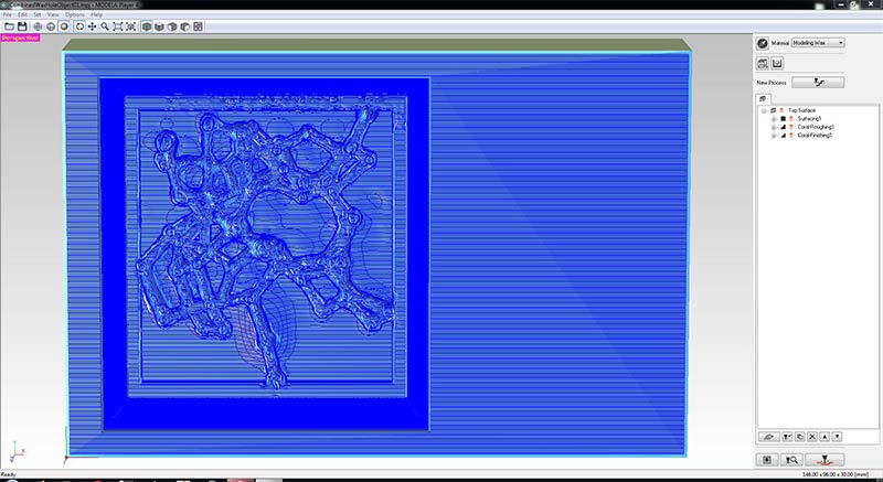
2.The roughing is the process in which the machine's tool removes most of the extra wax by making a rough approximation of the design.
For this I used the same tool as for the surfacing.
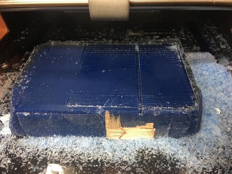
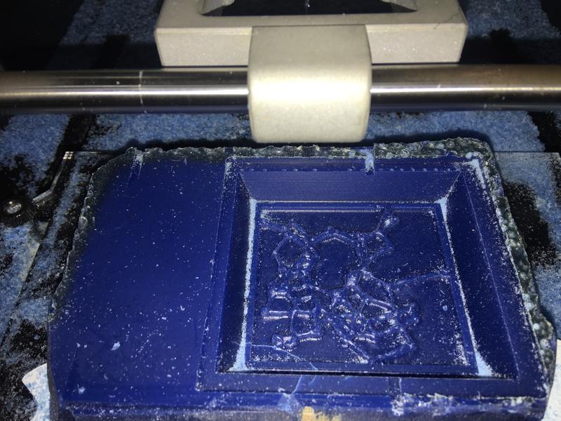
3. The finishing is the last step. With a thinner tool of 0.8 mm diameter, the machine carves out the details of the design.
It was a pretty slow job:
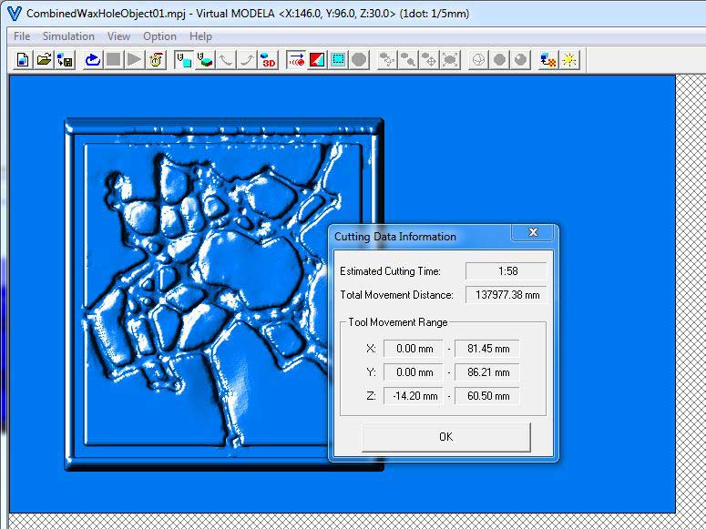
I had to run it two different times. The first time I had not set the home coordinates properly and the x and y
axis had been switched. The machine started milling in the center of the block, not leaving enough space for the rest of the design.
I then had to generate again the CAM strategy. This second time, I measured the z-home coordinate
before the surfacing pass. I immediately ran the roughing file and when it came to switching to the finishing, I realized
the error. There was going to be a bit of an offset. So then I measured the correct z-home coordinate and run the roughing again.
The machine followed the same path again, sometimes tracing in the air but I just let it run. This fixed the issue and I was able to run the finishing effortlessly.
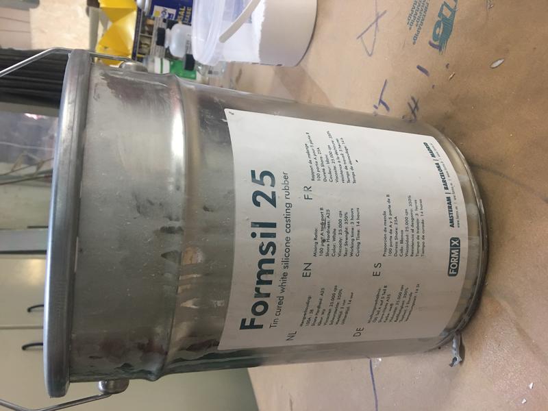
We used the two part "Formsil 25" for making our molds. Unfortunately, the Material Safety Data Sheet and the Technical Data Sheet are not available online and we did not keep a copy in our lab either. This material requires a catalyst and the silicone at a ratio of 5% catalyst to 100% silicone.
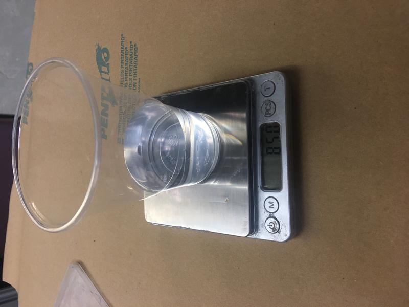
1. In order to determine the quantity of silicone needed, I first filled my wax block with water. I then weighed the amount of water required to fill my design: 85.0g . This means that I will need 85.0g of silicone and 4.25g of catalyst to make my mold.
2. Mix thoroughly both parts and place under the vacuum machine to remove the air bubbles.
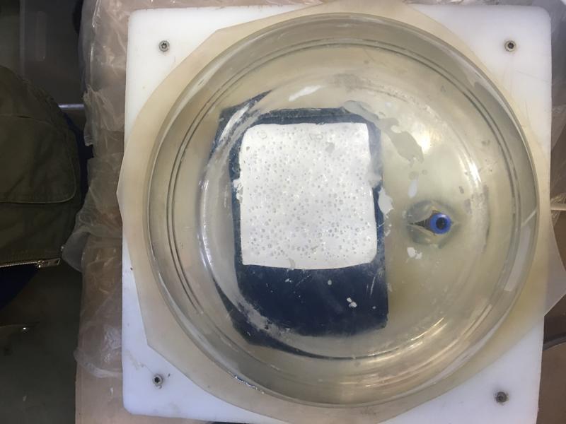
3. Before pouring mixture into the wax block, it is helpful to spray a removing agent in the cavity. Pour very slowly to minimize the appearance of new bubbles.
4. Place under the vacuum machine again.
5. Let it sit for 24hrs.
6. Remove from the wax.
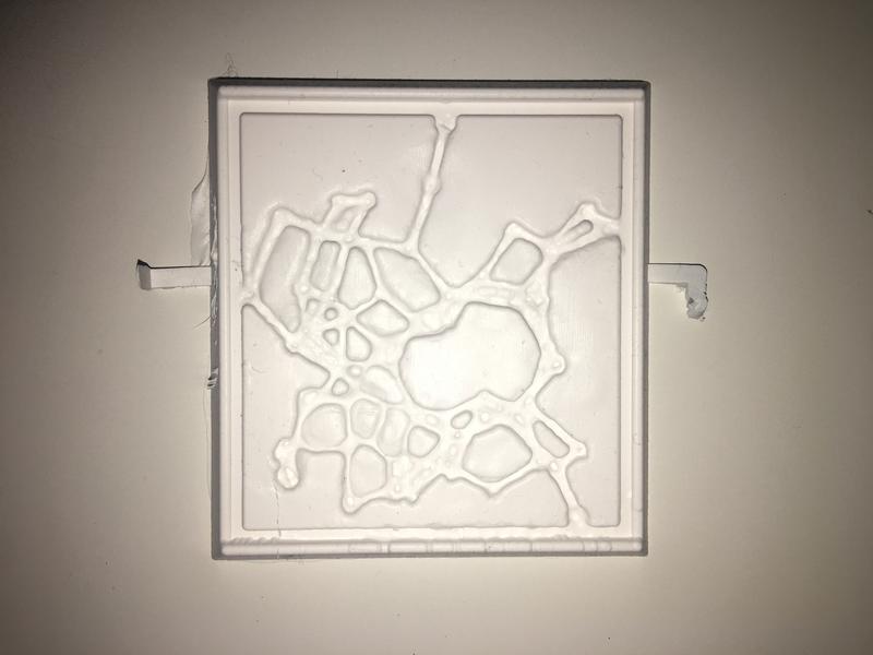
1. At this stage, I realized I had made a design mistake. I didn't realize that the heightest points in my object should be the border walls. Now my mold did not have enough volume to hold the casting material. I therefore built a surrounding wall with carboard and tape.
2. To cast the mold I used Smooth-On' Task 2. This is a two part liquid plastic compound. The mixing ration is 1:1 Part A and Part B.
Material Safety Data Sheet
Technical Data Sheet
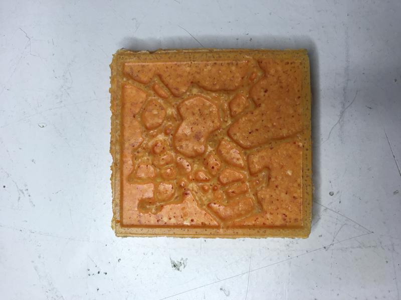
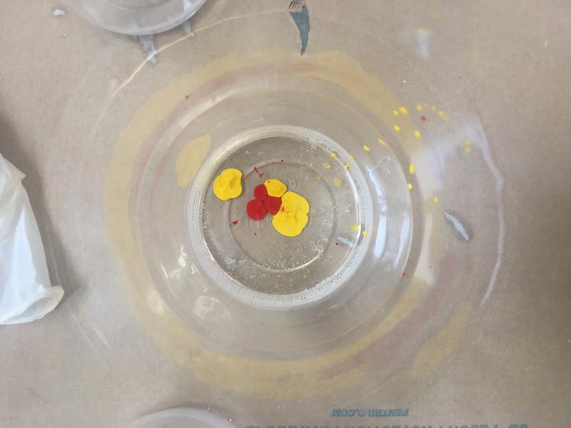
This material doesn't need to be placed under the vacuum machine. I mixed the two parts and then added a couple of droplets of color before adding Part B. In the datasheet of this chemical it does say that this plastic is appropriate for color. However, when I mixed the two parts the mixture started bubbling as if it were effervescent!
 3. I let it cure for 8 hours and then removed it.