This week the focus is - Computer Controlled Cutting, We were given inductions and tutorials in Laser cutting and Vinyl cutting. The main machines we are learning about and using here at the BCN fablab include:
Laser Cut - Multicam 2000
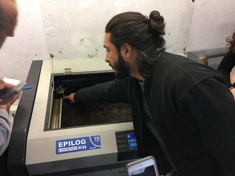
Laser Cut - Epilog Legend 36EXT
Laser Cut - Spirit
Vinyl Cut - Roland GX-24
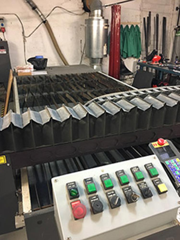 MultiCam 2000 Laser
 Epilog Laser
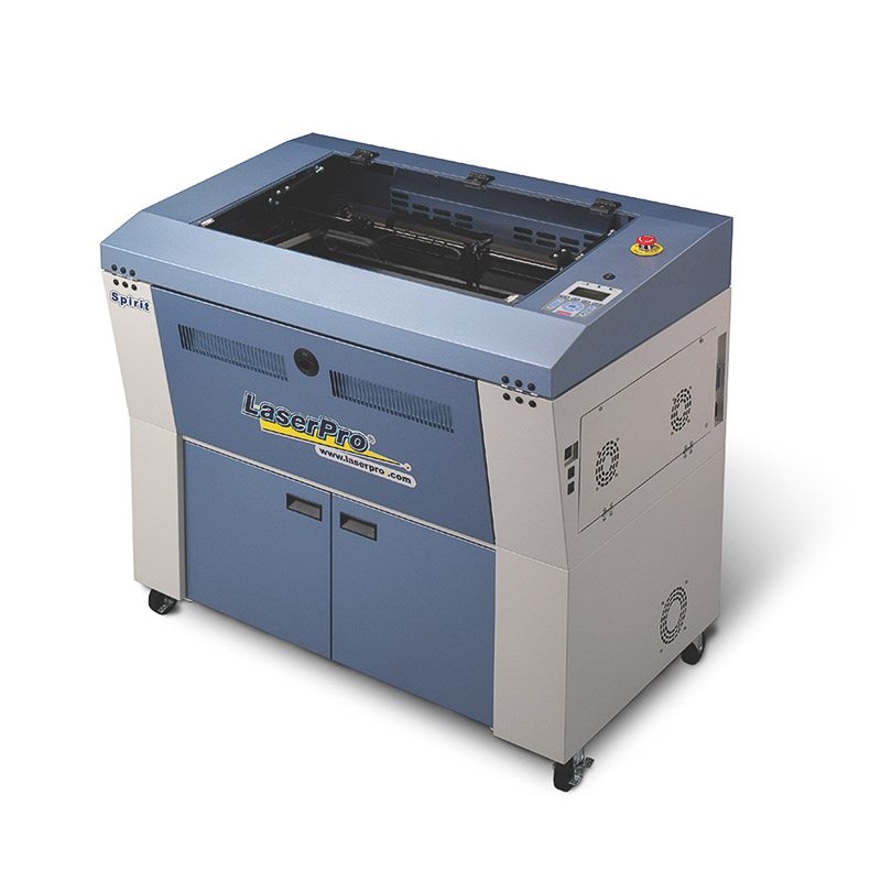 Spirit Laser
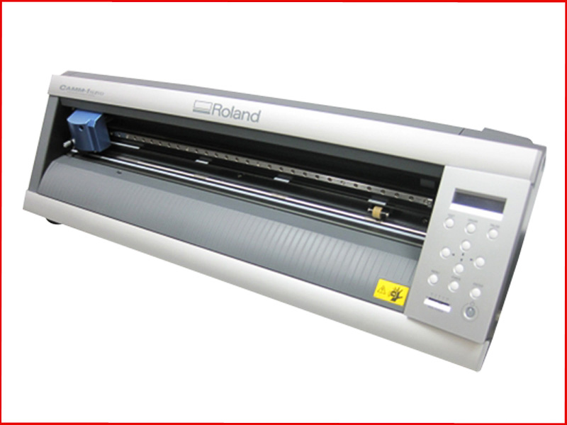 Roland GX24 Vinyl Cutter
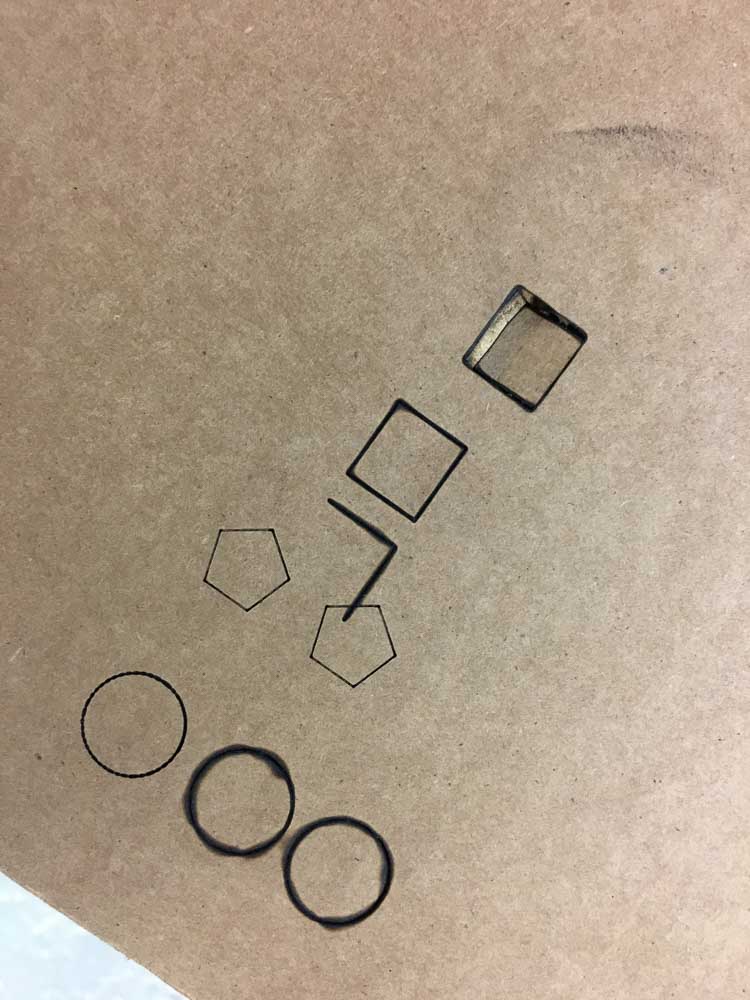
The first objective we did collaboratively as a group during our induction. The task was to make test-sample cuts on each of the laser cutters available in our lab. Primarily we used cardboard or plywood and scrap off cuts to begin with. We were encourged to practice adjusting the settings in order to cut cleanly straight through the material, or by setting-up to make engravings or etching cuts with text, line drawings or raster-based images.
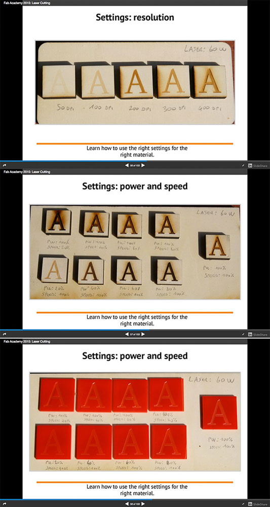
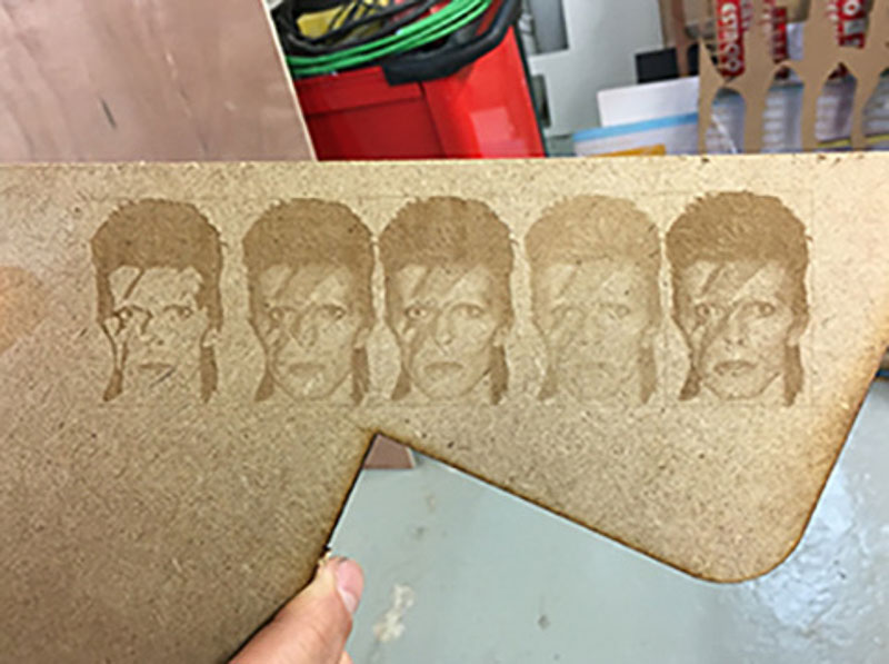
Different cuts and outcomes are primarily achieved by controlling the Power, the Speed, the Resolution and the Frequency of the laser settings. In order to give good consistent, clean and safe cuts it is very important to know the type of material you are working with. Measuring the exact thickness of the sheet that you will be cutting and knowing something about how it might behave as it is cut with the laser.
For instance Paper and Card will cut very quickly and easily and plastics like acrylic will cut like a knife through butter and can often be cut very effectively and fast on lower power settings, whereas thicker denser materials such as M.D.F or plywood will require slower speeds and more powerful cutting settings.
Not enough power and you won't cut the material out neatly. However these lower power settings can be adjusted and tuned to give results for etchings or engravings. With too much power or slow speeds this may result in singed or burnt edges, or excess melting, and unclean cuts. Or worse, if left unchecked could result in a fire, damage to the machine or equipment, to oneself or others.
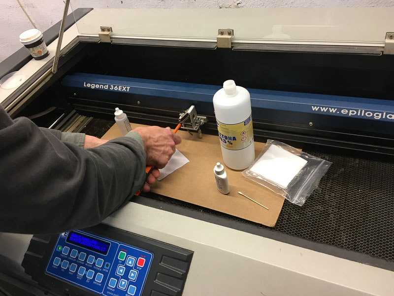 dirty build up on lense
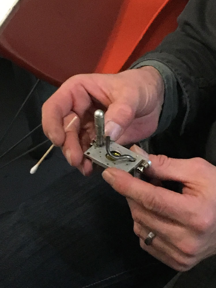 routine lens cleaning
It is of utmost importance to follow the correct safety measures when operating any machine in the workshop. Make sure you wear some form of eye protection, turn on any connected ventilation extraction and cooling that is connected to the machine and then machine itself. When in doubt reference the data sheet and instruction information from the manufacturer and workshop safety rules and advice - links above.
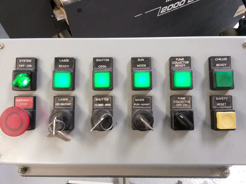 MultiCam - Power Up
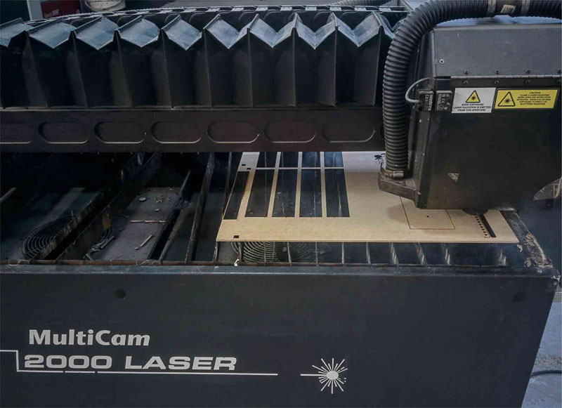 MultiCam - position the work and set 'x'y'z' axis origin home positions
Do all the safety and set up checks, have your material flat and appropriately fixed down or taped in position if needed, then proceed to set the home origin for the 'x','y' axis and then for 'z' alignmemt on the cutting bed.

 Set origin x-y and use tool to bring down z axis onto work surface.
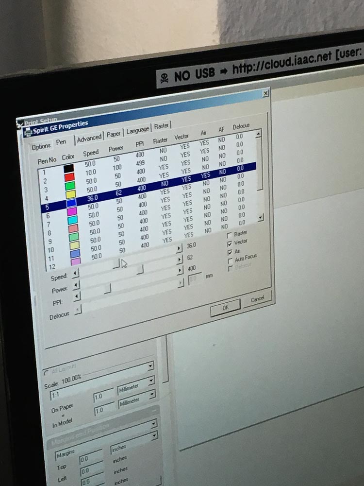
Then make adjustments as required for the Power, Speed, Resolution, Frequency and Pressure settings. The initial guideline data for these settings can be found by referencing here:
Barcelona fablab laser parameters document.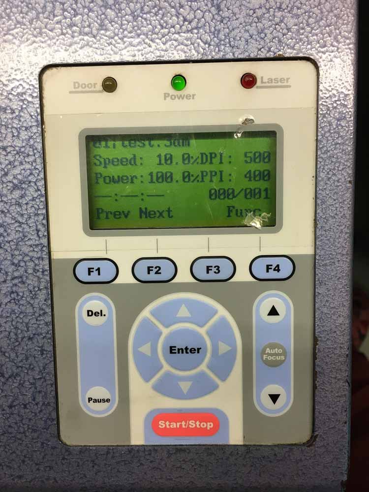
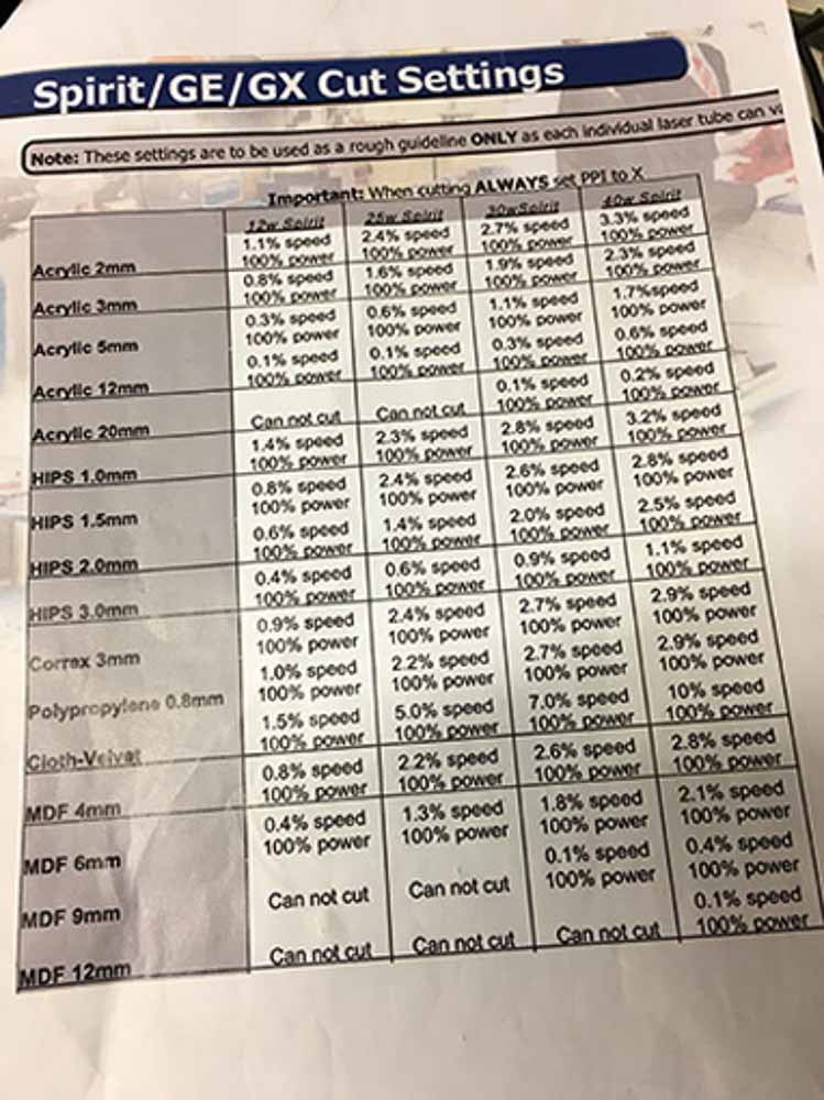
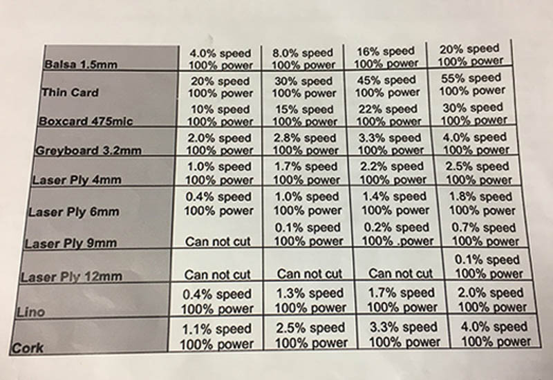
Using these documents we can find the expected values when cutting common materials in different thicknesses for the specific machines in our lab. With each of the lasers you can define a small test cut pattern allowing you to quickly and easily check results and make adjustments when setting up. Further tweaking and refining is made in the settings until you have the perfect test cut and are satisfied with the results.
If you have any doubts, as I did when setting the laser cut profiles; before you send your work to be cut you should ask one of the helpful workshop staff, in my case either Martin or Ricardo or fellow student, to double-check your settings. This will ensure you are confident to then proceed cutting with these machines. Remember to always make a test cut in an off cut of the same material you will be cutting so that you prevent wasting precious material and time and to minimize any potential damage to the machine or others. Once you know your settings and are ready with your material set up you can then send your file for your parts to be cut.
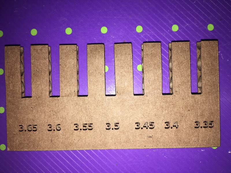
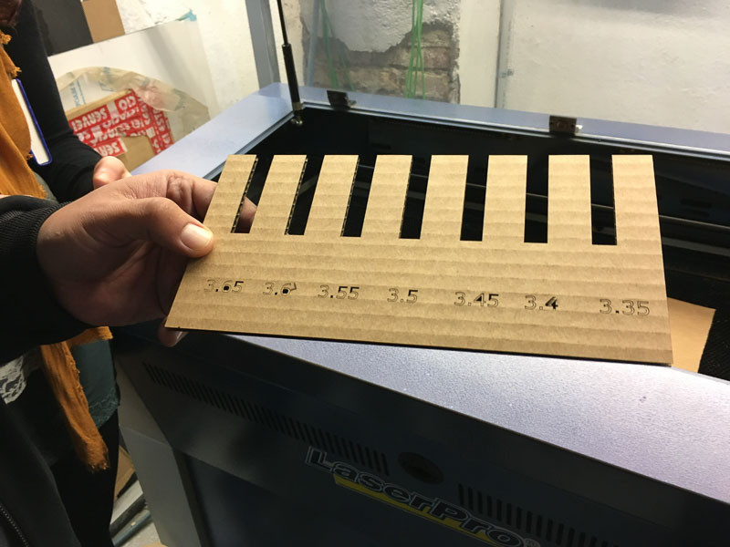
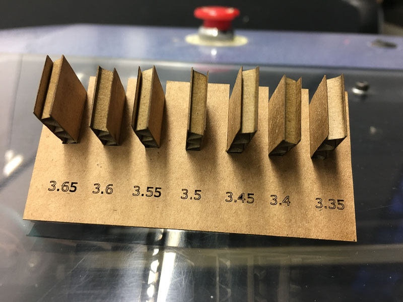
Test cuts are very important; firstly to indentify and calibrate our laser settings in order to make a clean cut through the chosen material and thickness. and Secondly graded tolerance cuts are also neccessary to further test fine tune machine accuracy for the job in hand, and then to account for these tollerances by making changes and adjustments to our 2D design files. These kind of tests are essential to ensure the correct fit of male and female push-fit parts, features such as holes, slots notches or noggins in our design, such assemblies will only come together nicely and snugly if the tollerances are correct.
As with all cutting processes there is a small amount of material removed along the cutting line, whether by blade or beam - in this case it is blasted out, burnt up and vaporised into thin air by the laser beam. This width of material is known as laser 'Kerf'.
We need to take account of this thickness of removed material. When nesting a series of parts on a sheet for cutting, to know how close together can they be, and also to allow programming for the interior and the exterior paths to be cut accordingly. So that the machine knows paths are to be cut half of this Kerf-width outside the part, and then inside of any cutouts and holes which are to be removed, leaving a dimensionally accurately cut part to the 2D drawing.
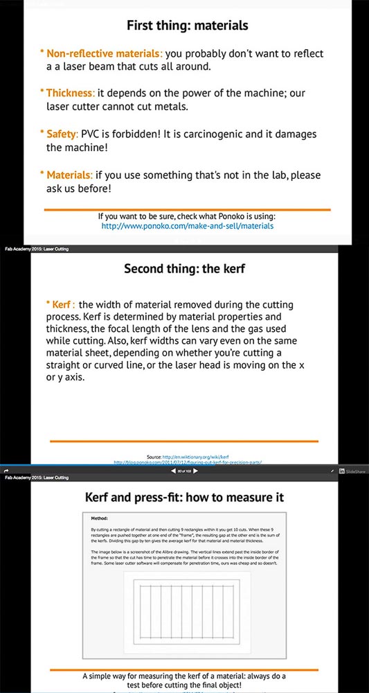
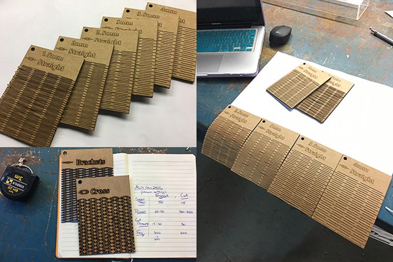
Our first test cuts were making samples with varied slot sizes incrementing in 0.05mm from our stock 3.5mm thickness card. Then measuring and testing the clearance and fit of inserted material to find the correct tollerance to give a snug joint.
Different materials in different thicknesses will obviously each have different properties and therefore would need testing separately. Other more minor factors also have an effect on the tollerance, accuracy and output of a particular machine. Things such as the atmospheric temperature and pressure in the location and on the day you are cutting, minor discrepencies in the quality and composition of stock raw material, and the overall working condition of the laser, the lens, the extraction and cooling, and other working parts of the machine. This is why a test cut and calibration before each job is so important. The parameter guideline sheet linked above is a good starting point when adjusting and setting up for a new cutting job. We have now acquired a good initial knowledge about safety and operation of the laser cutters. We have an understanding of the design rules and are aware of the different variables and settings that need defining. And have more idea as to the accuracy and scope for manufacturing potential that these machines have.
The second task was to cut something using the vinyl cutter, such as sticker to be used directly, or a template for stenciling or screen printing. It could even be used to make a folded net cut-out using a more rigid thin material for a 3D origami type construction, or could even be used to cut out traces for circuits using thin copper film or foils.
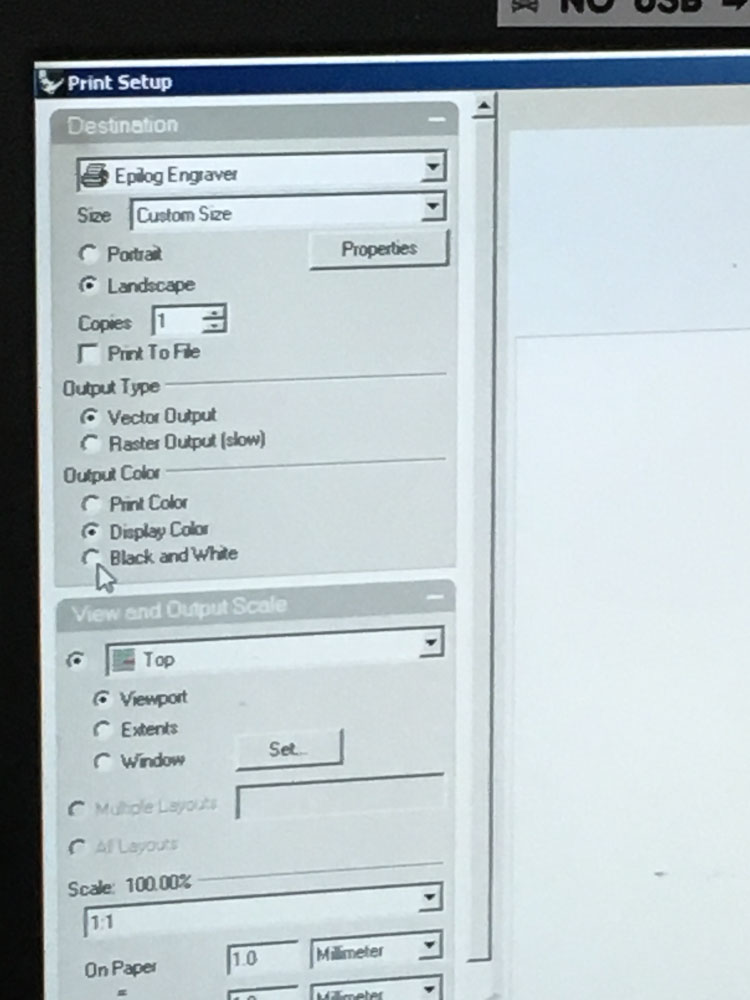
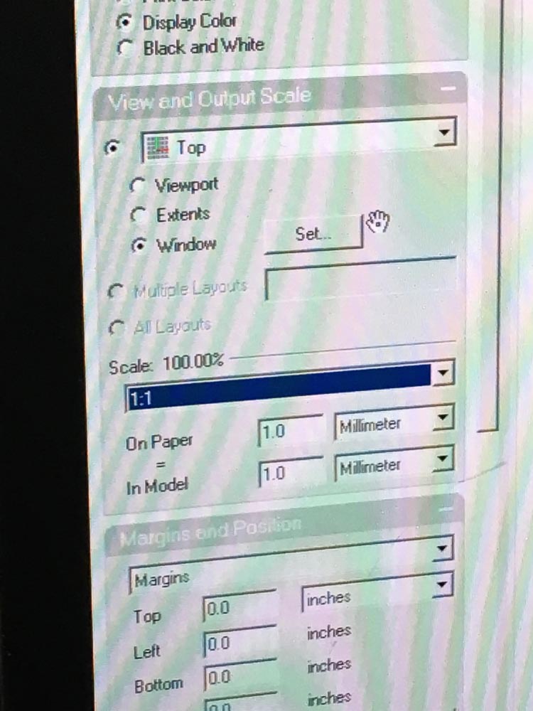
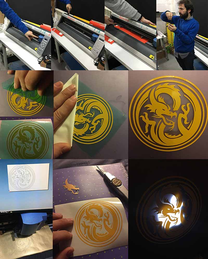
To send a file to the vinyl cutter involves creating a vector image with the outlines of your chosen design. I chose a dragon symbol as a bitmap image, one which was freely available in the public domain, I transformed this to vector paths and adapted the scale and shape a little in Inkscape before saving the output file as an '.svg'.
With the image file ready to export, you then need to select a piece of vinyl or a roll, turn on the Roland machine, check it has it's blade installed in the correct position. Begin to feed and align your vinyl into the machine, this can be done either from the front with smaller pieces and off cuts, or from the back of the machine typically from a roll. You must set the adjustable guide roller position accordingly with the edge of your sheet. Also importantly set the depth of the blade for the 'z' axis. You want it to cut through the top layer of vinyl but not through the backing sheet. I jumped straight on this machine after someone else had finished using it, and somewhat hastily sent my file to cut having negated to re-set the blade depth, and because I was using a different and slightly thinner gold vinyl material it didn't then cut completely through the first layer. So I re-calibrated and did a test on a new yellow piece to get this right. I then proceeded to cut out my dragon sticker. I applied it to my laptop by carefully peeling away the material I didn't want, and then sticking adhesive over the intended sticker to transfer it to the final surface in its correct position. See pictures of the whole process below...
The final stage of this assignment is to design, make and document a press-fit and fully parametric construction kit, accounting for laser-cutter kerf, which can be assembled in multiple ways... I have been looking at imagery and laser cut designs particularly the patterns created by the removed material in things like lamp-shades. And have been interested in laser cutting materials such as felt or leather to then make flexible fashion items. I was inspired by the following designs...
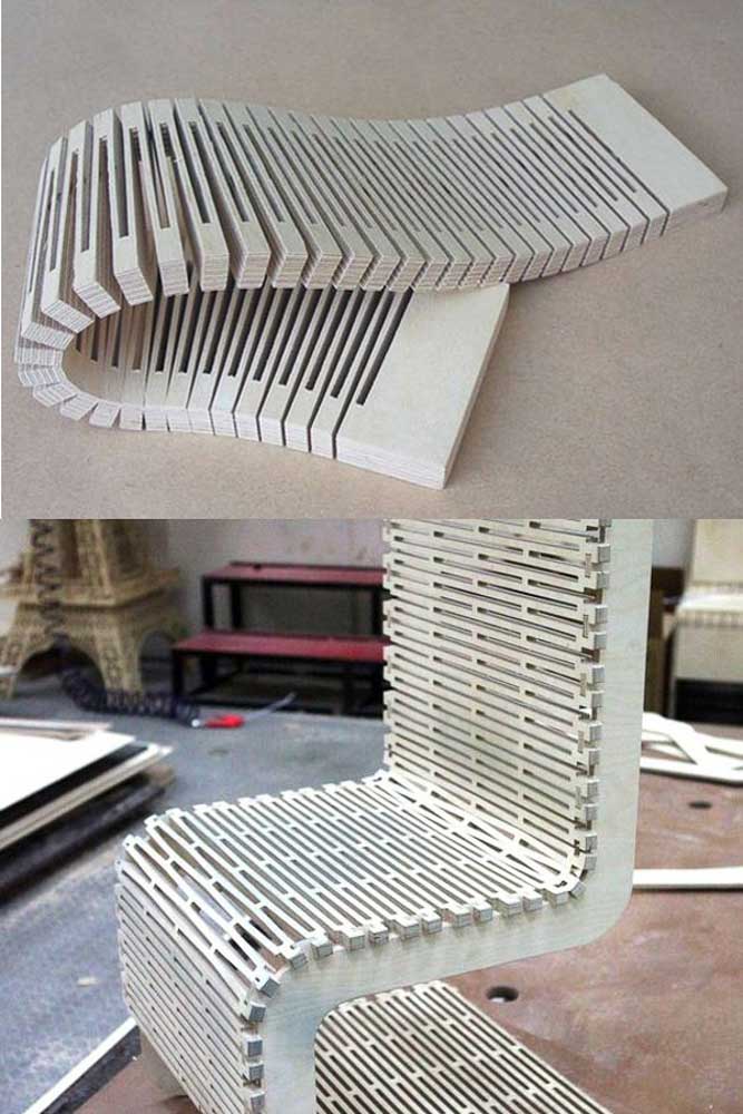
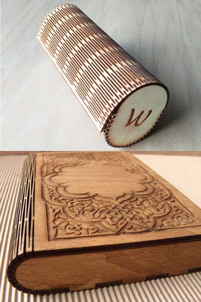
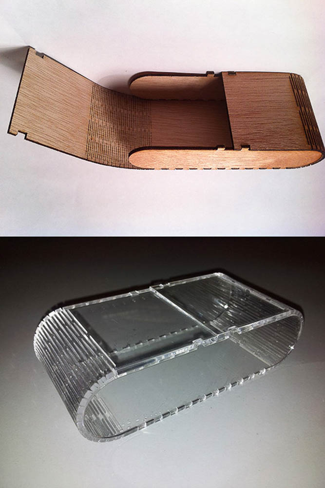
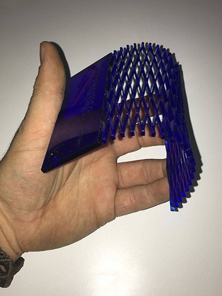
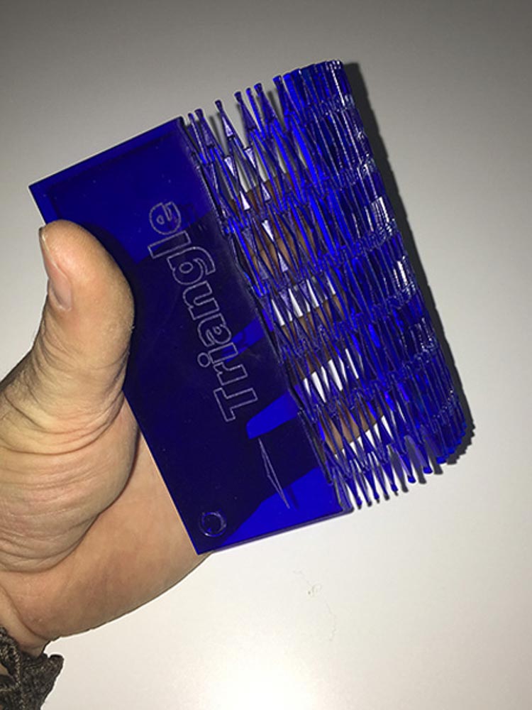
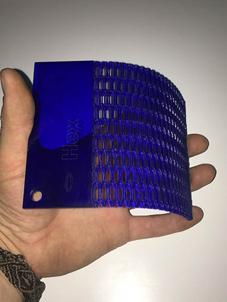
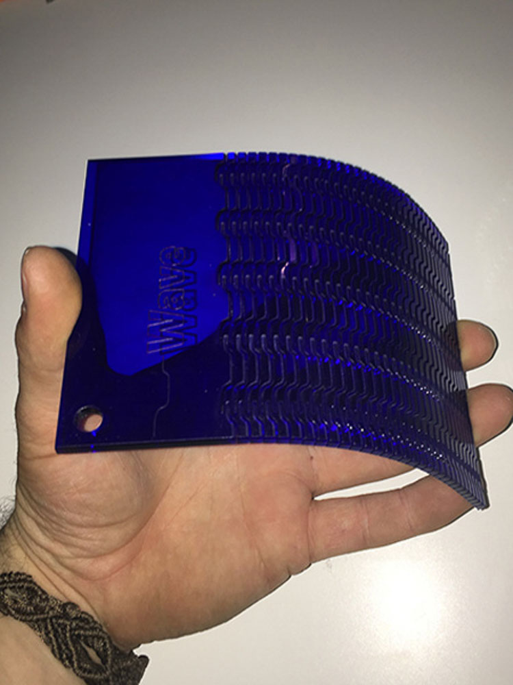
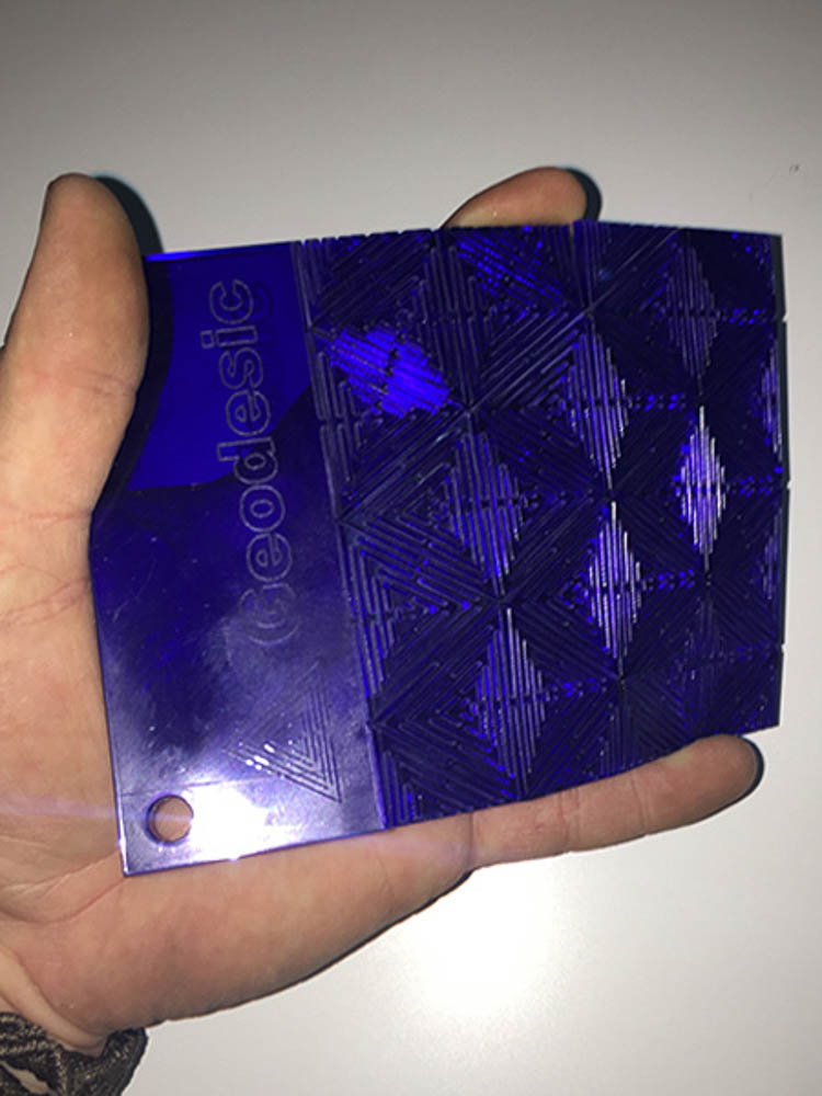
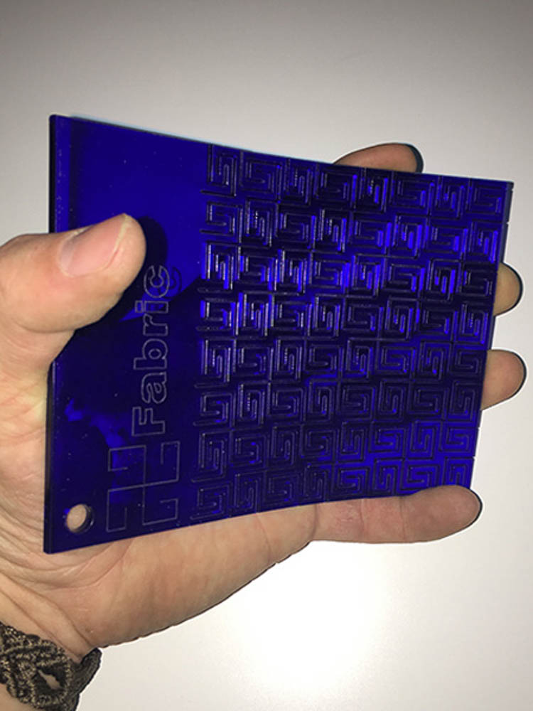
I was intending on creating my own box design for the storage of trinkets, tobacco or other such objects, similar to the ones seen above to fulfill the design part of this brief. I wanted to create something pocketable along the lines of a hip-flask kidney-bean shape. And I wanted to explore and incorporate flecturing, and make use of the kerfing patterns to create a living hinge. Enabling materials like wood and even brittle acrylic to have flexible properties. The part with the flecture has tabs along its edges with a press fit design to lock this bent surface into a final position around rigid end caps.
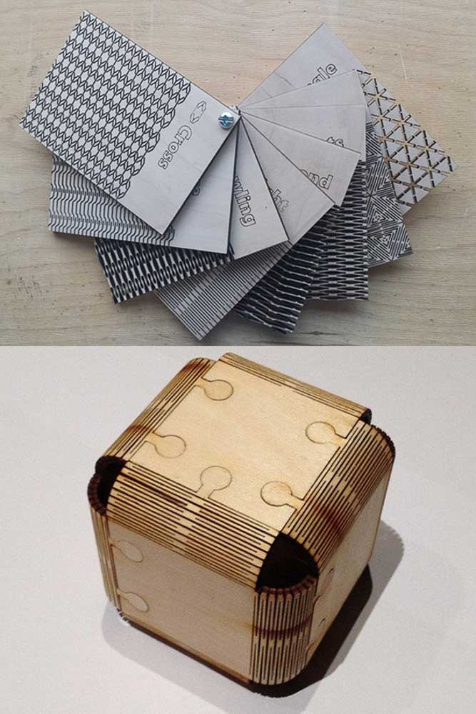
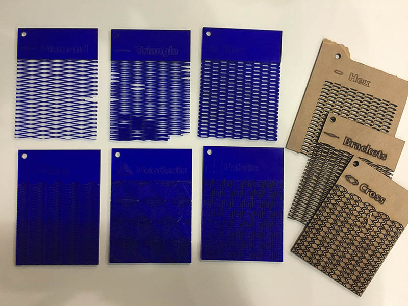
I spent a considerable amount of time researching these ideas and possibilities. I wanted to test the rules for different spacings and patterns to experiment with these flexible properties. I found and downloaded some suitable tests files or swatches from a cool company online Obrary they have many lovely designs and ideas suited for laser cutting:
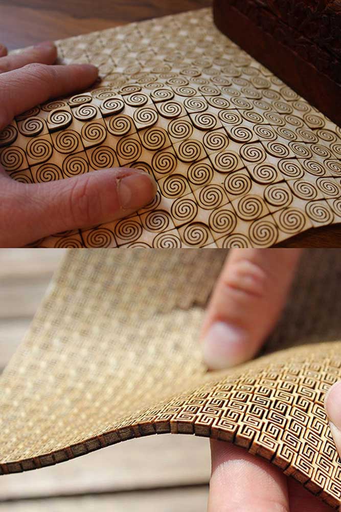
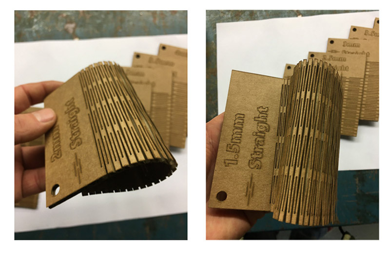
ObraryThen I played with these files and got to work making test patterns. I was learning much about settings and use of the large open bed MultiCam laser. I eventually ended up with some nice test pieces of live hinges in card, demonstrating the differing flextures of altering spacings between the cuts or having different repeated pattern elements.
I am also experimented using differing materials like Card, Wood and Acrylic. Obviously there are a lot of variables which can directly affect the outcome and properties of the flex. Material choice, thickness, pattern type, orientation and material grain, the separation between the cuts, and the width of the cut and the laser-kerf itself, all play a part that will affect the play, direction and amount of achievable bend.
I considered that it would be nice maybe as a future fab-project one could create a wall sample for common materials and their appropriate settings for each of the laser cutters to compliment our fab documents, but this would take some time and would be a lot of repetetive work.
In the end I spent so much time playing with laser settings and cutting these test pattern experiments with flexible hinges that I didn't really get around to finalise a push to fit model. I was even playing with some code which I found to try to generate a lozenge shaped box, with slots you only need to type in the thickness. For now the parametric design will be something I will need to revisit and complete properly at a later date.
Laser Cut - Kerfing live hinges