This weeks assignment is to build our own 'in-circuit programmer'... Que cosa?!, What is that!? and Why!?... You may well ask? Well indeed...A long time ago I studied GCSE electronics in school, and so I have a basic understanding about electricity, circuits and components, ohm's law and physics. Yet I have no idea about what's really going on inside these micro black boxes with legs-(pins) that we find on circuit boards everywhere, inside everything electronic these days. I really have no clue how they work, and how they can do all the amazing things that they are capable of doing.
So basically these microcontroller chips are miniaturised integrated circuitry systems, with certain capabilities laid out by their internal architecture and design. However these chips are shipped blank from the factory, with no information to identify what the chip should do initially. After having designed a new circuit-board we first need to flash the basic information to the microcontroller-chip, in order to be able to identify recognise and access it and then program it from a computer.
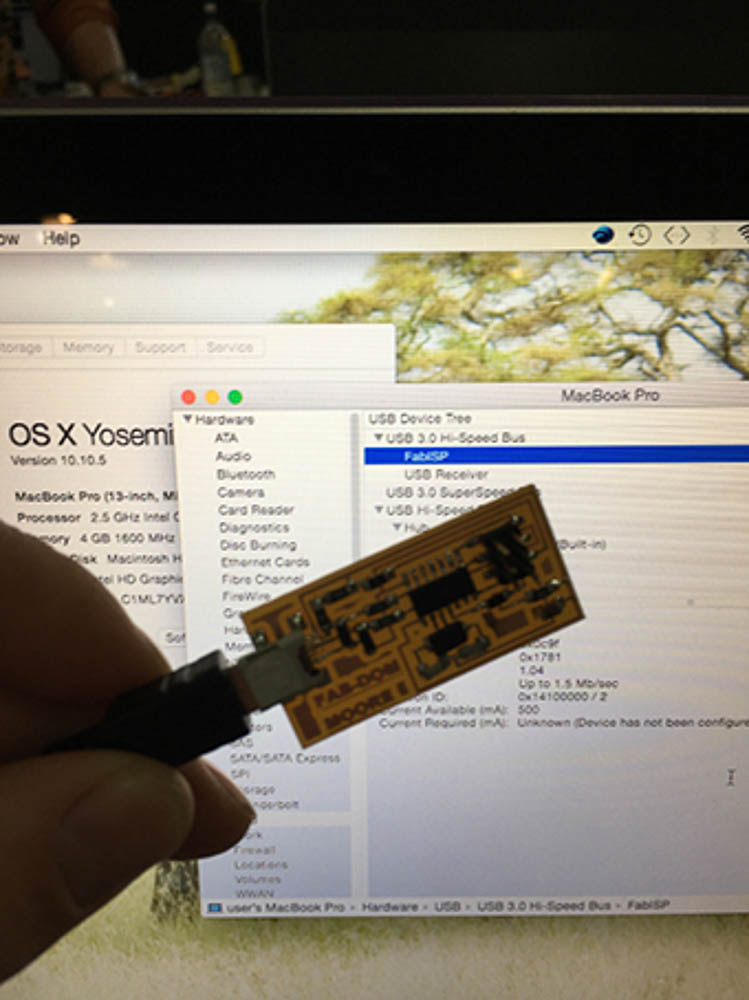
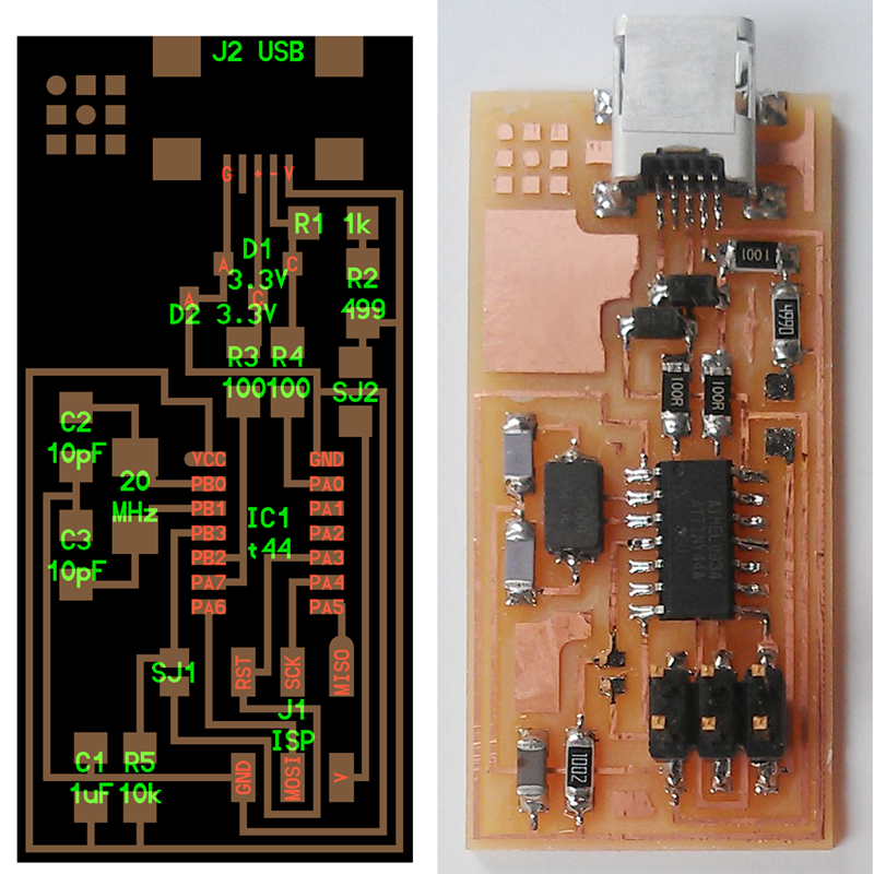
The FabISP is an in-system programmer board for the AVR line of microcontrollers, it has been designed for production within a FabLab and allows you to program the blank AVR microcontrollers on new boards that you make. We use a USB connection to connect to a computer and the ICSP - In Circuit Serial Programming 6pin Header to connect the circuit boards to the programmer.
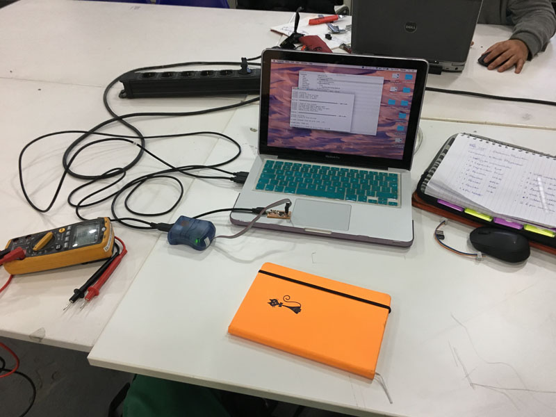
The Electronics Production assignment this week is to prepare the circuitboard layout files from the refrence fab design, mill our own version using the CNC milling machines, then 'stuff it' by selecting and soldering all components. Then to flash the chip to program it, (intially by using another programmer). We will then be using these programmers throughout the course to program other new boards that we create.
Our lecture and introduction this week really was a beautiful electronics 101. We have learnt about the basic history, evolution and function of Computers, the basis of electronics and digital technology as a whole, and the origins of Micro-Processors and Micro-Controllers. Once again this served up lashings of inspiration, but also many doubts and much uncertainty!! Overwhelmed by the scale and complexity of what is out there and what is possible in the digital world of electronics, binary code, resistors, transistors, circuit boards and programming!...
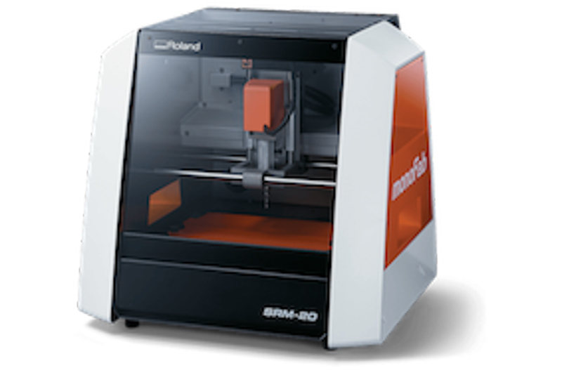
We have also been given an induction and introduction on how to set up and operate our milling machines safely and effectively. We will be using either the Roland MDX-20 or more likely the SRM-20 mills we have available in our lab.
We will also be using 'fabmodules' which is a web based software used to set the tooling, generate cutting paths, and make the g-code file that we will send to the milling machine in order to mill the circuits. The material used for the circuit boards is generally small rectangular sections of copper backed laminated fibre-glass board. It is 1.6mm thick. This thickness will be used to define the depth settings for each path cut and the step of the z axis in fabmodules. Exploring and becoming familiar with the processes of how to mill Printed Circuit boards will be highly valuable in weeks to come.
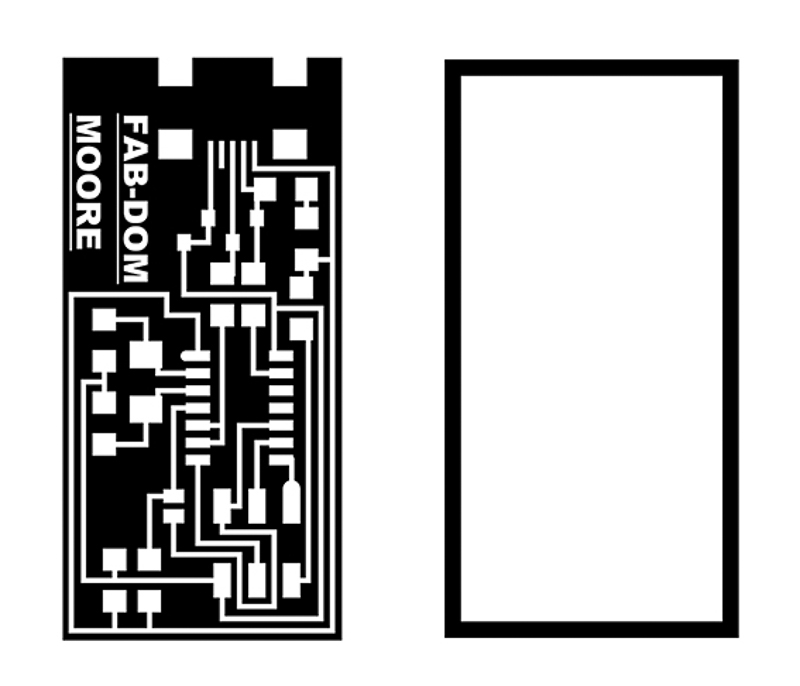
The design files and board layout for the Fab_ISP circuit programmer board this week are provided online as a reference. There are also many archived fab versions from previous students from which to find useful tutorials infromation and advice. Like the majority of us I followed Niel's template pretty rigidly to make my first board, trying to minimise room for error and to end up with a working board to use.
 the reference design
It is easily possible to modify the layout of the components and traces and customise them if we so desired either directly within the circuit design software we are using such as Eagle, or as a post process modifying the .png image file using Photoshop or Gimp or other such software. For now I chose to run with a fairly standard fab-ISP design, mainly due to time limitations. I did do some reading into other commercially available programmer designs also finding interesting information about other fab alterations such as adding an led, or making an interesting shape board outline. Our programmers use a microcontroller themselves the Atmel AT-Tiny 44 and as these require initial bootloading of a flash program we would be needing a factory programmer to provide this initial programming link and make our programmer work. For this purpose we were using a commercial AVRISP (MKII).
I customised my ISP board design a little with my name or initials using gimp, primarily in order to identify my board. Later I might explore some more funky shapes and patterns for some more sexy looking furture boards!
With the image files of our circuit prepared and ready the next task was to set up for milling our board. Primarily we will be using Roland SRM20 milling machines although we also have an MDX20 that has a different attachment with accurate 3D piezo touch probe-scanning capability. These are fairly high precision desk-top units, capable of engraving cutting and shaping fine 3D detail in various flat material.
To prepare our files for output to the Roland Mill we must first adjust and define settings for tooling type, relevant sizes dimensional values, tollerances and origins and then generate the cutting paths and machine g-code for our design. For this purpose we will use Fabmodules. - HTML5 'Fabmodules' which is a browser based software designed and created by MIT's bits and atoms and our head fablab professor, and creative guru - Niel Gershenfeld. This tool provides us with a 'GUI', - a graphic user interface, for converting design files in 2D and 3D into machine commands or g-code. Fabmodules can output to many of the cnc machines in the fab environment, such as the vinyl cutter, epilog or trotec laser and shopbot in addition to the precision Roland SRM 20 mills that we will be using here...I have documented the following process for using this tool which is fairly easy and intuitive.
We will be interfacing the Roland mill directly using the machines own control software 'V-Panel' and then sending the G-code we created in fabmodules from within this interface.
The traces is the first milling operation which removes the thin copper surface layer and leaves behind the remaining circuit paths and pads of our design. For this process a 1/64" (0.39mm) diameter milling bit is used to achieve the fine detail cuts between traces.
Then a a border cut or through-cut is made for the outline using a 1/32" (0.794mm) mill bit. A thicker bit for making the deeper passes cutting through the material for the outside border cut or for holes.
Each of these different processes or cutting operations needs to be set up for properly from start to finish to avoid having any issues. We should have our g-code files prepared saved and ready to send one after the other to mill, allowing for a tool change between. This is very important as at this point we need to maintain our X-Y origin points on the machine for the job being cut, whilst changing the bits, from the traces to border cut for example. The 'z' axis can ammended and reset after changing and adjusting before the secondary cutting operation is sent to cut.
If when you get to the machine the previous user hasn't left it quite as they should! a bit of a clean out and brush down is often needed first, removing any excess dust build up. Pay particular attention to the top surface of the work-bed, or cutting-plate, which may need a rub down with some alcohol and a cloth to remove any sticky tape residue and to ensure a flat even surface before we start. The whole working plate can be removed if required, to aid with cleaning fitting a new and should be tightened securely down by the four thumbscrews in the machine. The blank copper boards are fixed down to the work-bed very effectively using double sided tape in the correct orientation and alignent to match that of our output file.
Check everything is switched on and you are ready. Begin by selecting the correct mill bit for the operation (usually 1/64 traces first). We then open the V-panel Roland Control software which should provide direct manual control to the motion of each axis of the machine. You can set the speed of this movement in increments from slow - x1, 10, 100 or continuous - fast. Give it a try!
Roughly position the X and Y to the front left corner or the 0,0 starting point above where you will cut your board, bring down the z axis so that you have access to easily fit the mill bit into the chuck without it touching the surface, use the allen key to securely tighten the bit into the chuck. Then fine tune the X and Y axis of the spindle and set the 0,0 origin points.
On a slow speed carefully move the Z axis down until the tip is just above the surface, then go back inside the machine loosen the chuck and gently bring down the mill bit to touch the surface of the material and re-tighten, now set point as the Z axis 0, origin. You may find that you benefit from doing this Z check, or a second Z check in the middle of the work area in case of any high spots, and to ensure a better cut accross the surface.
Then back off on the Z axis manually just a little, and finally you're ready to output our rml files to be milled through the V-Panel Software by pressing 'cut'. If you notice something going wrong at any point there is a 'pause' button; where the spindle and machine continues to spin but cutting movement is paused and job is on hold, or the pushing the 'cancel' button ends the current operation and stops the machine.
After seeing a few colleagues fail making their first cuts either due to having unclean, uneven or poorly attached surfaces on the work bed area. Or, by moving either the head or the work during or between cuts, thereby loosing their point of origin. Not setting up bit properly for the 'z' axis, not having it positioned at the the right height in the chuck or tightened properly can also lead to imperfect or incomplete cuts. Proper care and attention and checking is needed to minimise the result of messing up circuit boards that you will have to re-do, or worse breaking the mill bits, that can be pretty costly to replace, or even potential damage or excess wear on the machine. Therefore, I was cautious and mindful to get mine right. In the end I was lucky that my board cut cleanly on the first go.
Milling the Fab-ISP board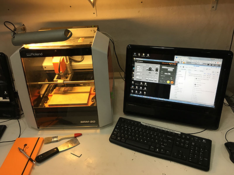
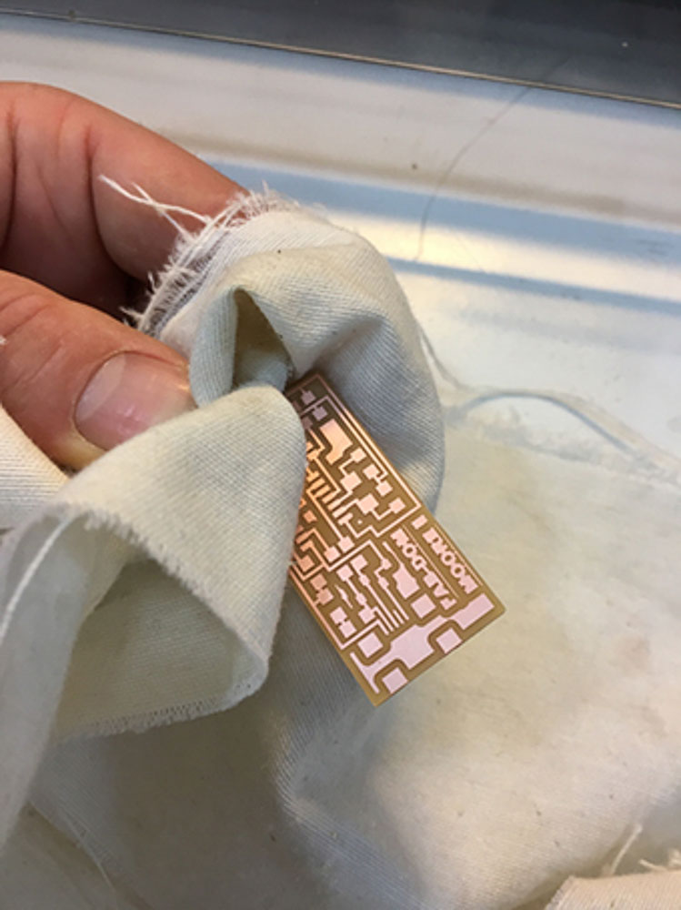 My fab ISP freshly milled!
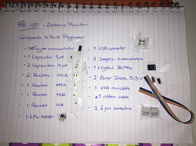
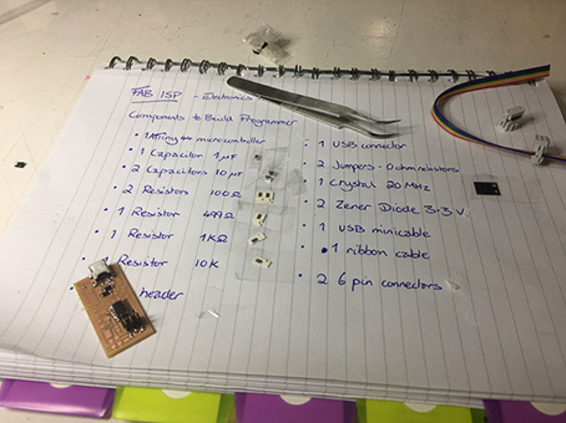
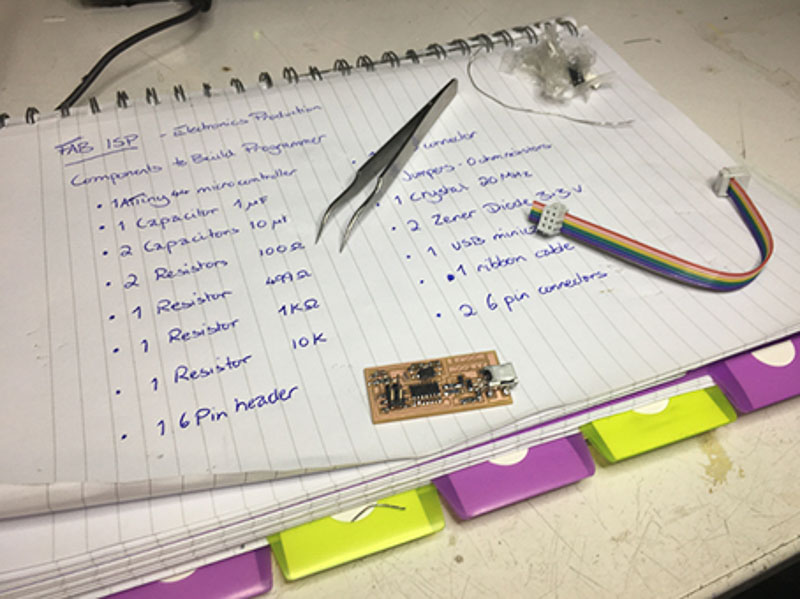
The next task is to select our components; which I labelled and taped into a page in my note-book. And now to begin soldering of the SMT - surface mount components onto our boards. This process of filling the board with it's correct components is known as 'stuffing'. I found that after a bit of practice the soldering was not too difficult and with some patience and attention it was easy to make good connections and get it to flow nicely. Less is more I found, after first seating the component in the correct position capilliary action can be used to tack in position then flow to make a good 'Shiny' joint. Bigger blobs, or flecks of molten solder can get across tracks and other pads and be pretty difficult to remove after the fact. I have had a little prior experience working in electronic diagnostics and with basic electronic projects in my youth, and I found it a surprisingly cathartic experience, I just hoped my board would work properly afterwards!
The final task for this assignment is testing and programming the board. This was quite a complex task, again all completely new to me, so I found extra attention and focus was definitely needed. It was good learning new techniques and processes that I will come to use again. I really hope to develop my understanding of circuitry and programming further in future projects...
Firstly we needed to install the correct software for our operating system, download the USB drivers and Fab ISP firmware, to enable us to first recognise our boards and allow our chips to function when we connect via USB. Then to edit and boot the Makefile, necessary for initiating the first boot instructions to pre-program the new chip. Then we set the fuses, program the board with a set of instructions to become a programmer itself. All with the help of another commercial ISP programmer, which is connected to our computer at the same time as our board. The link between the programmer and our new circuit board is via the 6pin ISP header. For our purposes we used a factory USB AVRISP XPII programmer. Finally I did the smoke test removing the programmer and plugged it in to see the board is identified and verified all working properly. Before lastly opening the junctions by removing the two jumper resistors to unequivocably make our board a programmer!!
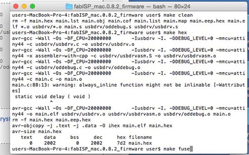
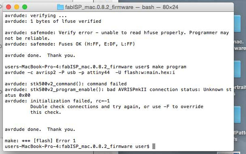

This last stage took me a while as although there was a green light the program initially gave me an error to check my connections, which I did at great length, tidying and reflowing the pins at the USB connection header. Then by changing the two diodes after recommendation from a colleague that this was his solution. It sadly wasn't mine! Although, I did get the module to program it seemed, but it wasnt then being properly recognised at the USB port on my mac or on another computer.
Finally at a very late stage in the day, after I had re-seated and soldered all of the connection points on my board I was still getting connection error message. I then noticed that my resistors were not quite the same colour as other people's boards and reference pictures online confirmed this. I found that these were indeed not the required 1K ohms needed, and I must have inavertedly selected the wrong ones. So after swapping these out at the end of the day, I was most happy to get the programmer accepted, recognised and working. This just shows how meticulous you must be preparing and selecting the right components at the start, especially with such small and often unlabeled components.