This week we study 3D Printing and Scanning technologies in order to identify some advantages and limitations of each of these processes. With practical training and hands on use of the 3D printers and tooling we will gain better technical knowledge and understanding of the processes involved. The first objective is to learn about the design rules for the different 3D printers available. The printers that we are lucky to have up and running and currently ready to use in our Barcelona lab include:
1x Prusa i3
3x Reprap
1x Ultimaker 2
These 3D printers essentially work by feeding and heating a thermosoftening plastic through a small nozzle in a guided manner, they are known as fixed filament or fused deposition - 'FDM' printers. The molten plastic builds up in thin layers or slices to form the 3D object as it solidifies on the print bed. PLA is the most common 3D printing medium due to its low cost and excellent thermal working properties. Other more durable, or specialist 3D printable plasitics include; ABS, polycarbonate, polypropylene, PETG, Nylon, Acetal, PMMA, FPE and even carbon fibre, metal infused polymers or clay.
filament types -3D printing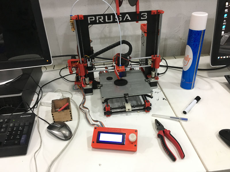 original Prusa i3
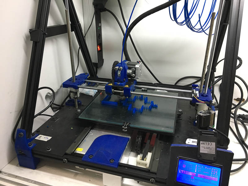 Reprap I
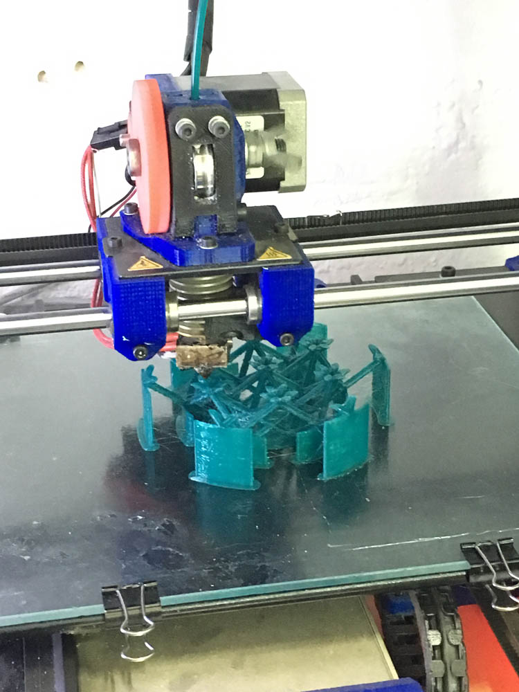 ReprapII
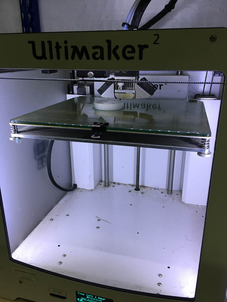 Ultimaker II
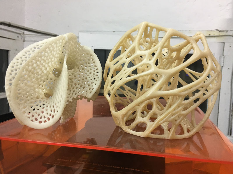
Another type of 3D printer we have available is from Formlab; a desktop version of a 3D laser 'SLA' - stereolithographgy printer, aptly named - Form 1. This differs from the above 'Fused Filament' types, in that it points a high precision laser through a tray of heated molten resin, this causes a thin layer to solidify at the desired points. The 3D part is drawn out of the resin and revealed before your eyes.
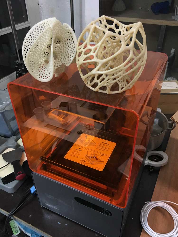
Finally we also have a powder based printer, which is an 'SLS' or selective laser sintering type, that looks very interesting. Although it is more expensive to use, and sadly decomissioned and currently out of action needing complete re-conditioning. The benefits of these latter types of printer is not only their high accuracy and fine detail prints, but the inherrent ability of using the material within the build area surrounding the part as it's support, negating the need to build these structures in with slicing programs, as with the filament types. But the more restrictive and exacting resins and powder packs these two types of printers require easily become a costly consumable. Additionally, the set up time and preparing and cleaning process can be a lot more complicated. Also these printed parts often require some secondary process, or a degree of post processing such as washing in solvent baths to reveal their optimum properties or UV light and heat treatment. However, they both look like they would be really nice to use, it's a shame they are out of action.
SLA and SLS - What are the differences?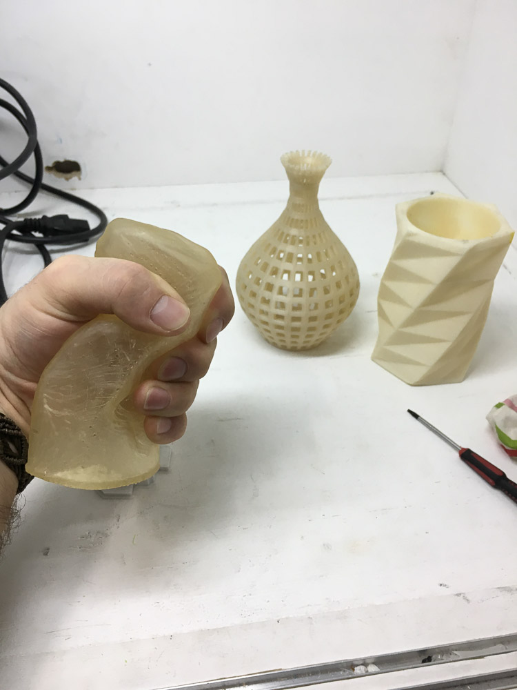
Additionally within this assignment we should try out some of the known 3D-scanning methods and techniques. Allowing us to produce 3D mesh models from real objects. These can then be used to make potential 3d prints and further designs. Finally we need to design and print our own small 3D object, one that could not be made by traditional subtractive methods. This is how I got on...
Firstly, I really enjoyed using the Kinect motion sensing device, this unit was originally designed for Xbox 360 providing in-game motion sensing hardware. The stereo lenses in the unit detects I.R. - infra-red depth, and RGB colour information, with an adjustable range of 1.2-3.5m. Reverse engineering of the code powering this hardware has enabled it to become a cost-effective option for people who want to use it as a 3D scanner; by converting the output to real-time video. Connecting with Skanect software on the computer, it then becomes relatively easy to get a medium detail poly mesh models imported quite quickly to a computer.
I found the proprietary power connector and the bulkiness of this system a little annoying, as when rotating around your chosen subject the cable would be tethered to both power and USB and needed to be flipped out the way and obstructed you making a clean flowing scan. This could well be avoided when scanning smaller stationary objects by using some kind of turntable to rotate the object and having the camera fixed. Some colleagues seemed to manage this quite effectively using wheeled office chairs and a seated subject. On a side note, it did take me ages to install both the software and the drivers to get it working properly on my macbook, but I did learn more computer management skills using terminal and learning about both Macports and then transferring to Homebrew for package and install managers.
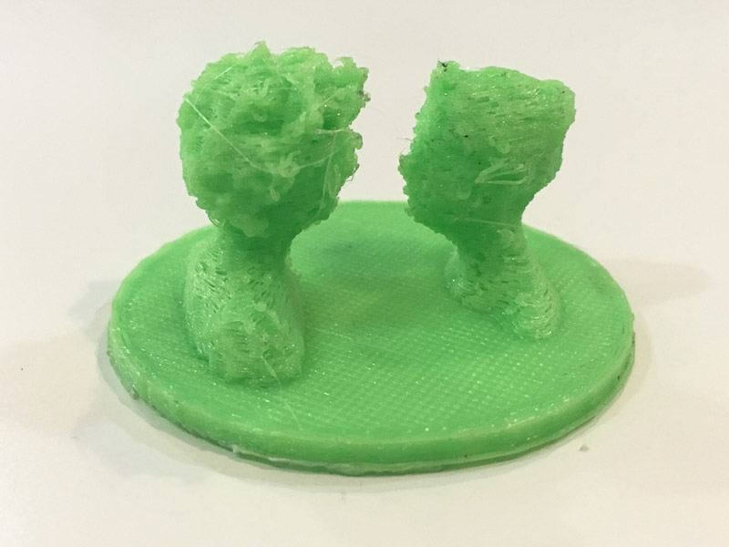
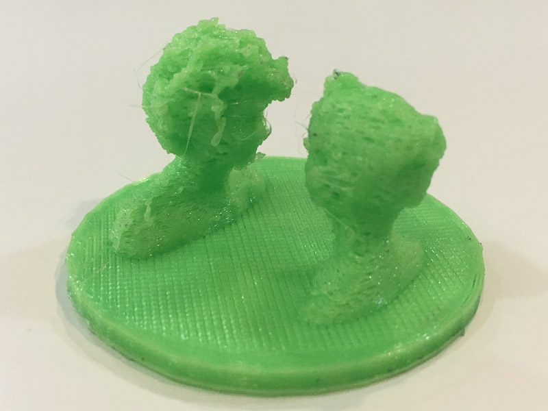
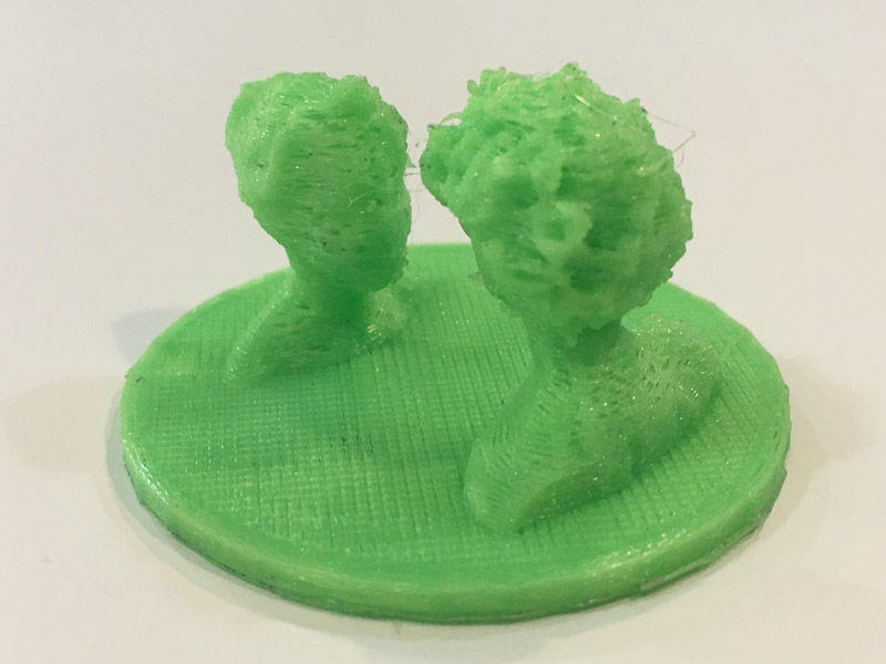
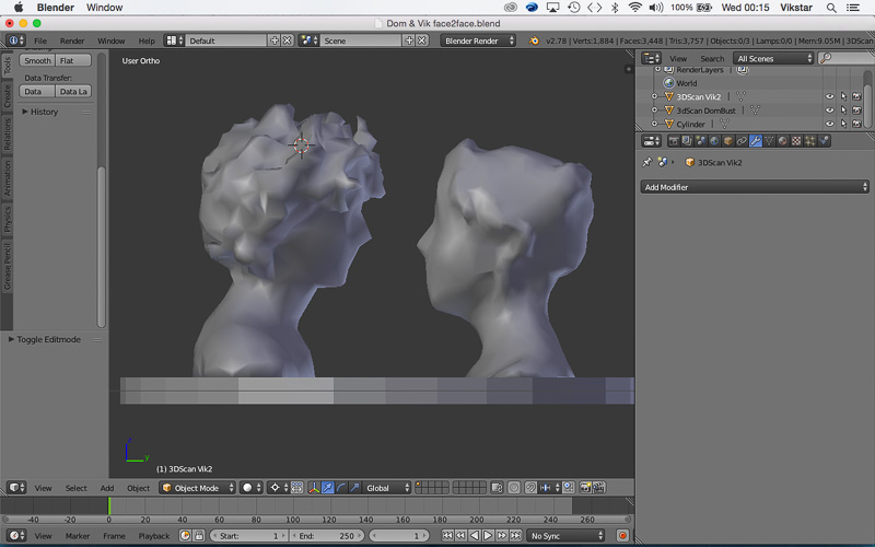
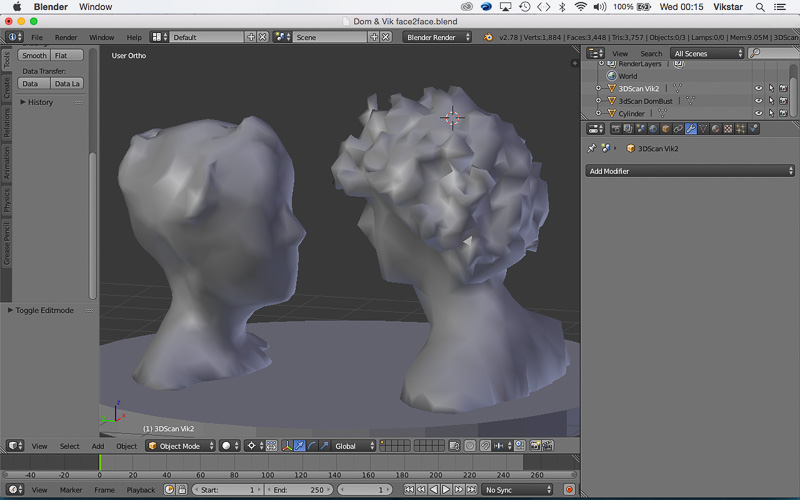
With some patience and the help of a colleague initially we scanned my own bust, and his. And the following day I was also able to get some nice results scanning my wonderful girlfriend who came to join me as my model!
I have seen that there is also a nice portable 'structure sensor' input device available, that connects directly with a tablet, or even an i-phone version, offered by Skanect. If you buy this as a bundle along with the full version of their software It would provide compact, neat and portable solution for making 3D scans which would be great. However, the price they are asking is a bit much for me right now. Although having the full software would allow you to obtain far more detailed and accurate models, considering with the free version you are limited to only 5000 poly faces when saving your scan files. Other versions such as 'i-sense' or 'Asus Xtion' may also be worth a look into, If the price were right I would be very tempted to purchase such a tool.
Overall Kinect offers a reasonably quick, effective and low-cost method of scanning live objects to make a 3d model. It's still probably one of the best and easiest methods available, certainly in relation to more expensive and complex laser scanners or 3D digitizers, tomography x-rays, radiography, photometry and other such devices... However, I am really very interested in doing further research to discover more about Point clouds and triangulation software. Experimenting with different light arrays, and structured light. Or in generating a mesh by making a video, in a high contrast setting, showing the different gradient light stages with a 'milk-scan'. You pour white milk into a receptical containing the object to be scanned to create a high contrast setting, and as it gradually covers the form a 3D image can then be built in layers.
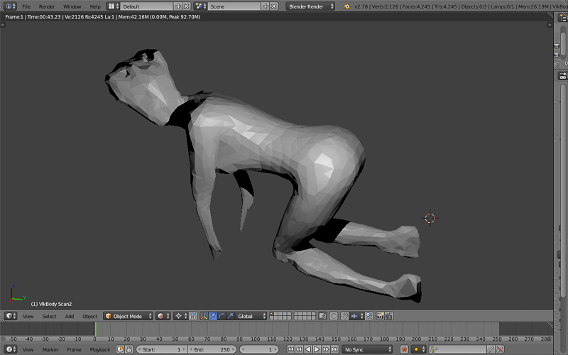
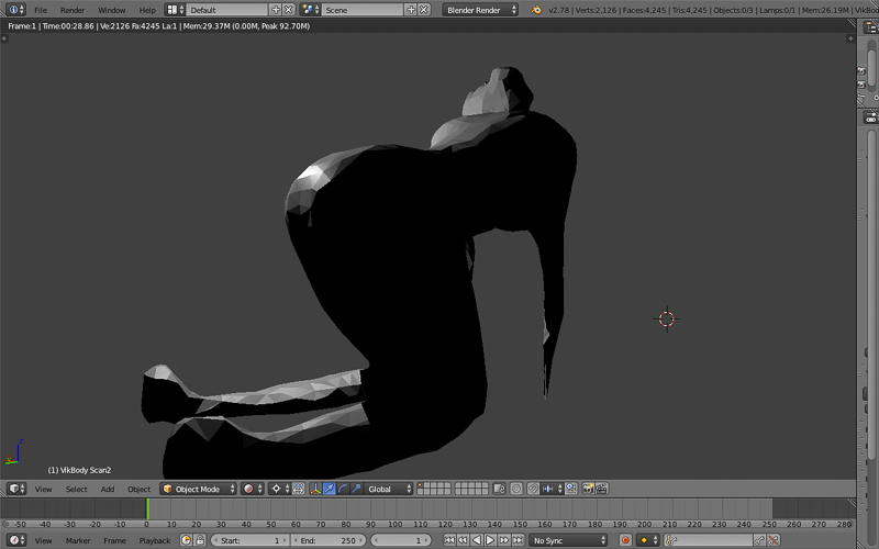
After scanning in a 3D model further cleaning and blending operations to consolidate and refine the surfaces boundaries and edges is then required. You can tweak and play with the .stl mesh within your favourite 3d software to get an all important air tight solid form for 3D print, and tailor surface and edge detail, or edit the features and form entirely. We had another tutorial by Viktor Barberan, to begin taking a closer look at Blender, to demonstrate some of its capabilities and the interesting tool sets within... This is particularly useful software when it comes to sculpting, repairing, smoothing and restructuring or normalising points and surfaces within our meshes. Another complimentary software I have heard of is Meshlab that I also intend to try out at some point. I took this opportunity to really start getting to know this software and its use. Now I feel a lot more confident and familiar with some of the tools, controls and commands and features. I managed to get some nice results from my 3D scans I did of both myself and my Gilfriend head profiles. I really hope I have time to now get a print soon. As the printers were very busy, I started to focus on other ideas I had to develop a 3D model and make something more intricate and potentially useful for my project.
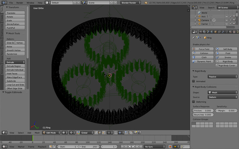
During this time I have been researching Gears and ratios relating to my main project ideas with the kinetic toy or interactive sculpture or the solar tracker. I was focusing on the Spirograph toy or making some kind of drawing robot, as I have seen robotic maker or lego versions on youtube. I wanted to work on gear mechanisms for their practical mechanical applications in many designs areas and when incorporating motors. And also to practice some mathematical construction techniques in the 3D modelling software we have been using. Then also if time permits I want to have play with physics simulation options, testing accuracy of my model and the curve profile of cog teeth and mesh characteristics.
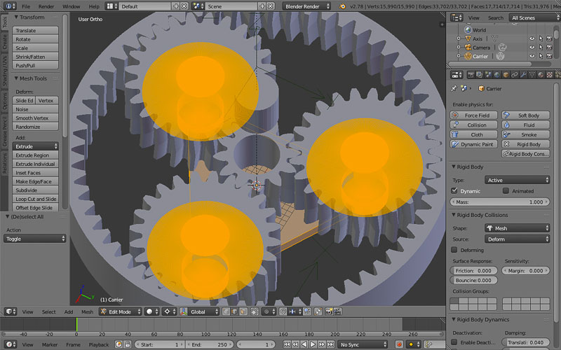
I followed these tutorials online provided by a company called OTVINTA,
They offer some really useful 3d print and modelling services for enthusiasts. They have prototype design files of geared designs in various types, with acompanying tutorials to help you create the 3D files. And most notably some powerful and very useful mathematical calculators and generators; giving you editable parameters and ratios for all kinds of gears, such as:
I was impressed, and this was not only an interesting challenge to help with my progress and understanding of 3D computer modeling of week two's module, but the process was also really good inspiration and instigated further learning and research into geometry in general. Mathematical principles, history of Spacial awareness and measurement. Platonic solids, forming meshes from Polygons, trianlges or quads. and the basic construction and definitions of objects and 3D form, from points or vertices, edges and faces. At this point I was mostly trying to familiarise using Blender software, but also I am switching between SolidWorks and Rhino and I hope to pursue Grasshopper further and aim to get to grips with the parametric modeling functions in the future.
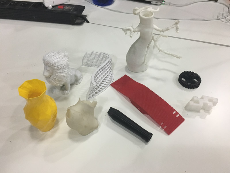
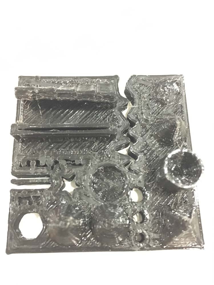
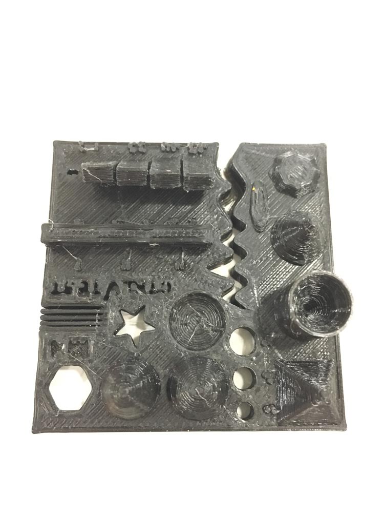
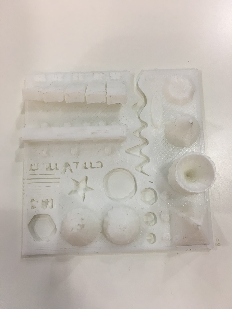
Course instructors worked with us by helping explain the design rules for the printers. Informing how to best set up the printers themselves and in preparing our 3D files and mesh models ready to send. As a group we made some 3D prints using test part files that are available online through thingiverse. These test print parts are designed to be used to push these high resolution 3D printers beyond the machine resolution. In order to test and observe their capabilities and limitations. The machine accuracy and tollerance, and the effects of changing set-up variables can then be taken into consideration within the design process. Noteably; features such as having excessively thin wall thicknesses, sharp obtuse points, internal cavities, and overhangs are all potential 'fail' points in 3D printing. However, tight tolerances, scaling of intricate features, holes, embossed type-face, slots and live hinge parts can all be achieved easily by making certain tweaks and alterations with the set up. The following link shows more detail what we observed and learnt about during the process.
The following tests were made in our lab colaboratively using and comparing the RepRap and Prusa printers, adjusting the nozzzle size from 0.3 - 0.4 and 0.6mm. Please see the link for more detailed assessment and comparison of parameters and considerations when using the 3D printers.
3D Printing design rules, setup and tollerance tests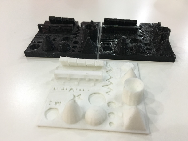
There are many CAD programs available which cater to 3D printing which offer simple and basic functions to streamline 3D print generation and output. These inlcude SketchUp, FreeCad, TinkerCad, Autodesk 123D Make (which I beleive is now re-make), Meshlab or Meshmixer and also Fusion360, to name just a few, I downloaded a couple of these which I shall be experimenting in using. Though for now I am just as happy using Blender, Rhino and SolidWorks as my fully featured 3DCAD programs.
A slicer software such as Cura or Slic3r generates the 'G-code', the language understood by the printers to complete the job. allows us to set the print parameters from profiles we have set up with and extended set of pre production tools for visualisation of the job. We are able to analyze our .stl files, position models, orient, scale or edit them and adjust the print settings prior to making a final 3D print. Ideally you would find a good print profile to start from, one matched for the printer you are intending on using. Preferably, your set up file and printer choice can be confirmed by speaking to someone who has used that specific machine previously or has real world understanding of the settings needed to make consistent good prints. If not, online guidelines and notes for set-up, installation and use of each printer are also available.
Luckily for us a colleague Tomás shared his profiles that he created for each of the printers in our lab, he has previously done an internship here, and is highly knowledgeable about 3D printing. We also have a new intern Miguel to help with our technical querries and issues when printing our files. For each printer you first need to choose a specific filament and material to use and colour, depending on what is availiable. By far the most common and recommended seems to be printing in a plastic called PLA - PolyLacticAcid, which is a low toxicity biodegradeable thermoplastic and perhaps the most environmentally friendly and suitable choice compared to other petrochemical plastics. Although several other types of material are possible even metal particles in suspension or food grade products can be used to make prints. Here is a good article for more information on filament and material choice.
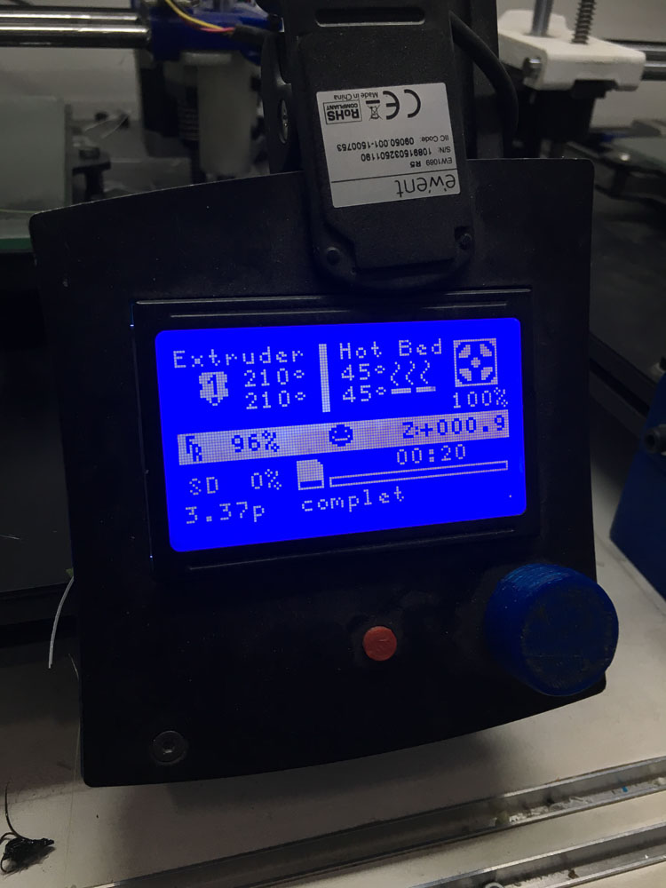
Ensure that machines are calibrated and tuned properly before you start, checking that surfaces are clean flat and level and print head alignment looks right, check that nothing is loose motors and belts are tensioned correctly and everything is in good working order. We then need to adjust parameters for extrusion feed rate, speeds layer height, nozzle type and size. As well as print temperature of the extruder head for even flow, and also heating of the bed or build plate for good adhesion of the all important first layers. There are several extra integral printing changes such as the percentage and type of in-fill to have between internal walls. If you need to build support structures allowing successful printing of protrundences, openings, cavities and overhanging features, you can set the amount and type of structure used. There are some nice ways of examining further for defects or problems one might face, using the slicer tool you scan through sections or slices of the model replicating how it will build, providing visualisation tools such as solid, xray and layers of how the file will be printed.
exploring the capabilities and limitations and some of the differences between the printers we have available at our lab has been a difficult task mainly due to the demand of people trying to print, and the limitation of time that would be needed to look at change and tweak the settings and compare the different printers with different design features settigns and materials. However I do feel like I now have sufficient knowledge to understand the basic principles and criteria for making 3D scans and prints.
Things like time, cost, material choice and its suitability or availability, resolution and detail, supports and fills, internal structure, wall and edge thickness, clearances and orientation were all important considerations to be made. Also everyone wanted to print their designs so the demand for print-time became quite heavy in our lab.
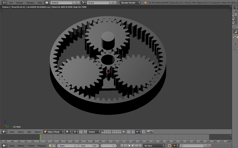
So far from my designs I have only managed to successfully print a simple gear from my planetary gear model, and not the entire working assembly as I would have liked. I am also adjusting my conceptual and geometric models of parts that can't be made through a subtractive means, and hope to print something else more meaningful and beautiful very shortly


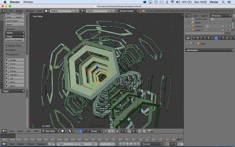
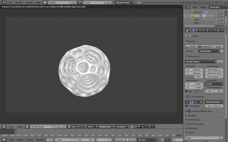
I was really trying to achieve a complex shape, one that could not easily be made by reductive means. I had tried to print a model of a dodecahedron nested within itself six times to reflect the six edges of it's hexagonal faces. Then I added a connecting conical bridge fusing the dodecahedrons together into a a base that would act as my single support when printing. Unfortunately this print was a failiure and had to be turned off when they shut the lab, the layers aparently were printing over each other incorrectly. And now it must wait for another day, it was a fairly detailed model and would take some hours to print in the scale it needed to be at to get the full resolution right on the interior holes and spaces. I hope I might get a chance to try again.


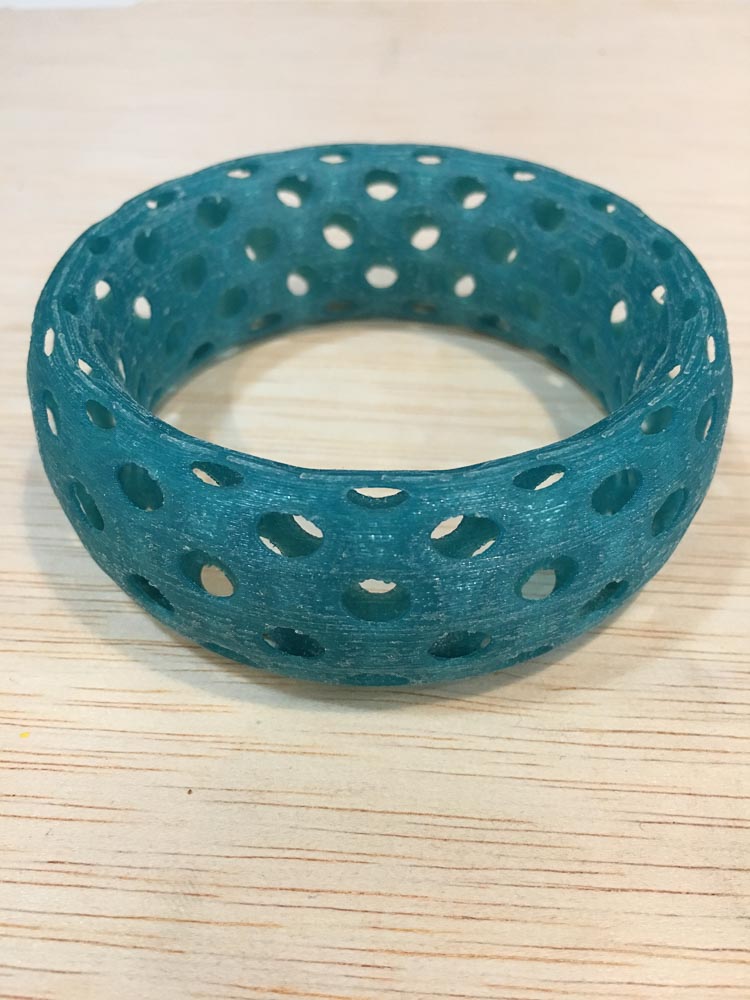
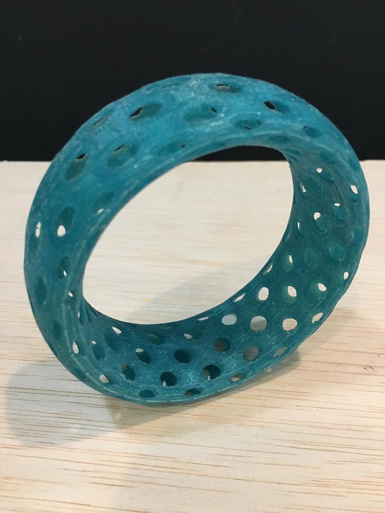
Some time later I was also playing around with torus shapes and wire frame like holes in blender. I modelled an ear-plug piece to wear as body jewelery, but at the scale I had done it at it would apparently have been too fine detailed to print the holes around the edges and the wall thicknesses would have been too thin to support the fine detail. And so I was able to print this shape in a larger scale as a potential bracelet from a similar mesh I had also made in blender.
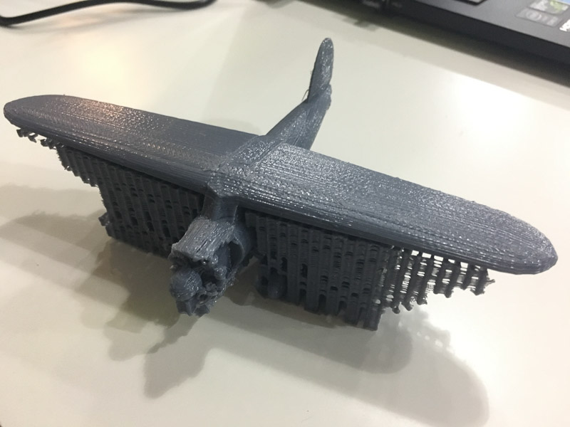
This following video link shows the print process and a friends model we 3D scanned together then he eddited to create a wire frame bust. Printed using the RepRap printer:
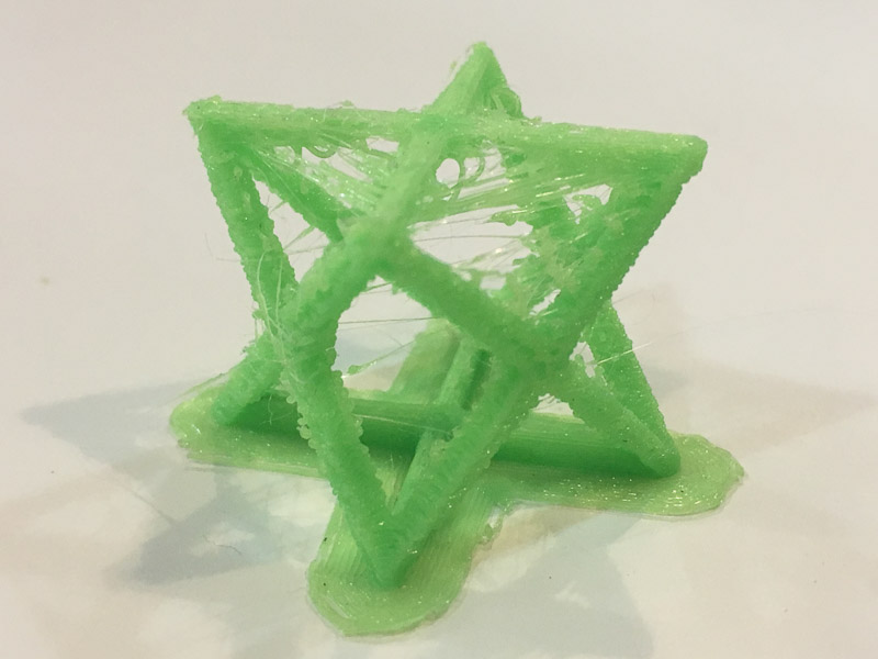
Eventually when demand for the printers had died down a bit, I was able to make some successful prints from 3D files I had editted of mine and my girlfriends scanned busts, and a more simple geometric shape in the form of a Merkaba test piece...
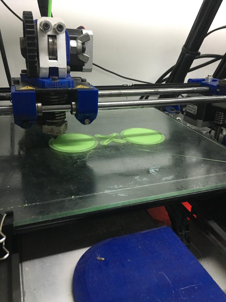
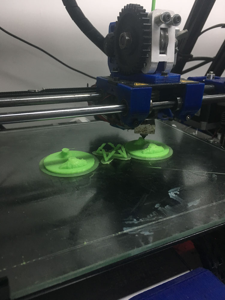
These are the results: