This weeks task is to add an output to a circuit board we have designed.
We have already had practice now in milling circuit boards, and electronics production with circuit board layout and design. We have also studied our component choices and some background information on microcontrollers and embedded programming. Particularly with our old friend the ATtiny.
We have just had an introduction lecture in using 'python' and I feel I am starting to become more familiar with basic programming operations and commands. Now comes the oportunity to show what we can achieve with our electronic designing skills and to add an output and program it to function in some way...
It is possible to integrate a large range of different outputs onto a circuit board and then control their output from our micro controller with the relevant programming. And then, later possibly in week 12, we could also define control over this movement or activation further by using signals from an input sensor or device.
Our options include:
Optical Output Devices: such as a simple leds, or lights or complex arrays of them, to an LCD matrix screen, or even full video output.
Audio Output Devices: like a buzzer or a speaker, an amplifier or sub base!
Moving Actuator Outputs: the largest group being motors but also including other forms of actuator such as solenoids, piezo electric materials, or Mems and SMA - shape memory alloys and micro - muscles.
The possibilities are endless!...
As we have been working on our Solar tracker together toward the group machine project it seems most sensible to pursue my studies further about motors. In particular we have been using the Nema 17 stepper motors that were easily available and on-hand in our lab. And generally are very popular in the maker environment.
Referencing some of links above there one can find some very useful Information about motors. All motors work on the principle that force is experienced in the direction perpendicular to magnetic field and the current, when field and current are made to interact with each other this creates the drive to spin the rotor shaft. I will take an oportunity to briefly discuss what I have learnt about different types and classes of motor:
AC motors come in synchronous and asynchronous forms. For instance an induction motor is asynchronous and comprises of a wire-wound stator and a rotor shaft. Power is connected to the wires and AC current flows which induces an electromagnetic field in the coiled wire with a strong enough field provides the alternating force to drive the shaft. Synchronous AC are constant-speed motors which operate in scychronism with AC line frequency, commonly used when constant precise speed is required.
Many industrial applications use the DC motor because of the ease in controlling direction and speed with a wide range of loads. A DC motor can be either brushed or brushless in its design. Generally they are cheap with quick start and stop, acceleration and high starting torque and a linear speed/torque curve. The direction of current implies the direction of rotation and the speed can be changed by altering the supply voltage, or alternatively you can use pulse-width-modulation (PWM) switching to regulate speed, without needing to regulate and control power as much. Gear reductions are almost allways used to reduce speed and increase torque.
A brushed motor will have a certain configuration of windings in series, shunt or compound design forming electromagnets, or using a permanent magnet to control the polarity of magnetic fields and generate motion in the motor shaft.
A brushless motor is mechanically mush simpler and can alleiviate problems with short life-span and wear that can occur with a brushed motor. They are controlled by hall effect sensors that can detect the position of the rotor to adjust the flow of current in the rotor coils and regulate the speed. This design has little maintenance long-life and high efficiency. Have a slightly higher cost due to controller complexity. But they do give speed and positional control and are proven to be rugged and reliable.
A good example of a brushless D.C. motor would be the Nema range of stepper motors that are very popular in the maker community for machines in the lab such as the 3D printers and smaller mills.
A permanent Magnet Stepper Motor can operate with or without feedback with the motion of the rotor broken up into small steps or angles, controlled by pulsed signal commands, can be stopped precisely at a known step point without need for brakes or clutches. Generally they will stay locked in the last position when not ender exessive load conditions. Multiple steppers can be maintained in sychronization from a common control source.
Stepper motors also come in two varieties a uni-polar and bi-polar design. A unipolar design will have two windings per stator phase one for each pole, and polar switching can occur without changing current direction. Hence driving a uni-polar stepper is simpler as one end of each coil is connected and made common, therefore they do not require the more complex H-bridge IC needed for the bipolar designs, However the drawback is that only only half the winding will be energised at one time so the torque and power will be far less. A bipolar stepper motor has one winding per stator phase, with a two phase bipolar stepper motor you will have 4 leads. In a bipolar stepper we don’t have a common lead like in a uni-polar stepper motor. Hence, there is no natural reversal of current through the winding, and the current needs to be reversed. Although they have an easy wiring arrangement their control is inherrently a little more complex. We need an IC that can has an internal H-bridge in order to handle the current change at and the polarity change at the stator poles of the motor. Also the H-bridge can handle the high current draw associated with these types of motor, and accomodate the spikes generated when the coil current changes direction and so they help to protect the micro-controller. There are many common H Bridge IC such as the L293D, Alegro A4982, Pololo A4953, A4988 and DVR8825 drivers and carriers. There are many ways of controlling stepper motors more information can be found in the links above. A fine degree of motion and accuracy can be achieved especially using micro-stepping.
Servo motors are used in a closed-loop system with some form of digital speed controller to amplify and send drive signals controlling speed movement amount and direction, and some form of encoder or resolver to relate the motors position and speed back to the controller. Continous servos are available for some applications, but more commonly they operate by defining the specific angle within the servos range of movement usually 0°-180° PWM control uses the timings of a square wave signal generated within the controller code to output to the servo. Servos are good for fast and accurate positioning and have a very dynamic range of speed and high speed of acceleration. However they generally have less torque and certainly the larger more powerful motors than the common micro R.C. versions can become increasingly more costly.
For this assignment I am working on producing something similar to Niel's example - for the bipolar stepper motor driver circuit board. This then could be used or a later dual edition adapted to power our solar tracker project instead of using commercial shields and motor carriers as the output drivers.
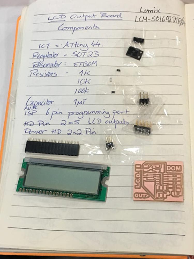
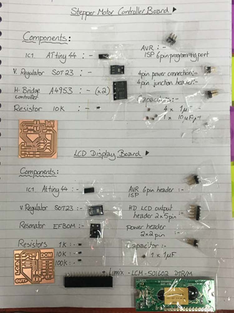
Once I found the correct datasheet to identify the two A4953 H-Bridge motor controller chips, as well as selecting from a vast range voltage regulators components to find the SOT23 that I needed. And by reading through much information about motors and electronics I now had a little better idea of this circuit. These will be the components used...
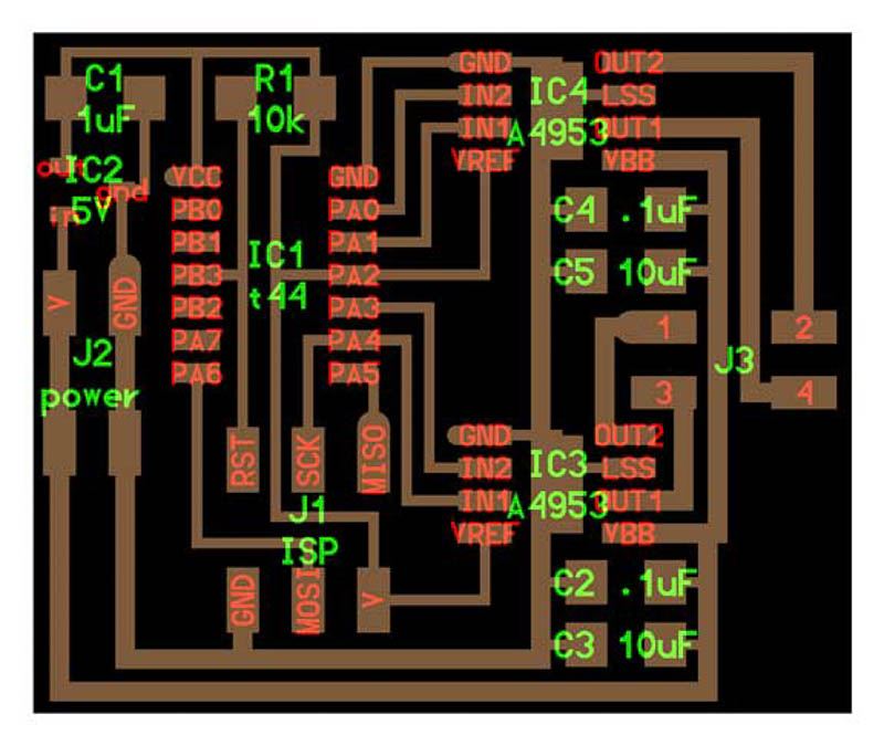
![]()
I used Autodesk's Eagle software to source my components from the fab library, and to design the board-layoyut of my circuit board for milling. I added the correct components and labelled my schematic accordingly.
I encountered some difficulties at first routing the traces, I was finding it wouldn't let me route the last few traces where I wanted them to go; in accordance to the reference circuit design. I must have had some component labelling or rotation issues between my schematic and the board layout. I spent a significant amount of time frustratingly trying to rectify the situation by examining each pin and traces and identify my labeling of Inputs and outputs, trying resolve my conflict. In the end I found it much quicker and easier to re-do my board within a fresh project in Eagle. This time I was more careful to first label key GND and VCC pins giving me the correct orientation of the pins to then get the rotation and position of all components visually arranged in board layout mode, to match that of the reference circuit design I was using, then I proceeded to label the rest of the inputs and outputs in the schematic mode, and finally do the routing back in board mode to finish the circuit. Thanks also to a colleague of mine Trini, who showed me her board layout which helped me enormously with routing and making the following design.
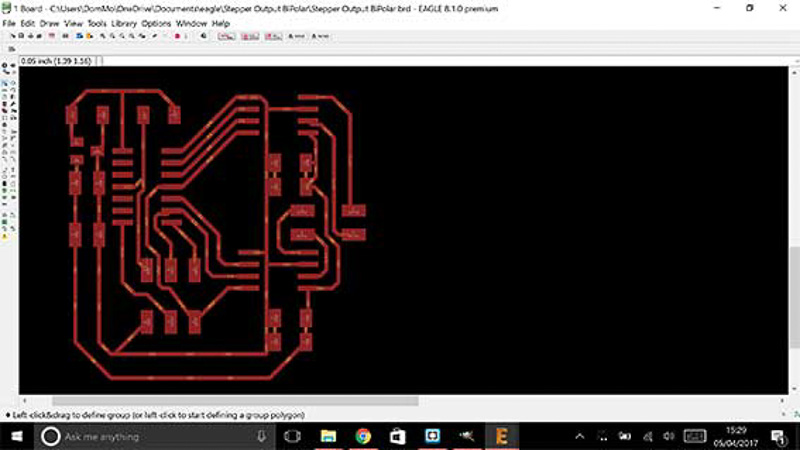
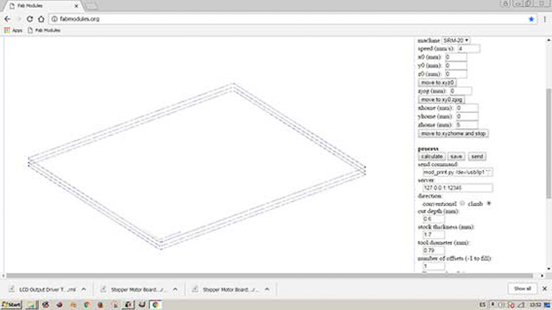
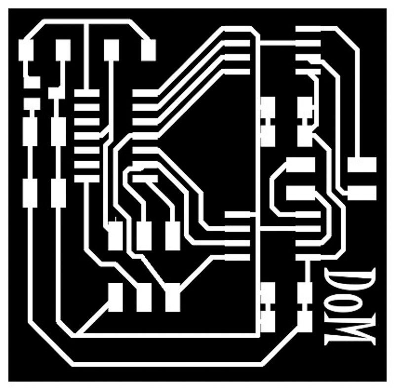 Board layout
 SSRM_20 mill set-up
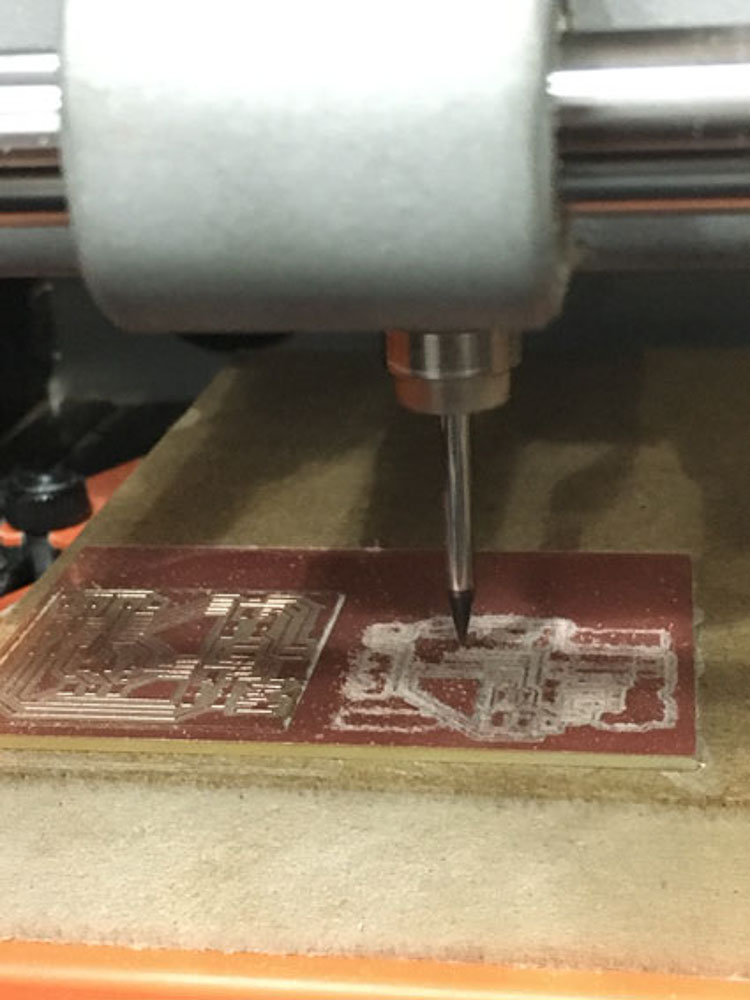
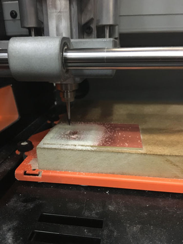 Milling
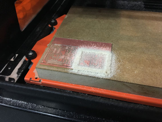
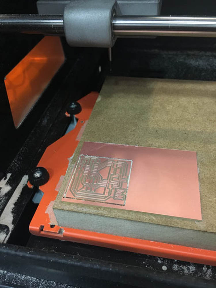 Milled Board
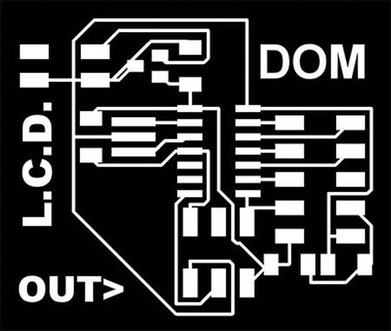
During my technical frustrations with the Motor board schematics, and the ongoing research reading up about technicalities of motors, I have also been looking at the LCD driver board another potential easier option to program an output. I am really interested in understanding a bit about how to build a board and use it to display data recieved from a light sensor or humidity and temperature sensor for example as an input device. This would be a nice, useful output board to learn about and it seemed a simple enough board to produce in terms of it's components. Although I had no idea about programming it yet, it could be fun to make!
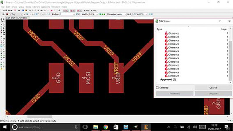
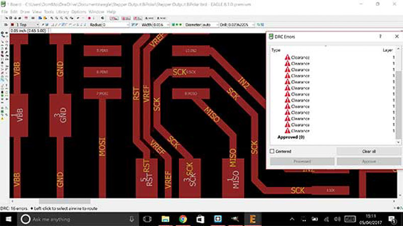
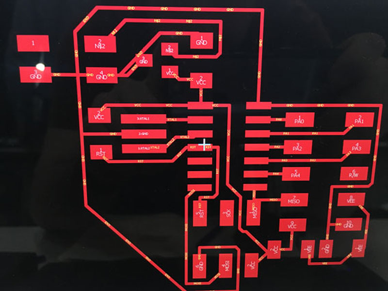
I referenced our instructor Xavi's board from his documentation last year, which was very helpful. I placed the components carefully oriented them and labelled pins correctly, this time autoroute seemed to give an effective output. I checked this with a 'DRC' design rules check, and annoyingly the traces were too close after not first changing the design rules to the 0.16mm clearance we needed to for our standard 1/64" size milling bit. So I moved around some components, lenghened and squeezed apart some traces around the sharp corners. Then set the proper clearances, and did another auto-route to find the successful outcome shown below. This time the process went a lot more smoothly
As I had the time I milled it on the same pcb next to the motor driver board.
Finally I had two boards milled and ready to be stuffed with their components.
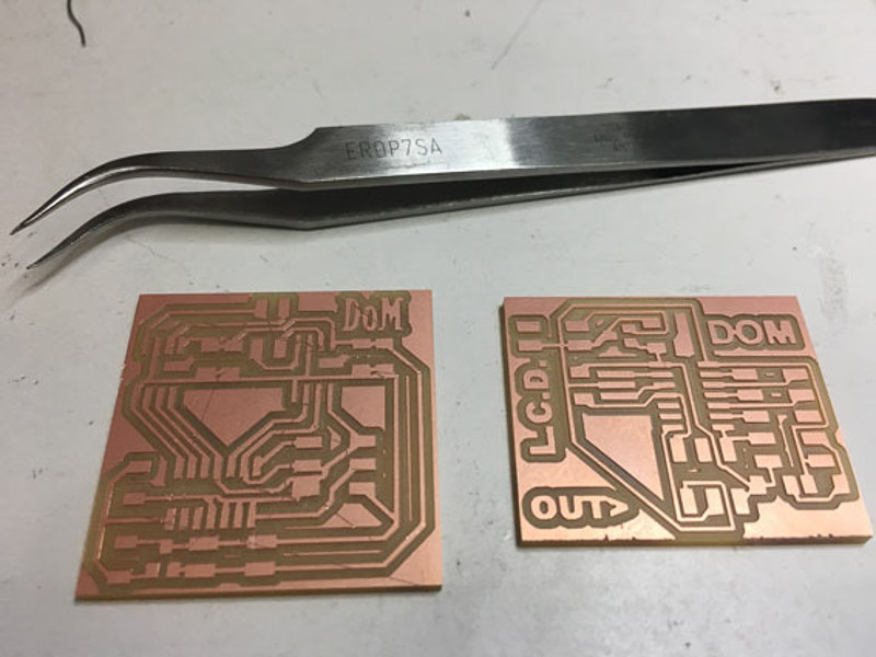
I did the soldering and they turned out like this
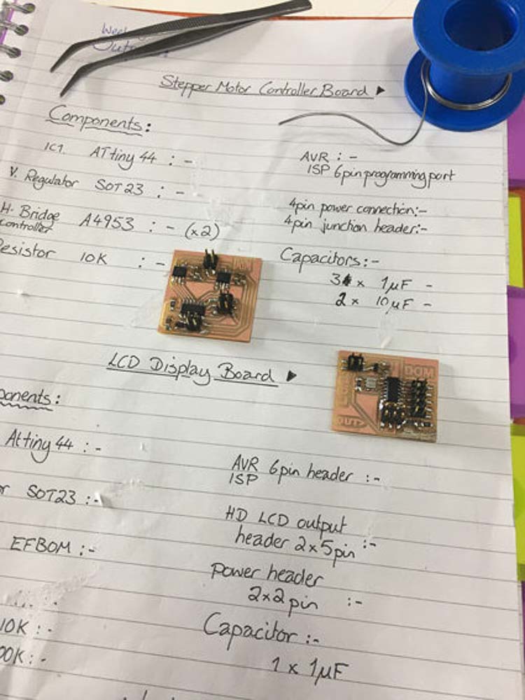
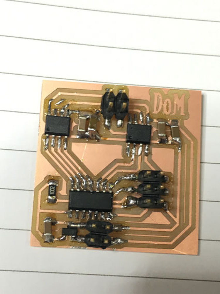 Stepper output board
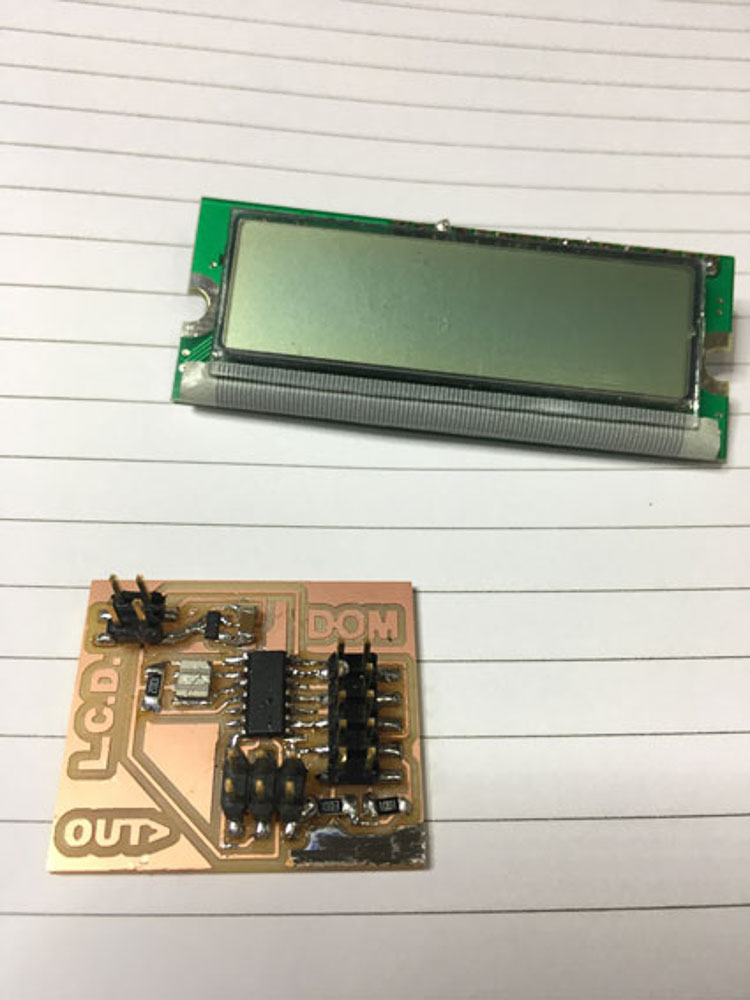 LCD output board
Now was time for testing, unfortunately both boards would not work at first and would not accept a burn bootload, either when using my fabISP programmaer or the factory AVRISP. So I went back to the multimeter and circuit diagrams to try to rectify a potential connection problem error.
Since our ongoing endeavours and early tests with the group project, and my failiure to yet make a successful stepper-motor output board during this week. I have been making steady progress getting to grips with the coding, functions and circuitry for motor control. Currently, I am using an Arduino Uno board, combined with a breadboard and the Pololo drivers with an external 12V power supply necessary to drive the 0.6-1.2A for the twin stepper motors.
Single Nema17 with Pololo DVR8825 and ArduinoI have also been experimenting with servo control at home, as they can be run off 5V USB, or a 9V external power and through the arduino directly; The motors are controlled with their PWM functions, which nicely the arduino IDE has libraries for by inludinging # Servo.h before then define and set up your servo motor(s) within your adruino sketch, we then write straight simple code functions to give positional movement and feedback within a looped time sequence.
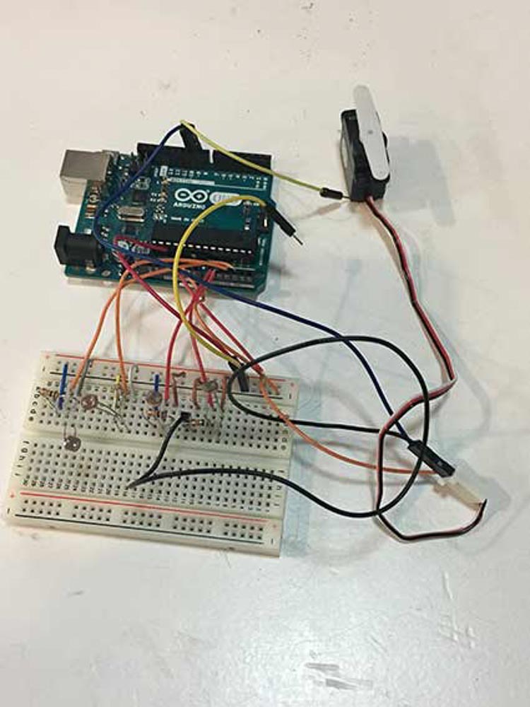
I am also trying to test and evaluating our group project sketch attempting to perfect our code or our sensors in order to move both motors according to the light intensity and angle from 4 LDR sensors and their values. More can be seen in week 9 and week 11 and our Group Machine Solar Tracker Project web site...
I went on to try a firefly sketch using the grasshopper pluggin for Rhino, following a useful tutorial I was successful to gain contol of my motors. Then I encorporated a Joystick to control two mini servos on a miniature pan tilt. The following video links show the various success I have made in programming and controlling different types of motor outputs.