Milling on CNC router
The spotlight in this assignment is being put on Shopbot!
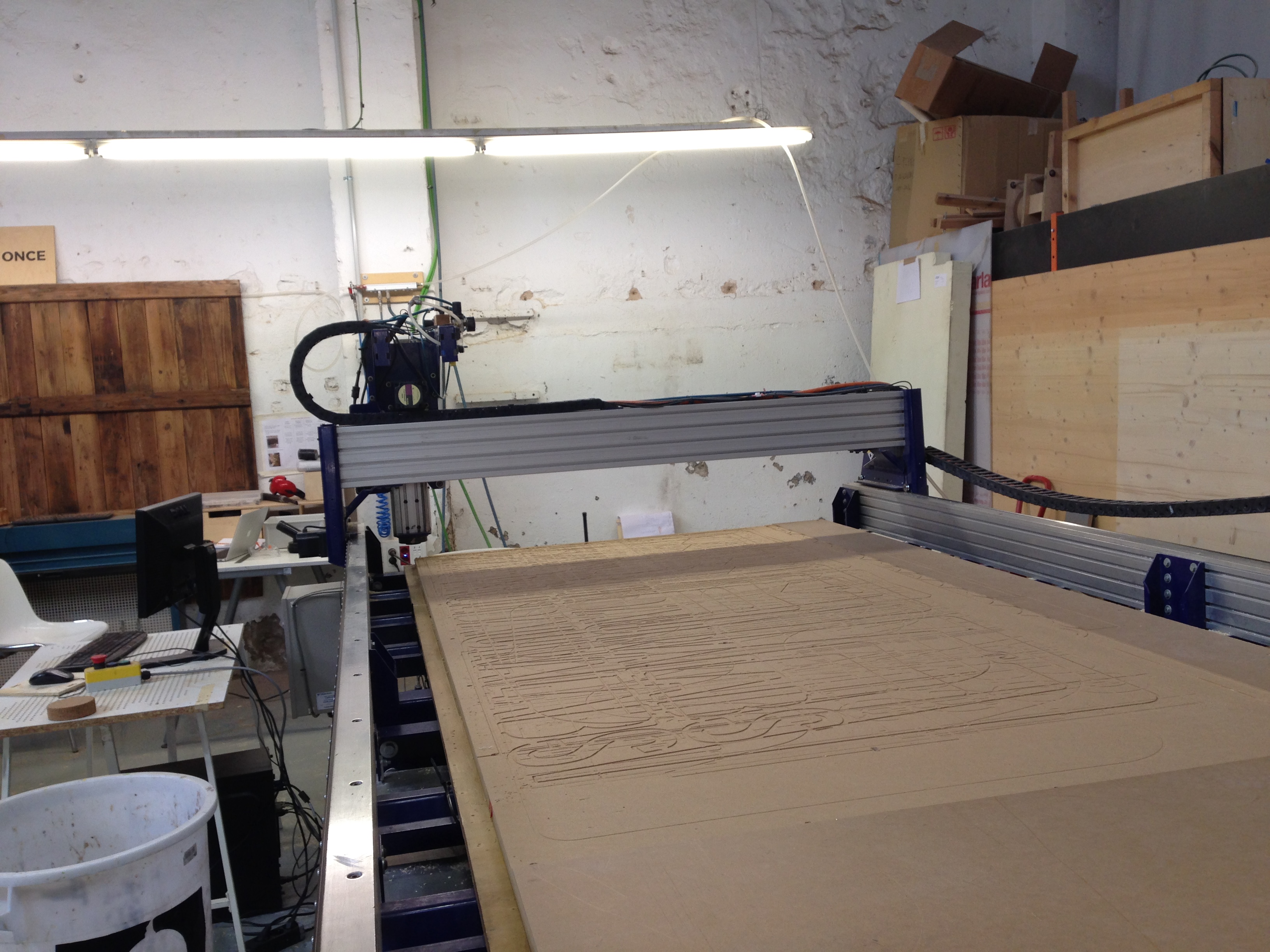
It’s Computerized numerical control (CNC) milling machine, with 3 axis, and interchangeable rotary tool.
Work area is 4270 x 2310 x 1730 mm. You can work with materials such as: Polyurethane foams, cork, wax, wood, MDF, soft materials that can be milled. The file format prepared for the machine should be G-code. One can use it for milling of 3-D models, full scale furniture parts, molds for casting, architectural models etc.
Link fo Shopbot FabLabWiki
Link to datasheet
Link to machine website
Link to the Shopbot control software
I have the following beautiful notes, thanks to Kris who did the group documentation.
RhinoCAM is the preferred software for CAM at Fab Lab BCN. In order to use it, you have to type RhinoCAM2015 in the command line of Rhino and hit ENTER. You can use DXF file format with RhinoCAM.
Make sure that you are in the MILL module.
The strategies that we are going to use this week are the 2 Axis strategies. One might ask why 2 axis for X, Y and Z? It is because Z is not considered as an axis in this case.
Facing or Roughing is used to flatten the top layer of the material.
Pocketing is for creating pockets, or pits in other words, into the material. One can create things like boxes or cups by using this strategy.
Profiling is used to follow a vector line in order to cut something. You can position the tool on one side of the line (similar to tangent contstraint in CAD).
Engraving is similar to profiling, but insdead of movig the tool on one side of the line, the center of the tool follows the line.
V-Carving relates to tools that have a V shape. It is useful for cuts that have to be in an angle. It is also useful for engraving text. Nice for creating decorative cuts that employ depth and shadow-play.
Hole Pocketing is used to create holes. It is similar to Pocketing, but does not leave material on the bottom. It cuts as deep as the defined material thickness.
Hole Profiling creates holes, but instead of using the pocketing / engraving approach, it cuts the pieces out by using their outlines. It is important to use tabs for this strategy.
Add tabs to pieces that will be cut out from the material in order to avoid excessive amounts of panic!
Tabs keep the pieces to be removed in place while cutting your material. You would cut the tabs after the milling machine has finished its job. You would use a hammer and a chisel or a handsaw to do the final cuts. If there are no tabs, the piece can get loose, jump off and destroy your lab!
Click on Post to open the Post Processor Options window. ShopBot MTC post processor has to be used for the ShopBot milling machine. Mach3MM post processor has to be used for the Precix machine. Go to Fab Lab BCN Wiki to learn more.
Post File Extension has to be set to .sbp.
Click on Stock to specify material that we are going to use for milling.
You can import 3D objects from other 3D software, but you have to make sure that the top surface matches the Z axis origin (value 0).
Creating the stock usually involves creating a new Box Stock instance. The origin of the Box Stock should be set the top-left corner of the box representation.
Measure your material before creating the stock instance.
Stock from selection can be used as well. You can define your material by drawing in the 3D view. You can extrude the outline downwards in order to define the material thickness. When you are done, click on Stock and select Stock from selection.
Click on Stock visibility icon to enable a ghost image of your material. You can delete the original object, the stock ghost will be still there.
You should position the bottom-left of the material at the X0, Y0 position of the 3D view.
It is important to mark where you are going to put the screws for attaching the material to the build plate of the milling machine.
The first CNC strategy is going to be for the screw marking. Add single points to mark the places where you want to add screws. If you skip this, you have a higher possibility to break the tool as it hits the screws. You (and the machine) should know where they are.
Holes/Drill can be used to mark the skrew locations. Select the points which define the drilling locations.
Tool selection lets you define parameters for the tool you are using.
The less flutes your tool has, the faster you have to go in terms of RPM.
Search: ShopBot chip load. Use GUHDO chipload calculator https://guhdo.com/chipload-calculator (scroll down to the bottom of the page).
Clearance is the tool traveling distance above the material when rapidly changing location. It is important to set it if you use attachments that stand out above the material.
We are going to do most tasks with a 6mm tool. First steps are the following.
- Put the material on the build plane of the machine.
- Set the origin of the milling machine.
- Use the screw marking strategy.
- Dogbones are additional interior corner cuts for connecting parts. Dogbones one has to define herself for interior corners of connecting parts. Since the tool of a milling machine is circular, it is not possible to create sharp interior corners otherwise.
The fast way of creating dogbones is to define points on a separate layer in RhinoCAM and create a drilling strategy from them.
Hit the Play button to preview the simulation of the created strategies.
To create a strategy, you have to select one or more paths in your design and then choose a strategy template from the Program menu. A window will open and you will have to define additional parameters.
Cut Parameters define how the tool should move along the line and in what direction it should spin. In Global Prameters you can specify such parameters as Tolerance which specifies what is the maximum distance of the interpolated line from the actual vector toolpath. Region refers to the path that we are selecting in RhinoCAM’s design.
Cut Levels you hace to specify At Top for the Location of Cut Geometry. Add 1mm more for the Total Cut Depth in order to make sure that the tool cuts through.
You can do most things with Pocketing, Engraving and Profiling.
It is good practice to create your paths using layers. Create one for marking, engraving, pocketing and profiling. That let’s you to select all paths that you want to relate to a strategy at once. The more parts you have, the more time and effort you can save with this.
The range of the Spindle Speed is from 6,000 to 14,000 RPM (rounds per minute). Feed Rate unit is millimeters per minute. 3200 mm/min is a good start for a 6mm tool with 12,000 RPM.
There are two cutting modes. Sometimes we might want to go slow at the end of a cutting strategy. Rough Depth refers to the depth we want to cut fast or rough. Finish Depth refets to the depth that we might want to cut slowly in order to reach highter cut quality. For each cutting mode we can specify depth cuts. For a 14mm rough cut we might specify 7mm depth cut step which will result in 2 cuts. For 2mm finish cut we might choose 1mm depth cut step and end up with 2 finishing cuts for the last 2mm of the material.
Rough Depth Cut should be less or equal to the diameter of the tool. For the Finish Depth Cut it should be generally less than the diameter of the tool.
Do not forget to add tabs to your profiling strategies!
Advanced Cut Parameters is the place where you can find
Tools Machining Options click on Regions in order to define paths that will have custom tabs. Create a new region and use the Manual Bridge Points on selection tool to add custom locations for your tabs. Then in the Control Geometry part of the strategy parameters, select the Select Predefined in order to select the predefined region with manually added tabs.
Select the strategies you want to export, right-click and select Post to generate continous machine code for the selected strategies.
Add a number in front of the strategy file to be able to tell the sequence of the strategies you want to run.
Below is a YouTube video that can help to understand most of the things discussed above.
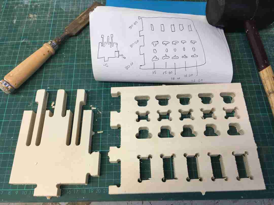
Test cut
As a part of the group assignment we were checking the tolerances in the press fit solution. We were working with plywood 16mm thick.
We were using Nicos design for testing the tolerance. The files were processed in RhinoCam and saved as G-code. Unfortunatelly RhinoCam is really overwhealming for me. I don’t use Rhino for designing thus was a bit hard to follow the CAM process. For working with my piece I’m going to choose Fusion 360 and it’s CAM option!
Together with Santi we set up the parameters for the test cut. The tool that we are going to use is Flat 6mm, 1 flute, and the parameters are the following:
- RPM: 12000
- Plunge: 1000
- Travelling clearance plane: 4000
- Step down: 4mm max
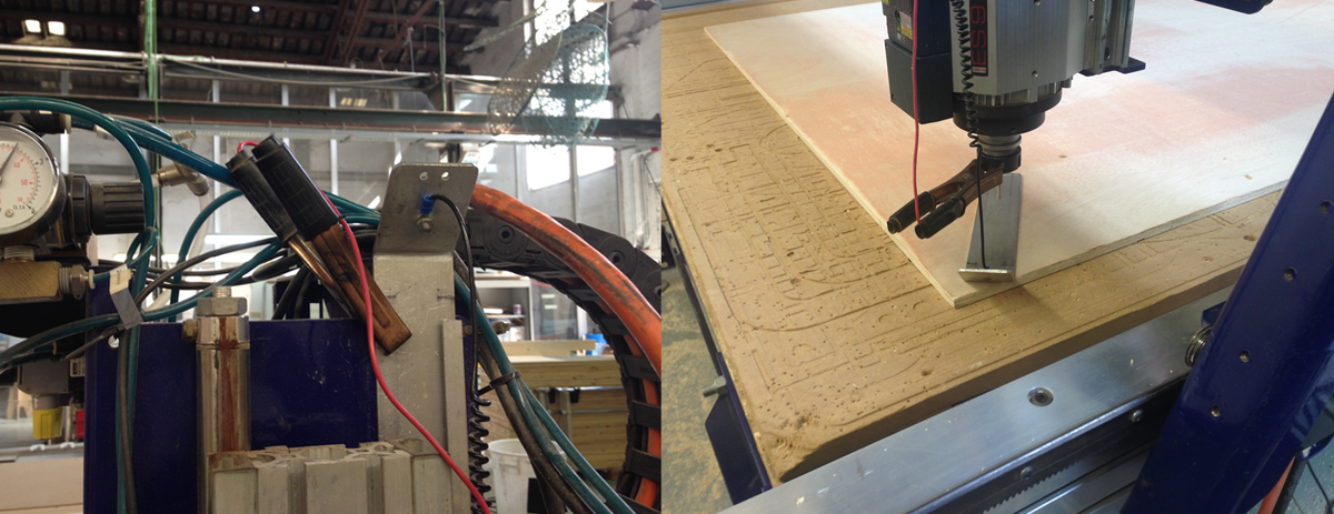
Cutting on ShopBot went nice and we were able to test the press-fit tolerance in reality!
The conclusions was that for getting the most stabile press fit tab-hole match kerf in size 0.2 on each sides would work the best. I’m going to use this experience while designing my piece.
Chipload
Chipload is the size of the chips which are being produced during cutting on the machine.
The goal for calculating the proper chip load is to reduce heat and increase productivity. The chipload shouldn’t be too small (sawdast) since it can cose overheating of the bit. It also shouldn’t be too big since this can cose scraggy surface finishing.
Chipload is dependent on the Bit size you are using and the cutting speed.
During the demo of ShopbotWe we’ve got the information what should be Speed and Feeds values for applying them in CAM. Though is good to know how to calculate them, since probably in the future we are going to work with many different materials.
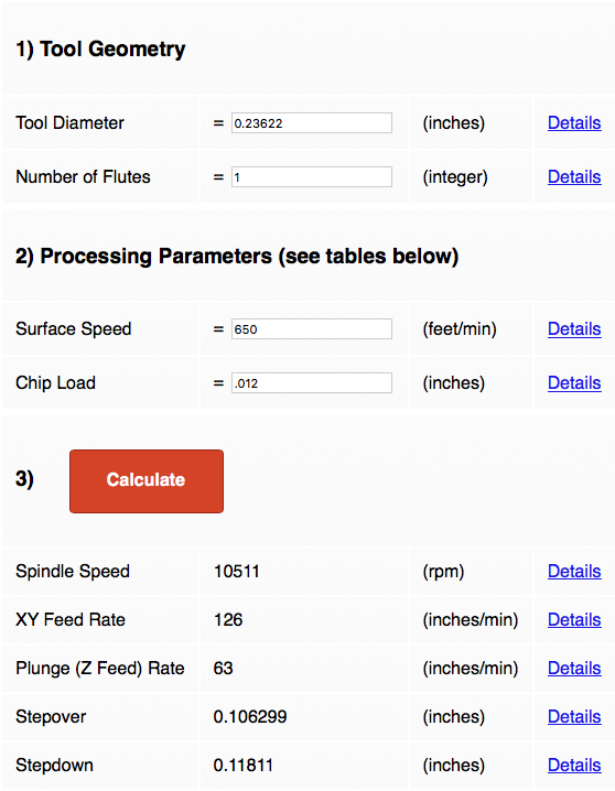
To calculate this values for other materials we can use Fablab Speed and Feeds Calculator.
When you scroll down you see two tables:
- Generic Surface Speed Reference
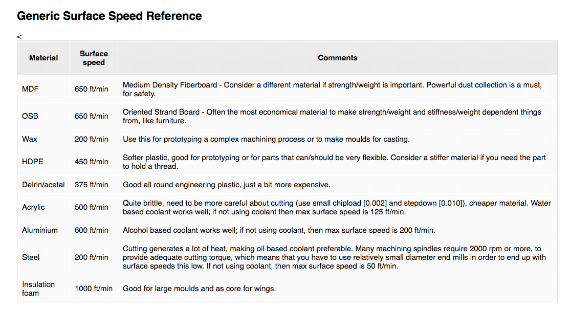
- Chip load
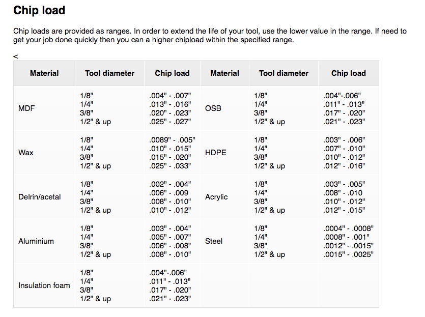
This two values are usually given by the provider of the machines. You can use this information plus information about tool diameter and number of fluts, to calculate feeds and speed.
The formula is as following:
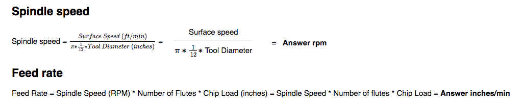
BUT! Instead of doing this complicated mathematics you can use the calculator mentioned above.
After filling in thevalues for 6mm one flute tool, and taking the surfacce speed and chip load for OSB material (there is no plywood but values for OSB should workas well) I’m getting the result which is similar to one given us by the tutor (spindle speed 12000).
Making something big
And here comes reality and a lot of problems…
Designing in Fusion 360
Some inspirations: http://www.sketchchair.cc/
I think Fuson 360 is a great programm to design parametric design. I want my night-shelf (that I’m going to mill) to be parametric, and connected with wood thickness. Fusion also has a CAM option which make sense to use if designing in this programm. From the first look doesn’t seem so overwhelming as RhinoCAM!
To understand better how to approach the design process I was following this tutorial: https://www.youtube.com/watch?v=VZU_Jpyyc5M
My design is going to be similar, though the difference is that is going to be parametric. Becouse of that I’m not going to follow the steps where the pockets for tabs are created by intersecting them. (Of course I’ve done that at the beginning which cost me re-designing nearly everything…)
Also I didn’t used the dogbone plugin and created the dogbones one by one, though aftertalking with other friends I guess itmake sense to use it. Just ifyou have any negative spaces excep dogbones you shouldnt put them everywhere automatically,but select the edges and put them where you want. Adding dogbones has to be done in the design of an object not in a assambly!
Using plug-in:
- main top menu in Fusion: add-ins, choose previously installed “Dogbone”
- new icon appears in menu “create” - dogbone
- in the dialog box choose a body, type in the tool diameter (6mm). One have to choose body not the component.
- other way: select the edges when the dogbone should be done (if one doesn’t want to have them everywhere)
There was also a tipp from professional cnc operator that it’s better (in case if the dogbones are the size of the drill) to mark them as points not to design the circles. Drill can’t make this circle since it’s too less space.
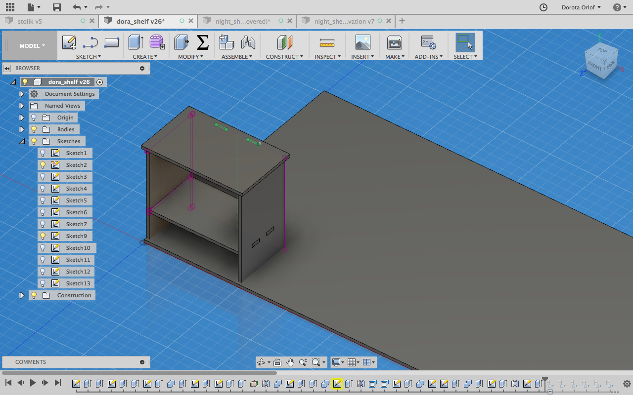
Designing the night cupboard
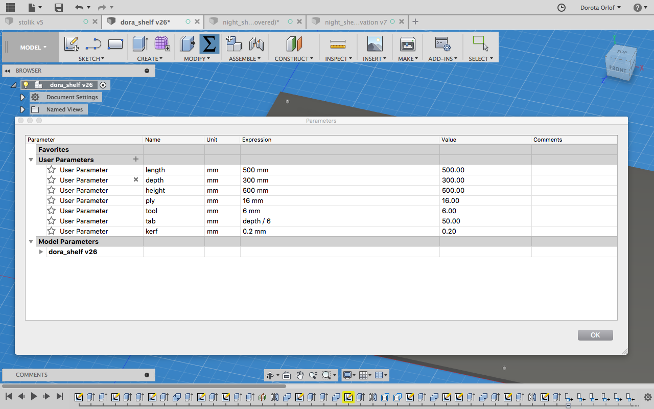
I’m with setting up the parameters like plywood thickness, length, depth etc. I’ma also defining kerf that should works the best: 0.2 mm, each side. We were doing group tests with our machine and this value was giving the best results.
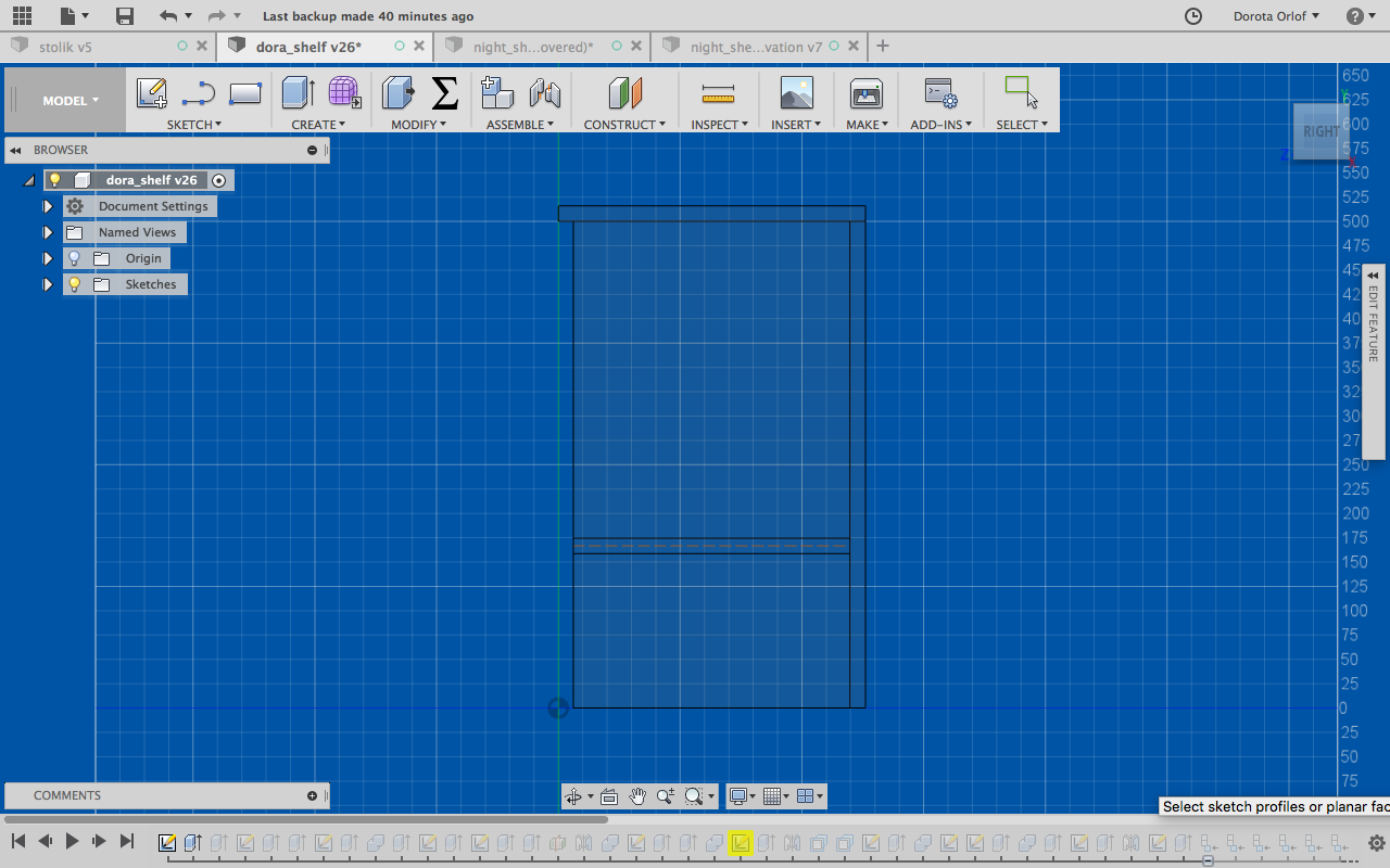
Than I’m drawing the first sketch which gives me the structure att he beginning. It’s the sketch for left wall. I’m basically going the extrude the parts for specific values (set up as parameters).
I’m using a lot mirroring function since my design is pretty symmetric. I’m mirroring the wall, based on previousely made construction plane.
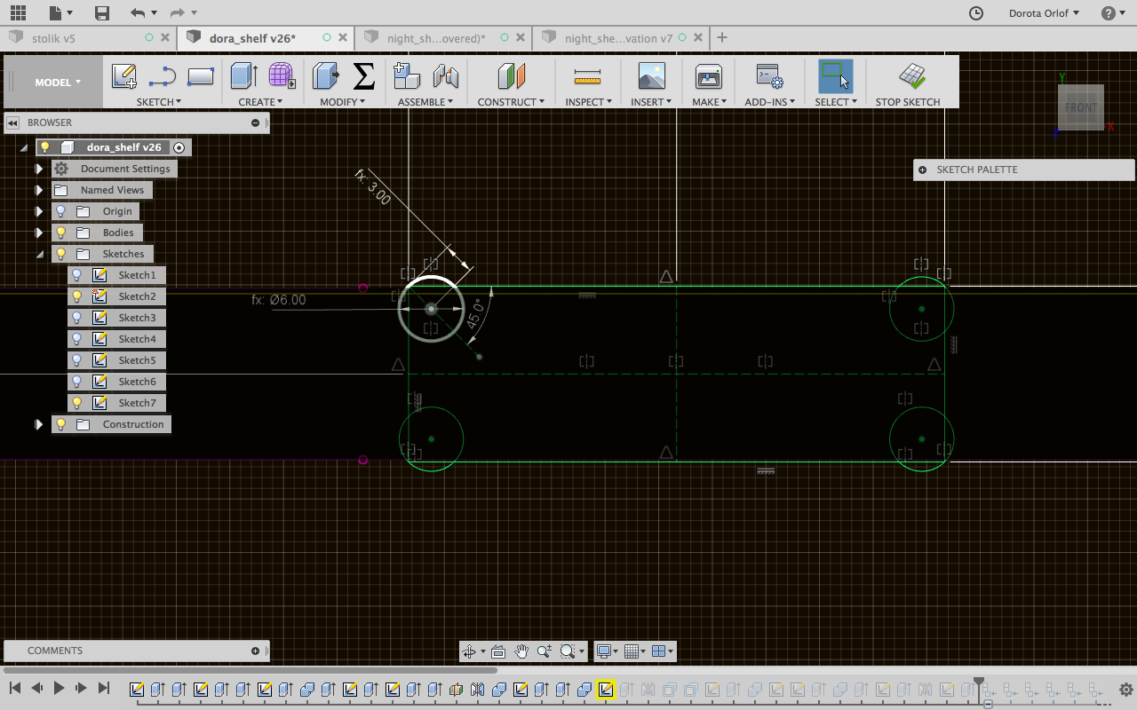
In the sketch mode I’m creating the holes for tabs and dogbones at their corners. Following recommendation of Kris I’ve designedmy dogbones according to thisschematics:
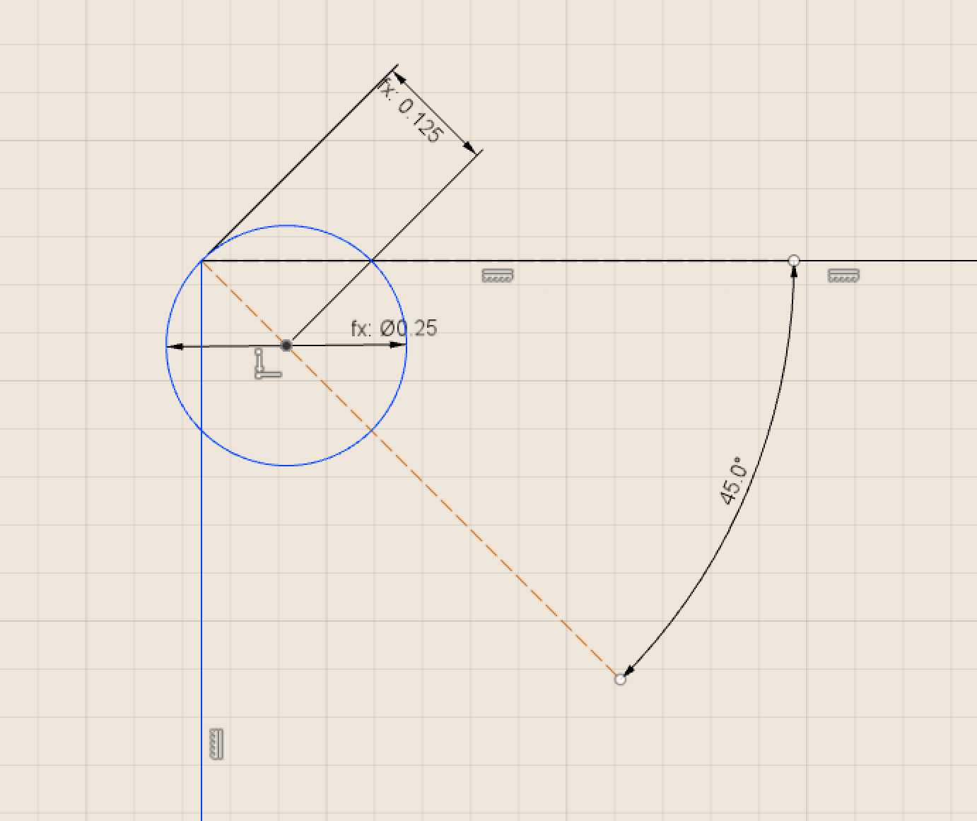
I coping dogbones using ‘mirroring option’.
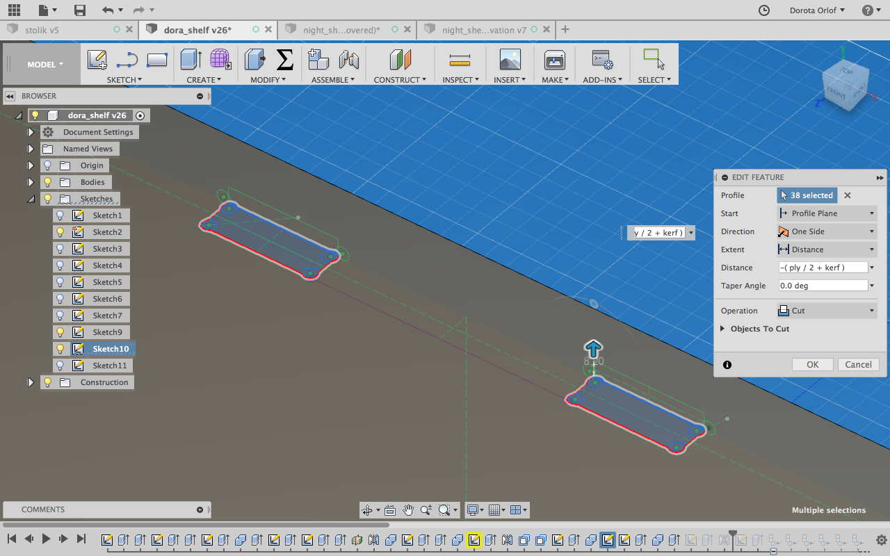
Than I’m extruding them and setting-up the cut operation for extrusion.
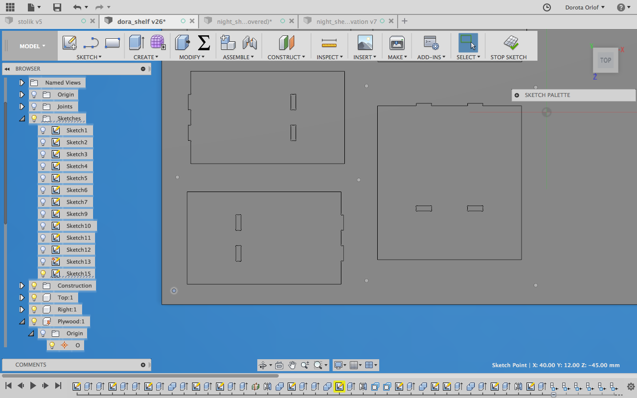
After designing all the walls I have to think about distributing them on the wooden plane that I want to use for cutting. I’m making a new sketch and defining the dimensions of the material. I’m grounding it and making unselectable.
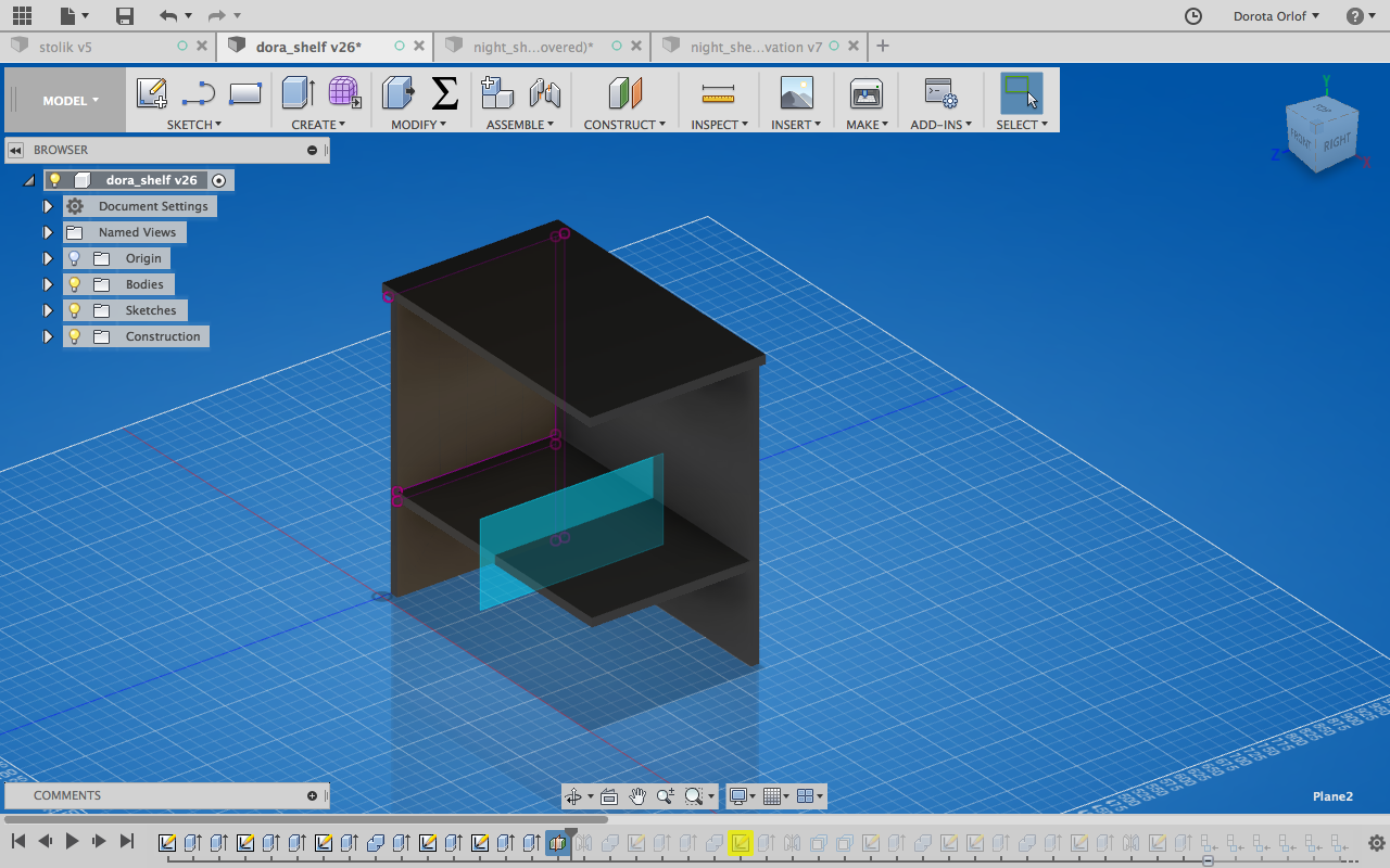
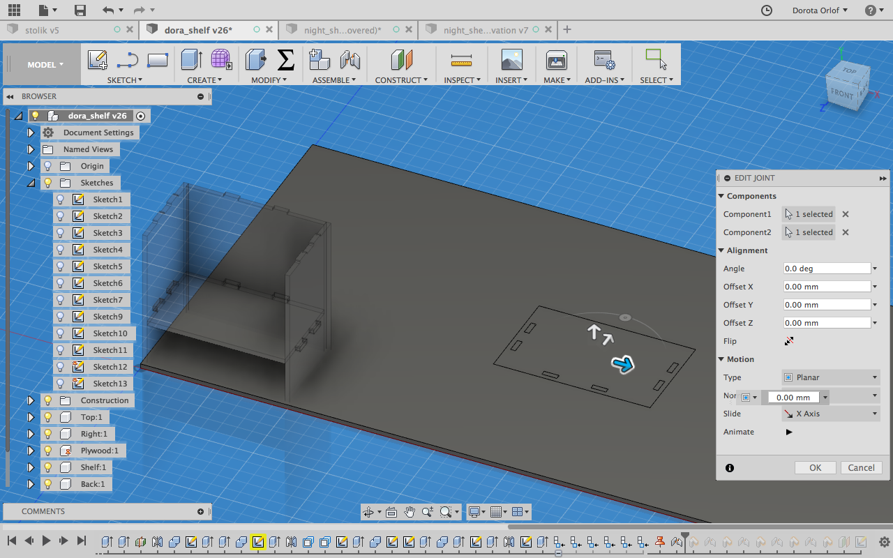
Next thing I’m makeing a component from each body and distribute the components one by one by using Assable > Joint(type:planar) I’m marking an option flip since for joining I was choosing the top surfaces of the elements and plane. So if I want elements to be “inside” the plane (and half-pockets to be visible) I have to flip them.
Here before flipping:
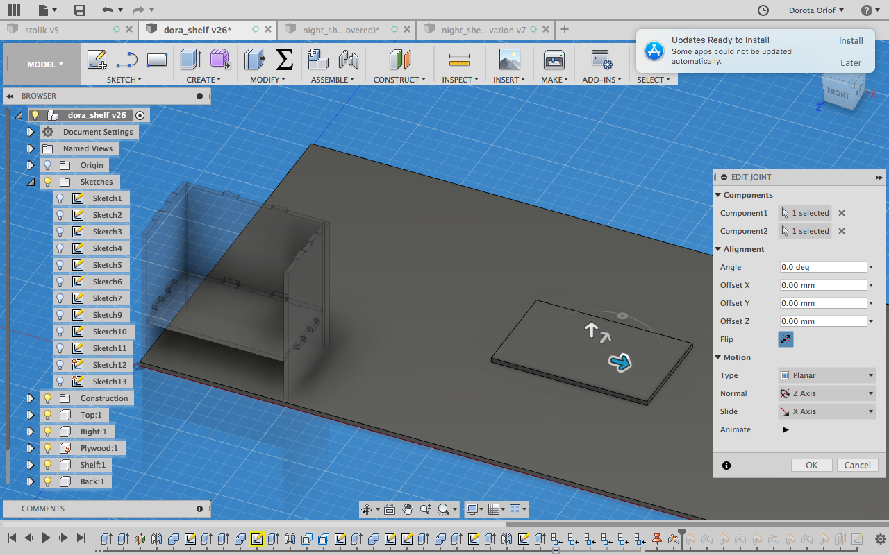
Here flipped:
Now I want to put the points where the holes for screws should be drilled. I’m creating construction plane (offset plane) 4mm underneath the plate sufrace. There I’m going to set my points to get4mm deep holes-marks. To createthis operation you have to make the plane selectable. (When question: capture position)
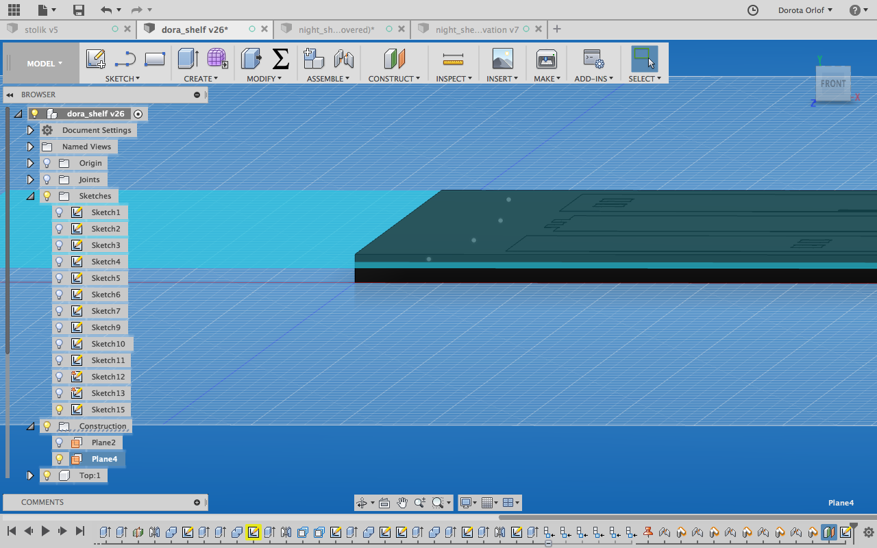
I’m setting the points equally distributed around the pieces which are going to be cut out.
FusionCAM:
Now, when I have all the components distributed on the base component,I can start making the strategies for milling in CAM. Layout is analogic as one in the Model mode. Here I’m describing key points:
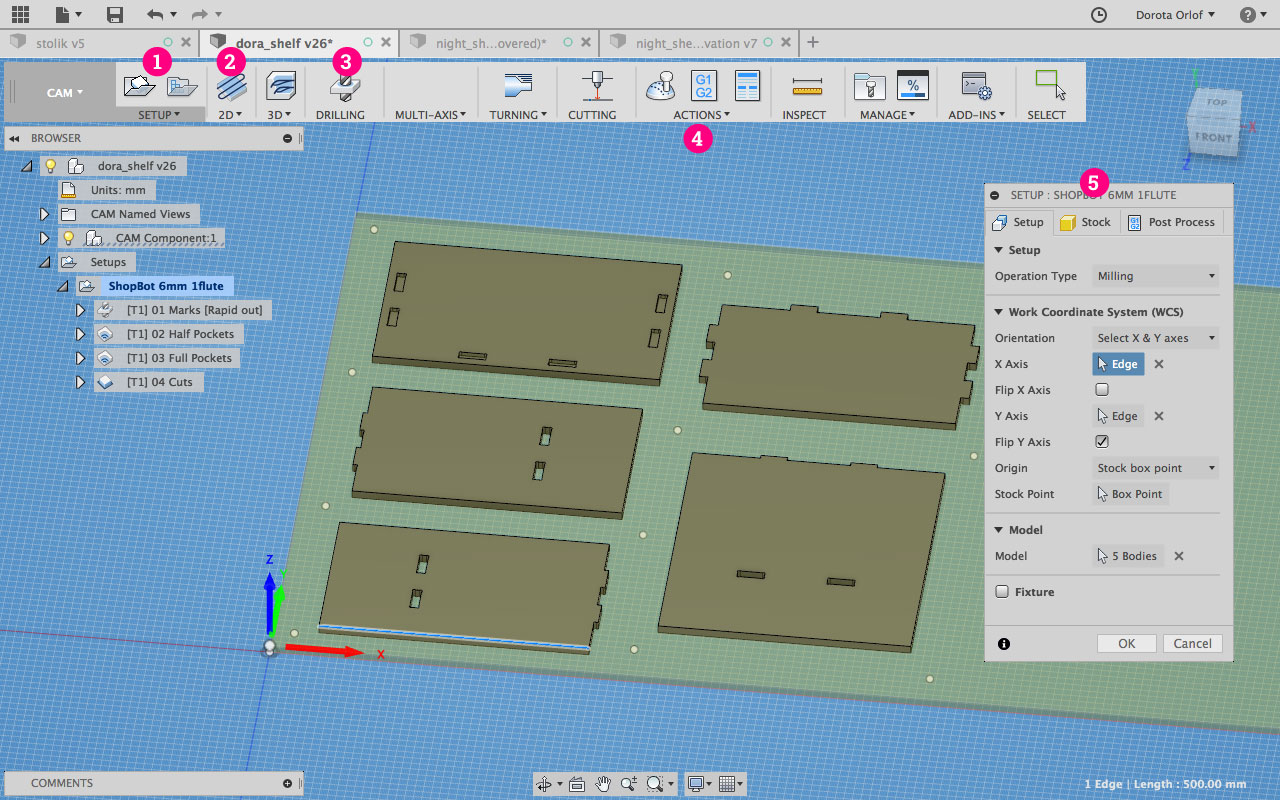
- Here I’m creating new setup for my job. The details are specified in the window on the right (nr 5).
- In this setup I’m creating the operations. I’n my case this are 2Do perations (pocketing, contouring) and driling operation (nr 3).
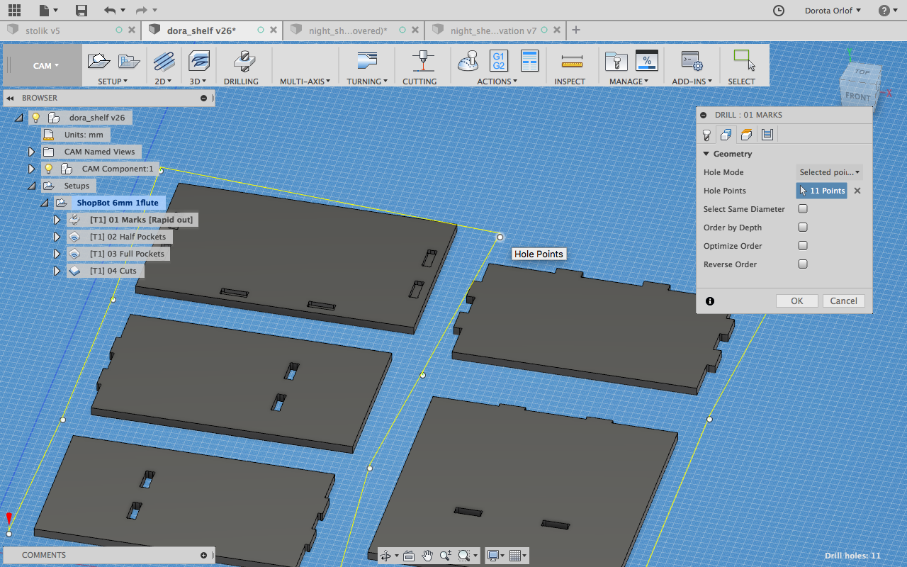
- Drilling strategy/operation
- Under Action menu one can find the feature
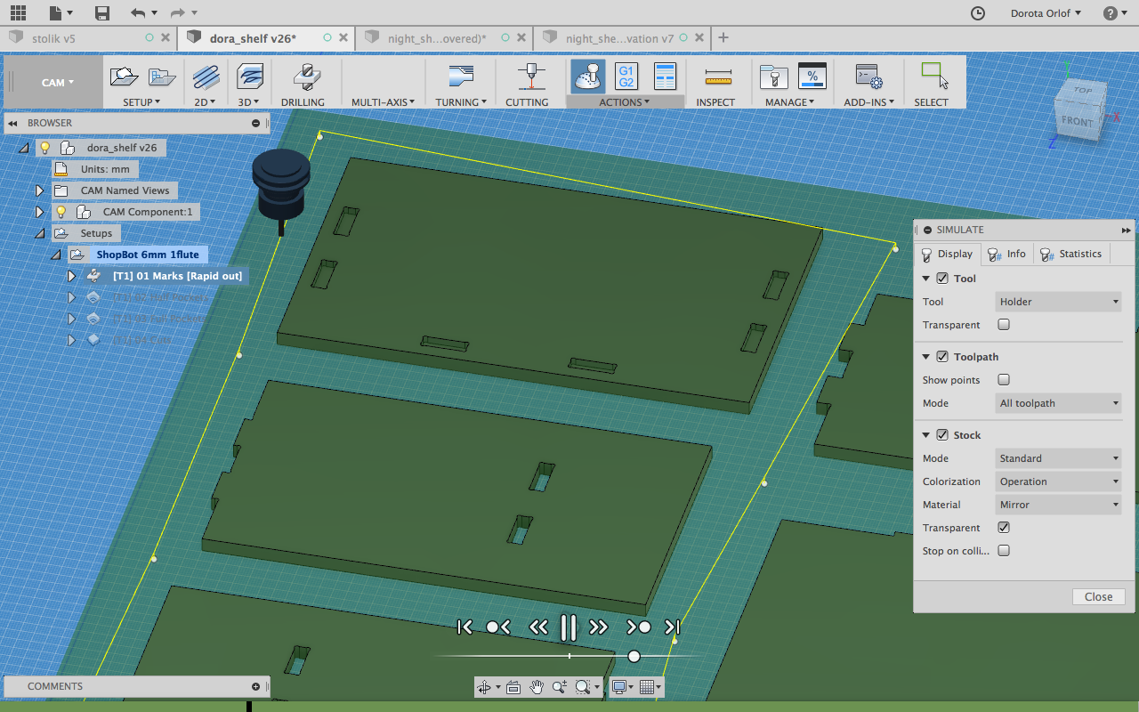
Symulationto prewiev which way the machine will go, how deep it will mill etc. One has to check it before exporting the files! - Feature window, with specification
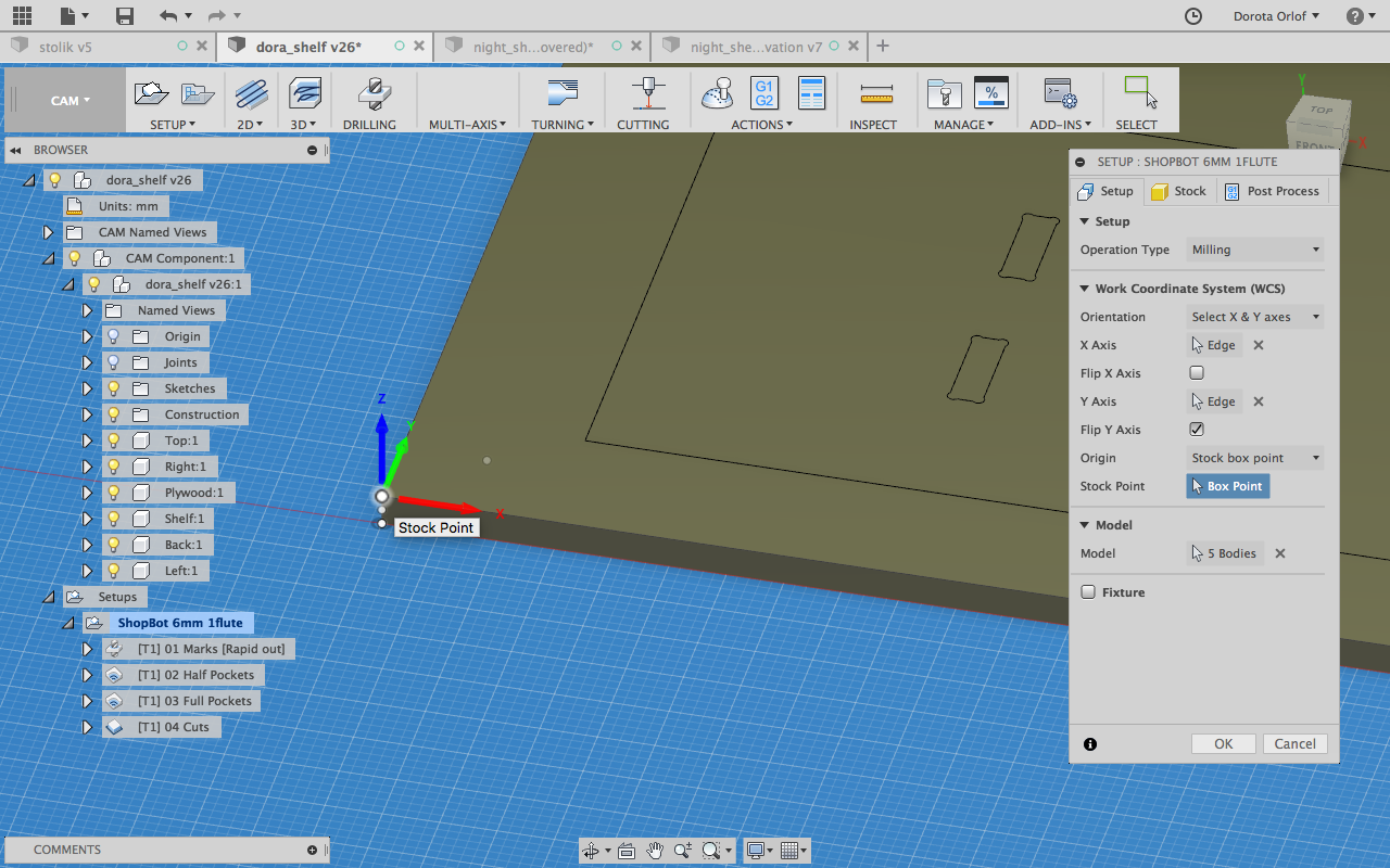
In Setup Window I’m choosing the origin, it should be on the top sufrace of the plate. It should be also synchronised with the origin on the ShopBot.
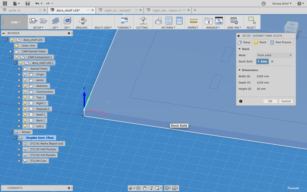
Next I’m choosing the stock which represent my plywood plate.
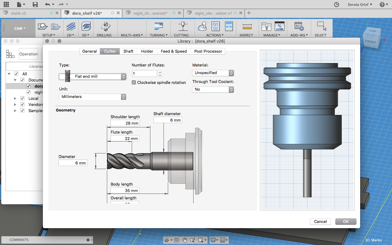
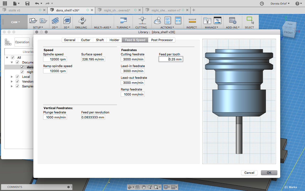
Than I’m adding the tool that I’m going to use for milling. From top menu I’m choosing Manage > Tool Library > New Mill Tool. We are using a 6mm flat-end mill, the feedrate and spindle speed I know from presentation that we’ve attended previousely. Usually the drillbits are spinning clockwise but it depends, one have to check how does it looks like.
Now comes time for defining strategies. First I want machine to drill the marks for screws that I’m going to use for fixing my plate to the sacrificial layer. It’s important so the plate wouldn't move while milling all the next operations. I’m making new drill operation and selecting previousely designed points - to mark where holes should be drilled.
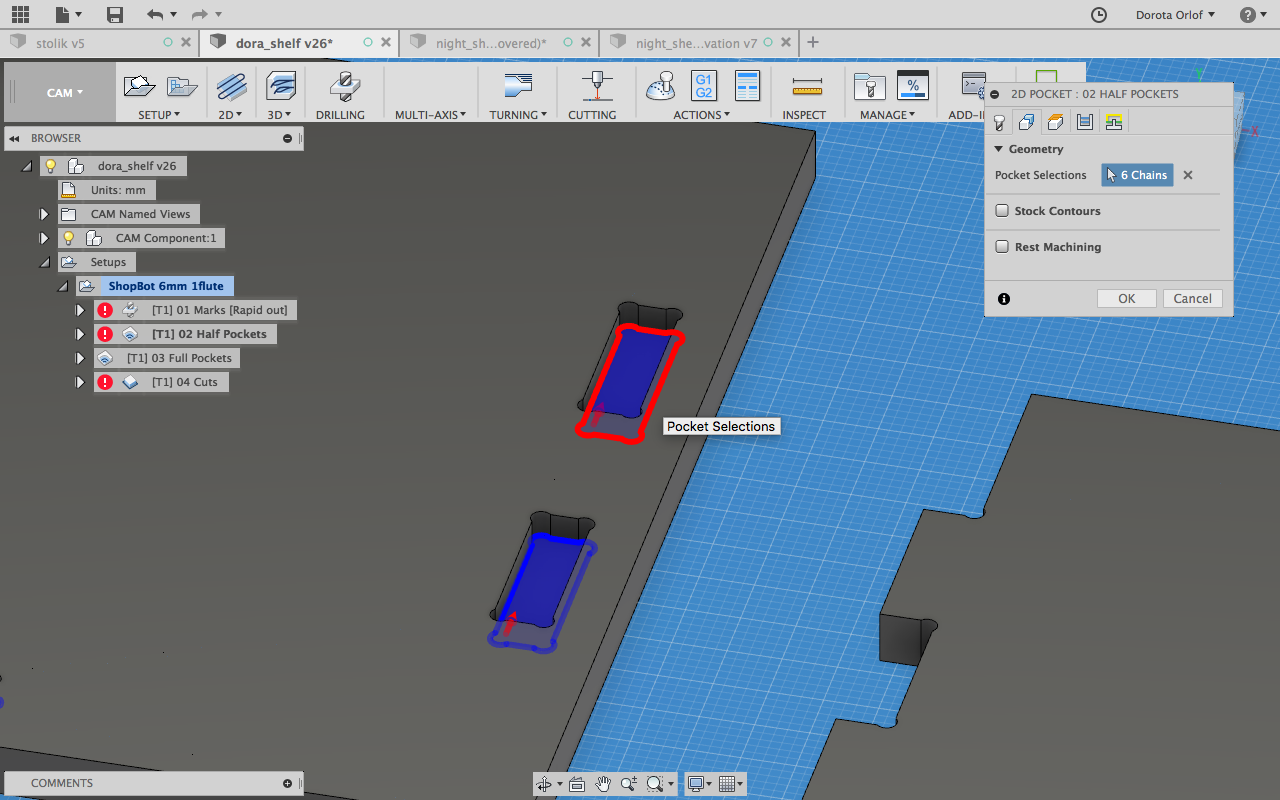
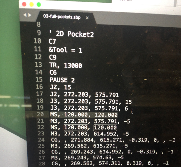
Next I’m adding two times 2D pocket operation: one for full pockets one for half pockets. While specifing pocketing operation for half-pockets it’s important to select the bottoms of the pockets, as in the screenshot below:
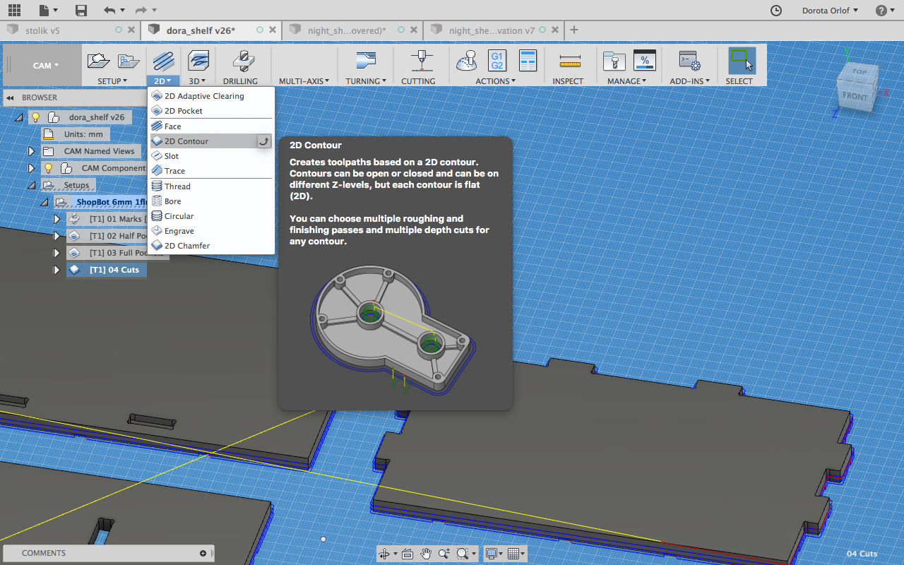
The last operation I’m going to add is cutting.
In the feature window one always has to choose previousely defined tool, and define such parameters as:
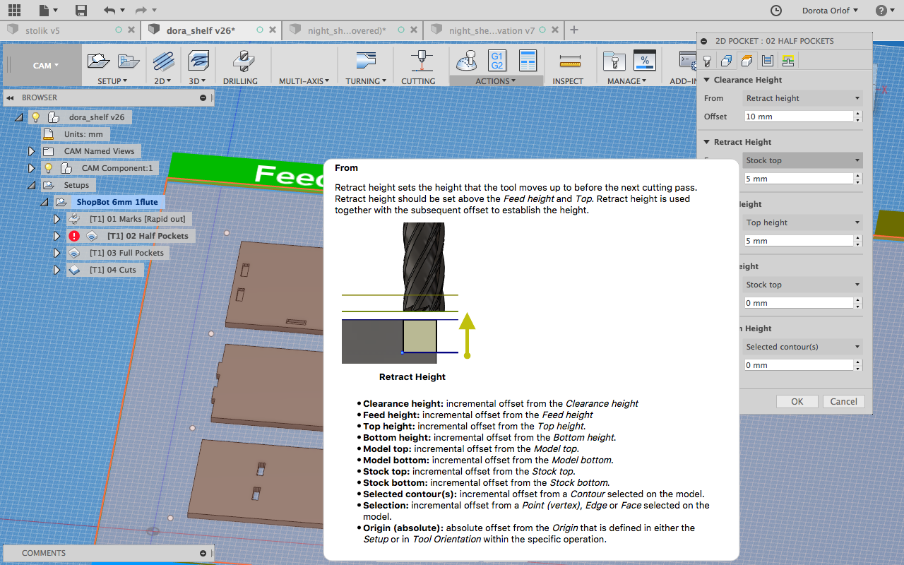
- Clearance Height - the tool traveling distance above the material when rapidly changing location: 10mm
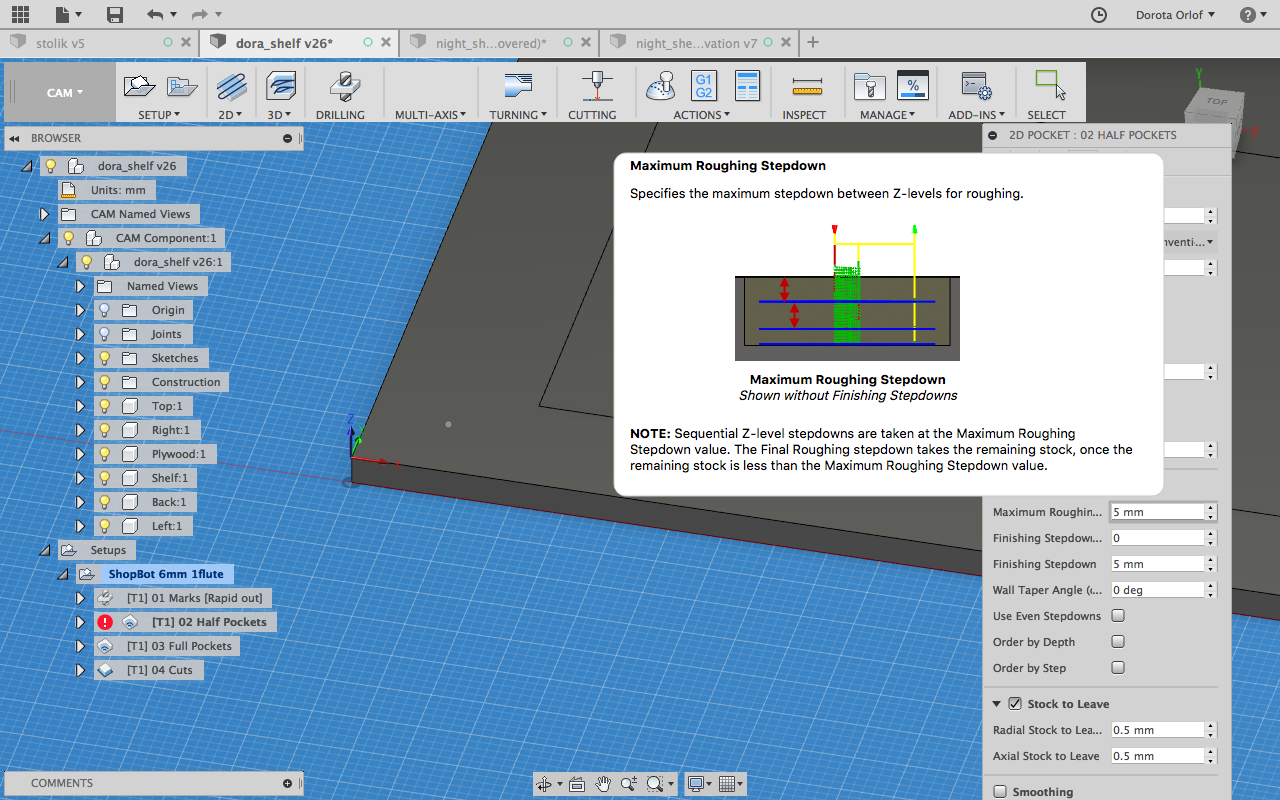
- Roughing Stepdown - the distance between passeson Z axis: 5mm
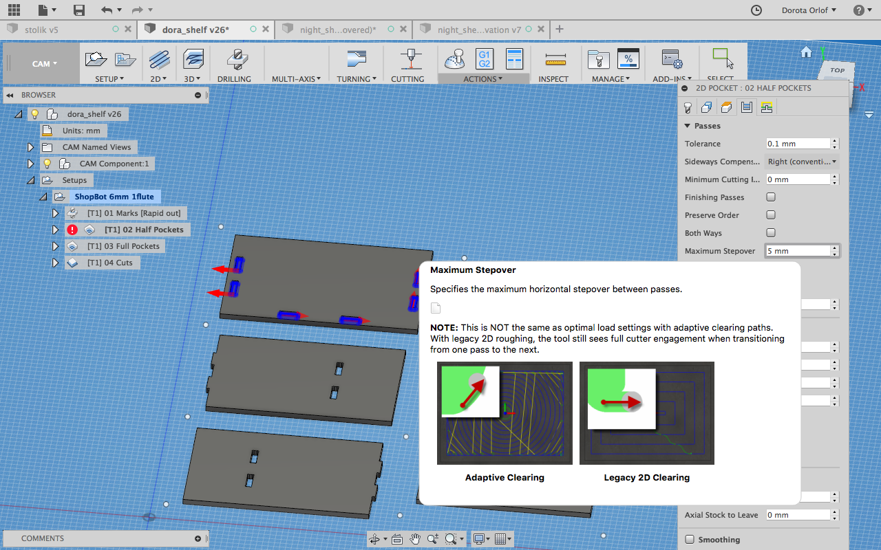
- Maximum Stepover - the distance between one pass on X,Y axis to another: 5mm
- Stock to leave - It’s mostly if you would like to leave some wood for finishing, I haven’t put it: stock to leave on x/y axis - 0. One should put a bit negative value on z-axis (-1.5 mm), so it will go below the bottom part of the surface and for sure will cut through (since the big sheet ofwood are likely to be uneven).

In the 2D Contour strategy in the feature window I have to set up tabs. This are the parts which are not going to be cutted through in order to keep the elements in their positions. I’m goint to remove them manually afterwards. To set them up I’m I’m marking the Tabs option and choosing their position.
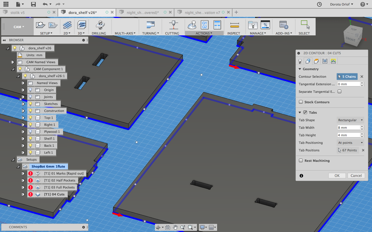
If you zoom-in you will see them in the symulation.
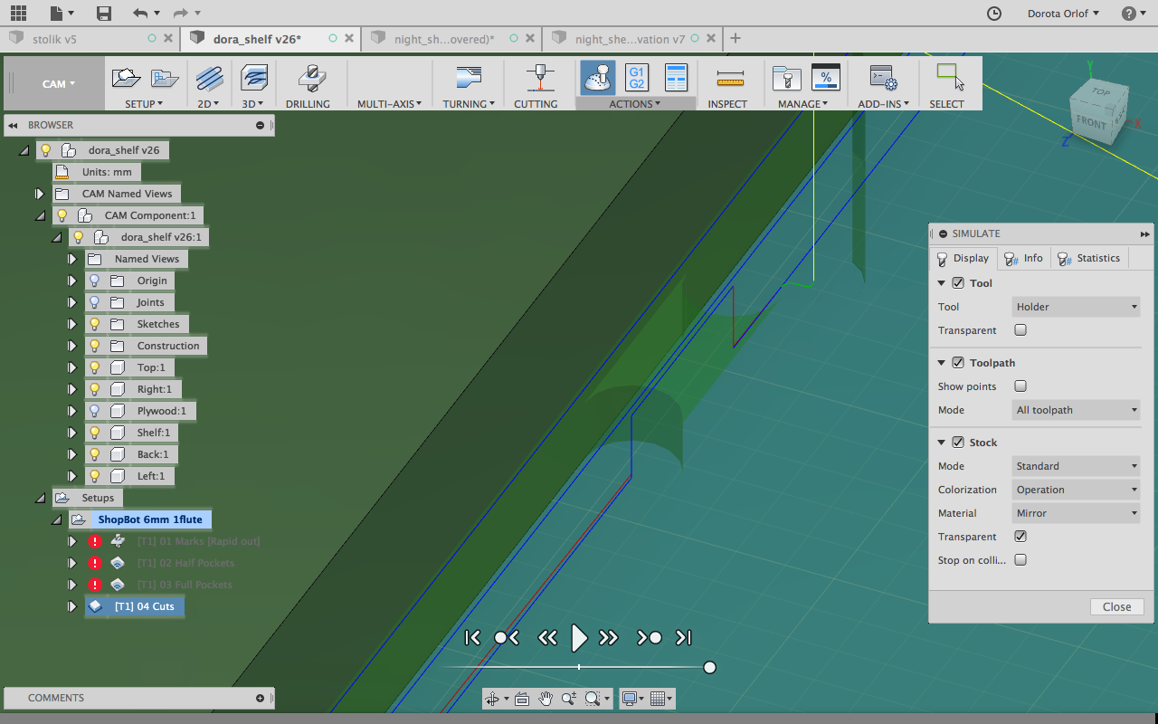
In next step I’m checking the symulations of each strategy, it’s good to make the stock visible in this case.
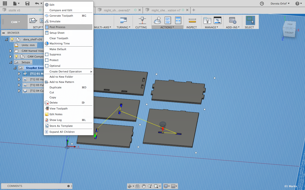
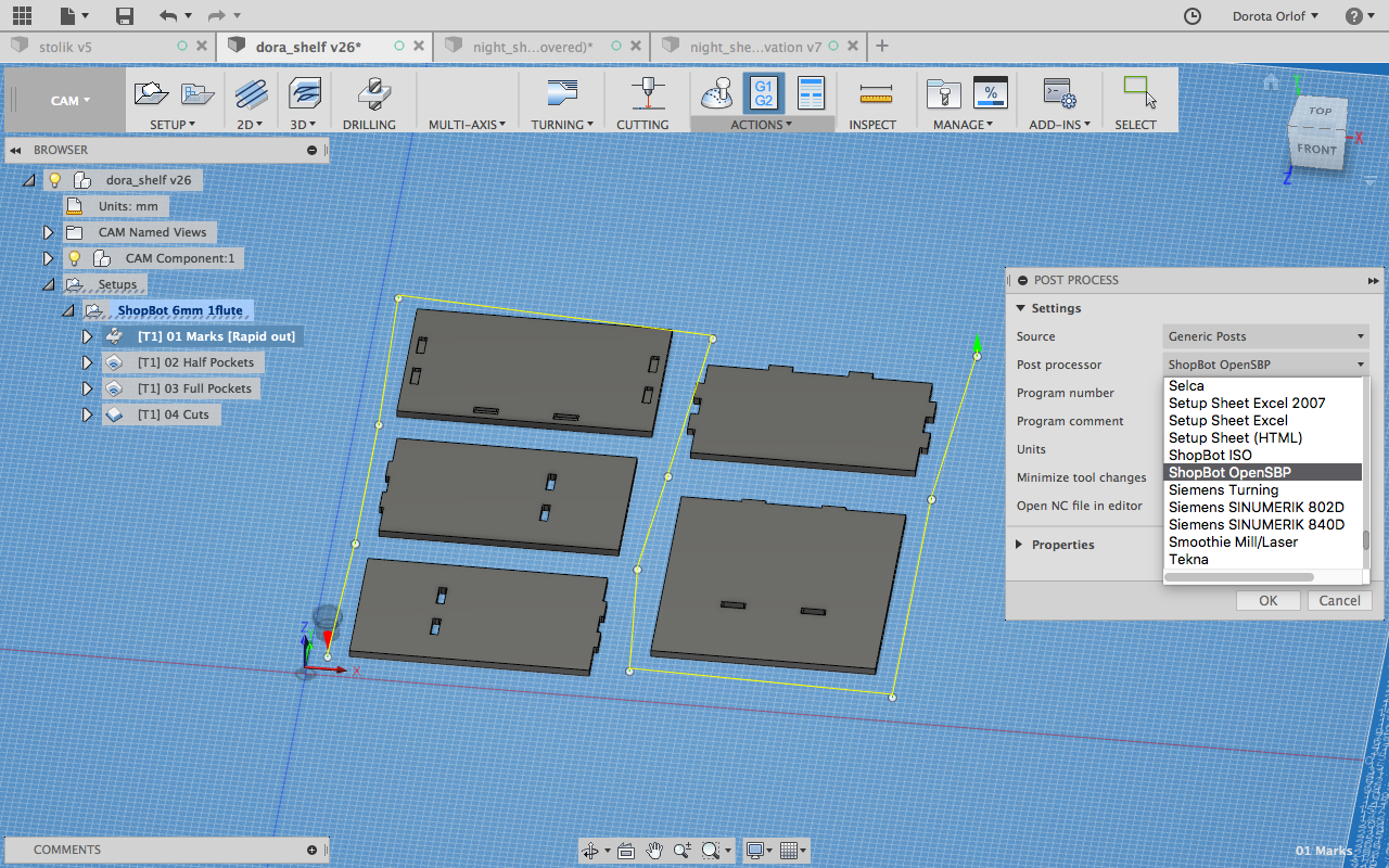
And getting to PostProcessing and creating the .sbp files. I’m giving the files numbers to run them in this order on the machine: 1. drilling, 2. half-pockets, 3. pockets, 4. cut
In our case we have to select ShopBot Open SBP Post Processor.
And now I can save them on USB stick and get to the machine!
I’d took part in demo of CNC, and have nice group documentation, nothing though bring you so much down to earth as trying things by yourself.
Here come the steps that one have follow to get CNC router working + some troubleshooting!
Managing the CNC router
Once you open the Shopbot software on the computer connected with the machine, you would face three windows for different cases:
CommandConsole
Gray window, there is a top menu from where you can run the commands. Most used ones:
Cuts > C3 - zeroing the absolute position - the spindle is moving back to the default absolute position which on shopbot is on bottom-right corner.
Cuts > C2 - z axis calibration with “zero plate” and aligator clips - after running that the z axis is automatically fixed. One has to put the aligator clips on the ring surrounding the drillbit holder. Than follow the instructions displayed on the screen (which is putting the metal plate underneath, and pressing ok). The z-axis will be adjusted automatically.
- File > load partial files - here you are choosing the strategy to run.
The best order to run strategies is:
-drilling the holes for fixing the plate on the sacrificial sufrace
-milling half-pockets
-milling pockets
-cutting outline (cutting should be done at the end since the cutted out parts can move and one can break the drillbit)
After loading partial file software will display the information (pop up, yellowish page with informations) - hit enter (even though there is no “ok” button). Than you will get the notification - start spindle - press big green button on joystick and hit enter for ok.
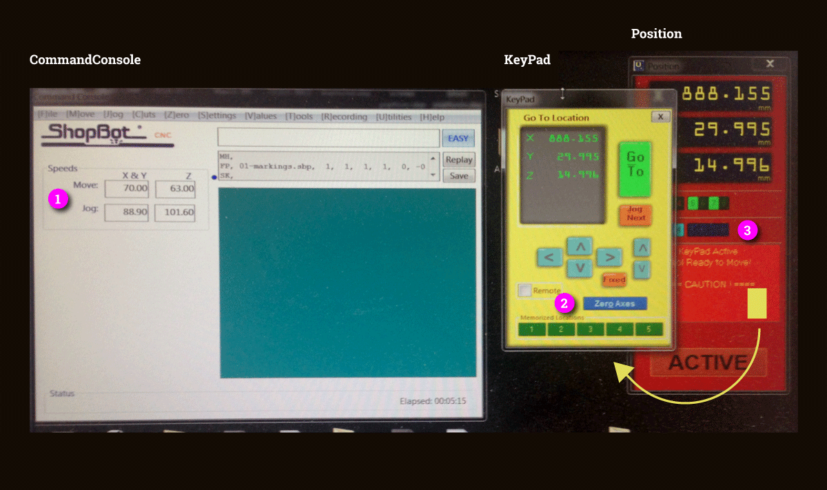
Another part of the CommandConsole is:
- Move and Jog speed values window - nr 1 at the photo above. This is where the values set up in CAM shuld be displayed.
If you use Fusion CAM double check that. There is somewhing wrong in saving the G-Code and customised values are being overwriten with some other values
The values that are working for shopbot are (in my case):
- Move Speed: 120.000(x/y) 120.000(z)
- Jog Speed: 30.480(x/y) 10.160(z)
Before running the file one has to open the G-code file and check if the MS (Move Speed) and JS (Jog Speed) are matching. If the don’t one has to overwritethem in G-code and save.
Shopbot G-code reference: http://www.shopbottools.com/ShopBotDocs/files/ComRef.pdf
Position
Red box. From here one can change the drillbit. To do so one has to press the number3from blue buttons fromOutput list(nr 3 on the photo). This command will release the vacuum which is keeping the tool. One person should keep the hand on it so it wouldnt fall down completely and break. You remove the old drillbit, put the new one and press 3 again for vacuuming it and fixing.Keypad
Yellow box, which is popping up from red one afterpressing the minature.
Bu using the arrowsone can move manually the axises. If you’d like to start the job not in the default position of z/y,you have to navigate there and pressZero Axes(nr 2 on the photo) than mark x and y as ones to be fixed. For fixing z axis one have to go to the Position box - red one.
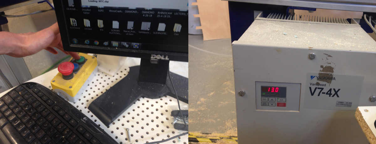
There is also a joystick with three buttons for controlling the main actions: start/reset/stop. On the display on the side ofthe shopbot the spindle speed is being displayed.
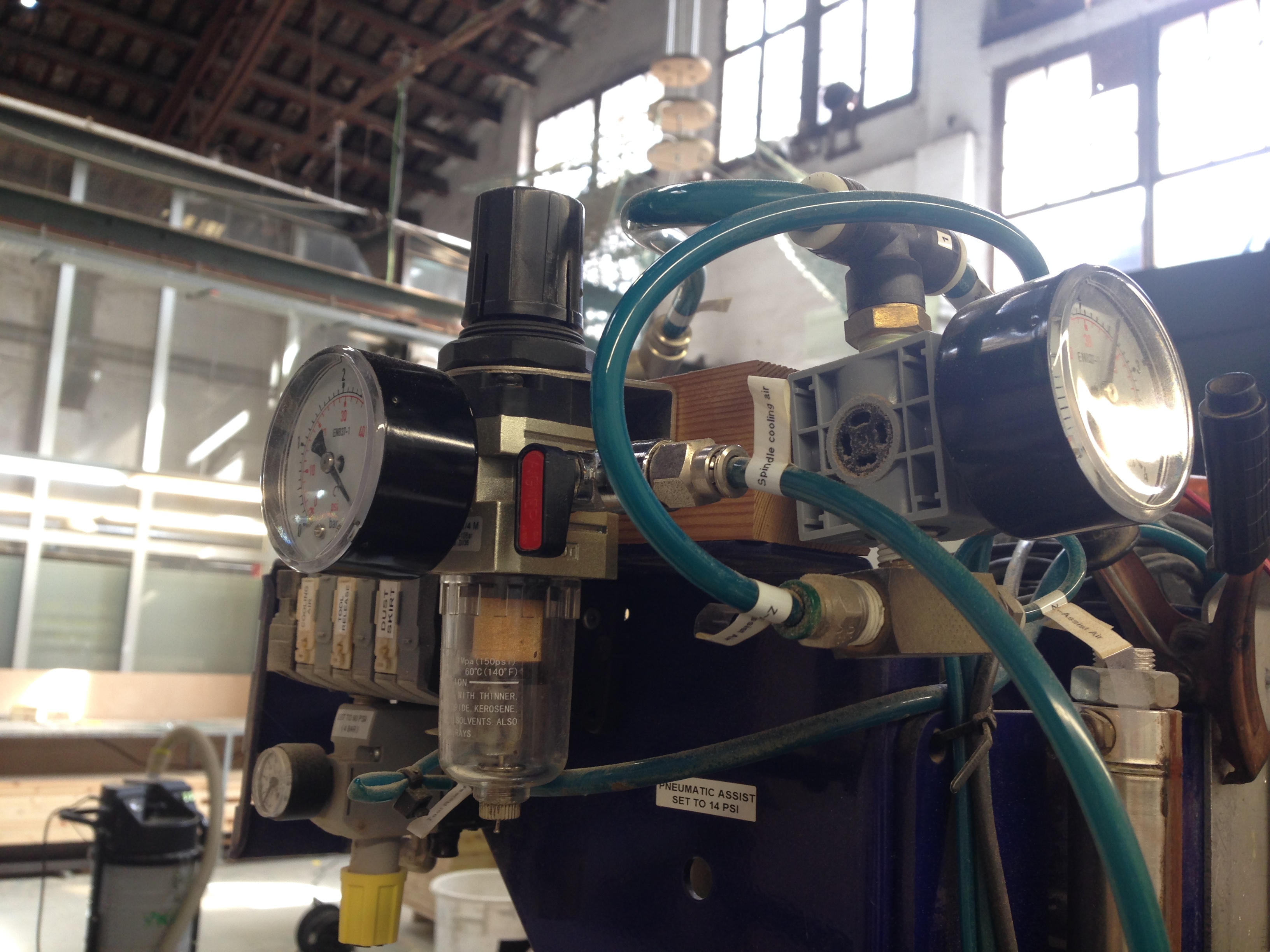
Before starting turn on the air-pressure pump - red switch on photo above.
Knowing all of that we can start!
- Put the material on the build plane of the machine.
- Set the origin of the milling machine. X and y manually and fix by pressing “zero axes”, C2 for z-axis.
- Go with z a bit up before starting
- Use the screw marking strategy.
- Screw the screws in marked places (starting from inside of the plate).
- Run other strategies as following: half-pocketing, pocketing, cutting.
- After finishing vacuum the wood-dustand unscrew plate (from the center)
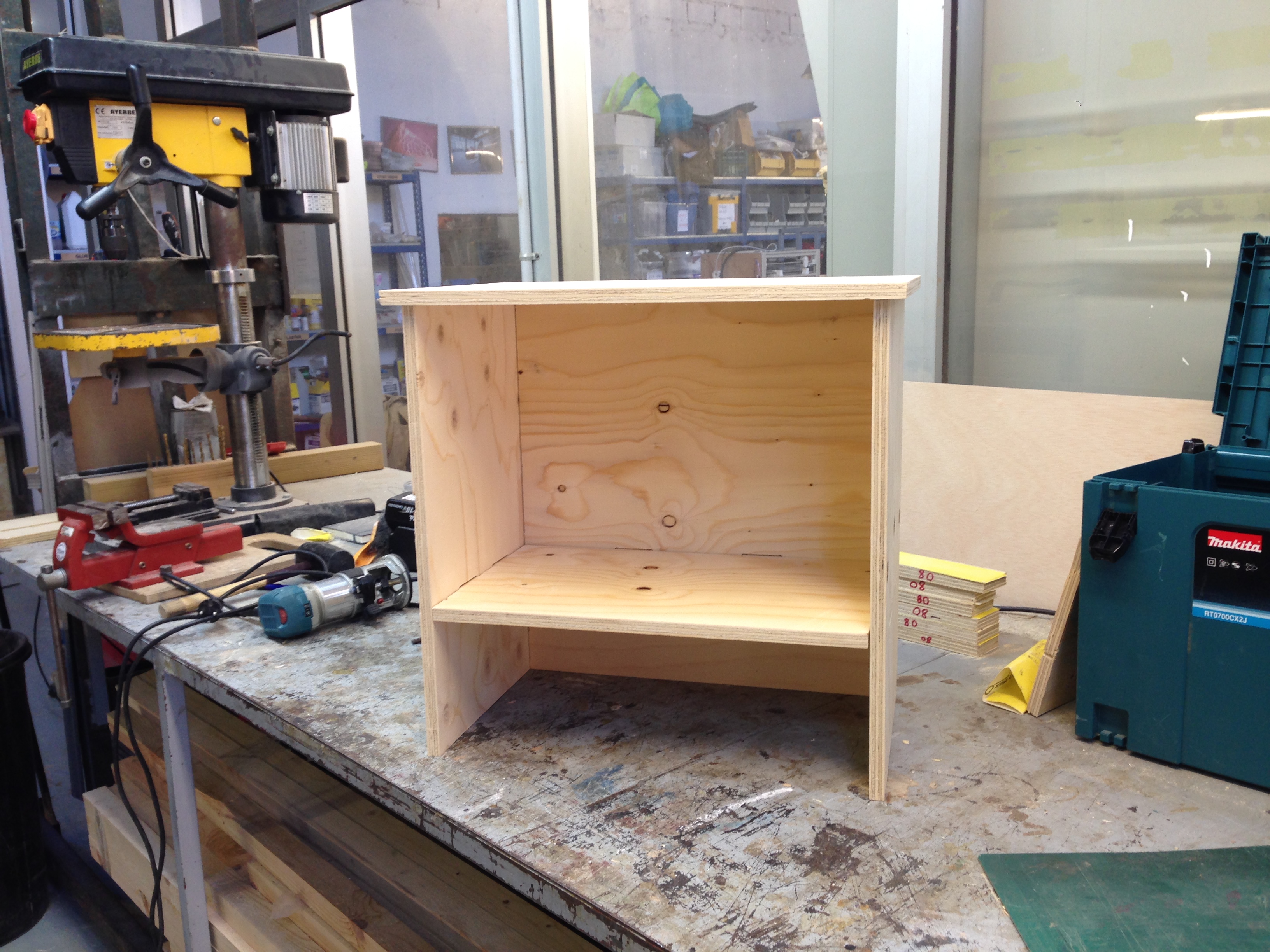
Now a bit of polishing:
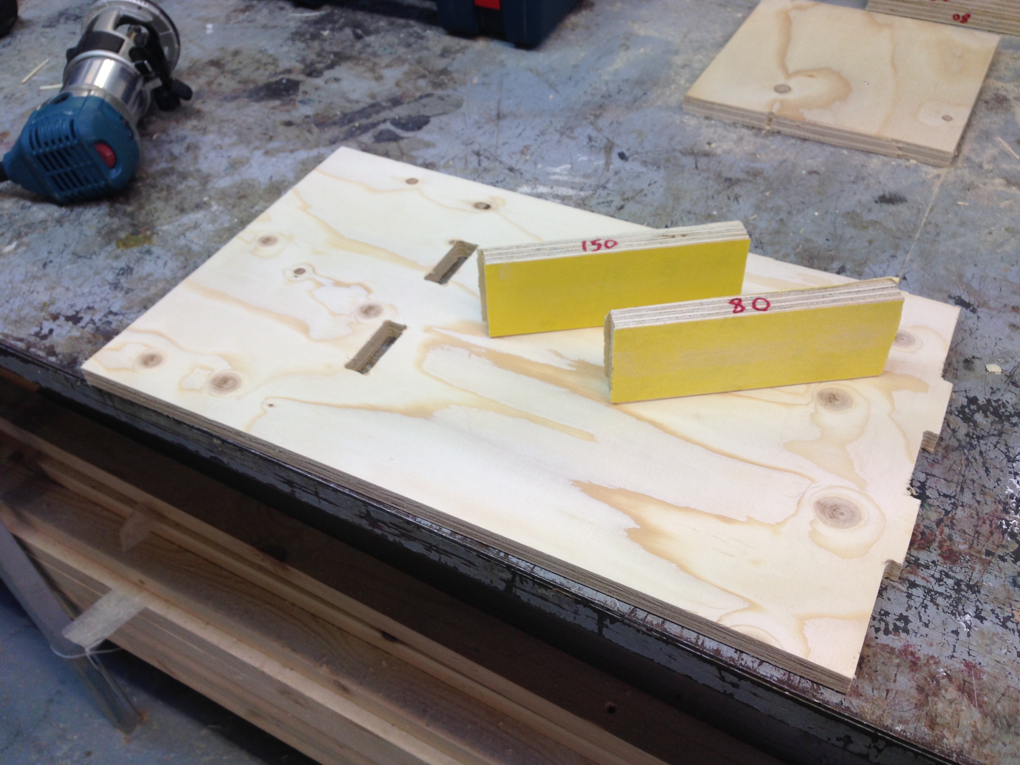
Putthe plate on the hockers and cut in between the tabs (which are keeping the elements in place) andthe restof theplate by using a thin-blade saw. Afterwards get rid oftabs by using the circular-spindle tool
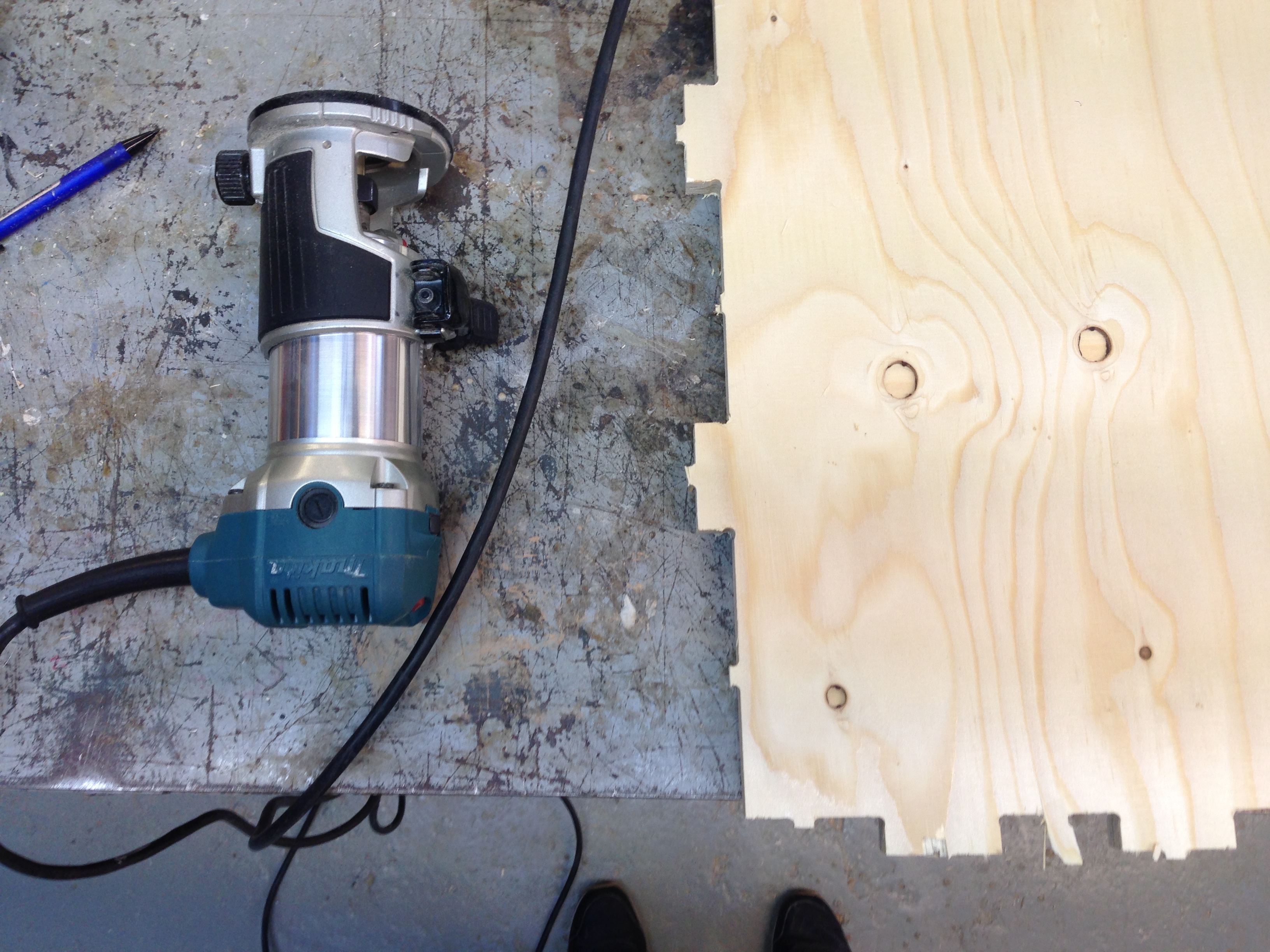
Now time for sanding
And assambling!
Files made during this assignment: