Embedded programming
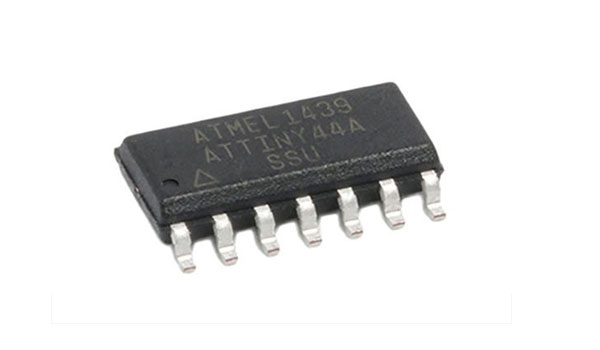
First partof this week Assignment is to read a micro-controller data sheet: ATtiny44A Datasheet
In upcoming weeks we are going to work a lot with AtTiny microcontrollers, so it’s good to know a bit about them.
This datasheet is very tricky for a person who doesn’t know anything about electronics (except experiences made in last weeks!),becouseof the dry language and format. Still I’ve managed to pull-out some accesible informations!
General Features of AtTiny44:
The ATTiny44 is high Performance, low Power 8-bit Microcontroller with advanced RISC architecture. It’s features:
- 4K Bytes of Flash Program Memory
- 256 Bytes of Programmable EEPROM
- 256 bytes SRAM
- 12 general purpose I/O lines
- 32 general purpose working registers and 8-channel 10-bit ADC.
- Internal calibrated oscillator
- Operating voltage supply between 1.8 ~ 5.5V.
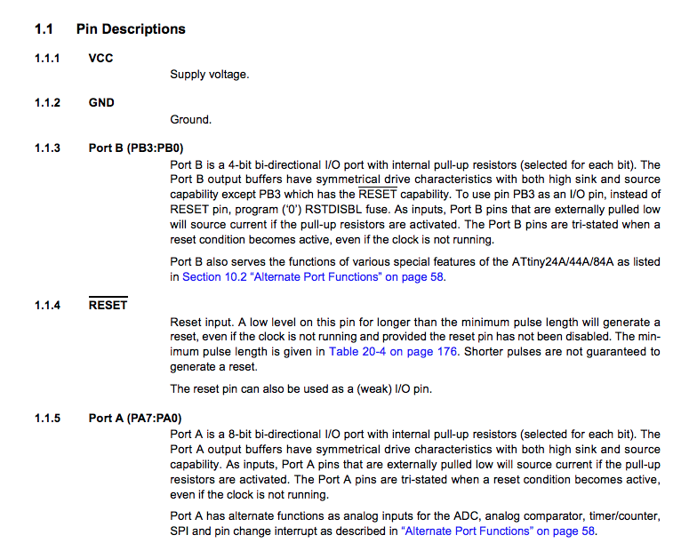
It has two kinds of ports:
Port A pins are 8-bit bi-directional I/O port with internal pull-up resistors (pin names are from PA0 to PA7)
and Port B pins are 4-bit bi-directional I/O port with internal pull-up resistors(pin names are from PB0 to PB3).
Pin configuration: necessary knowledge while building the circuit and connectimng the electronics
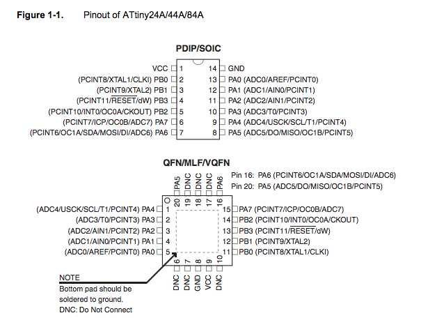
Pins description there are pins which are ment for a specific use,and other to which you can assign the function
Now second part of an assignment: Program your board to do something, with as many different programming languages and programming environments as possible.
I will set my Begnners challlenge for programming my board with use of Serial Communication!
Software serial multple serial test
After Wikipedia:
Serial communication is the process of sending data one bit at a time, sequentially, over a communication channel or computer bus.
Im going to send a signal from my board, which will be pressing the button. Every time I press it, in Serial Monitor I’m going to get message “Button” printed out.
To do so I will include in my code SoftwareSerial library.
#include <SoftwareSerial.h>
Next I’m defining the pins for Serial Communication: RX stays for receiver and TX for transmitter.
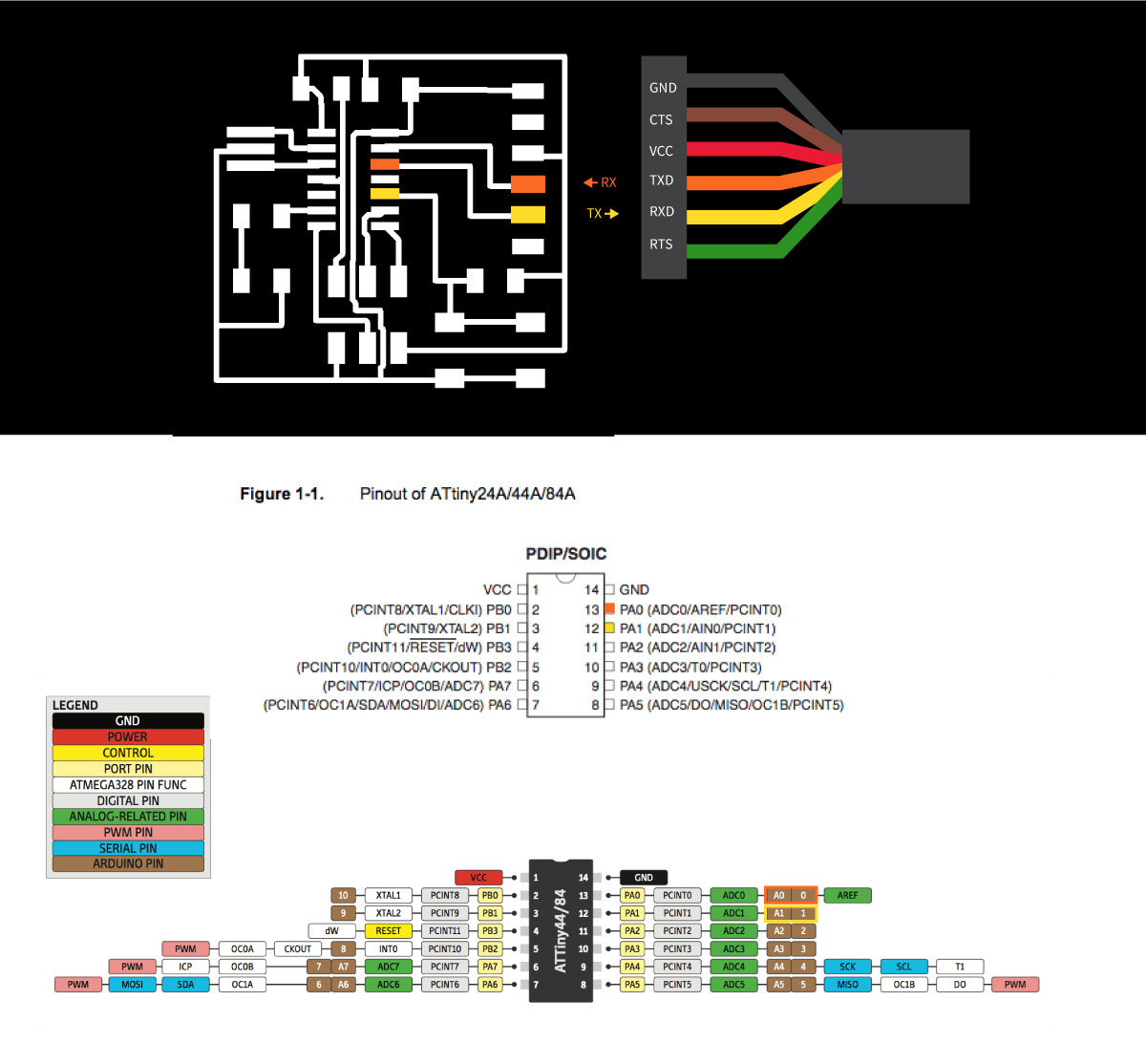
I’m coming back to the schematics and board design of the PCB board that I’ve created during theElectronics Design assignment
Having the knowledge (from datasheet) about the Pisnouts of Attiny 44, I’m spotting the TX and RX for pins 0 and 1 (marked with orange and yellow color below).
mySerial(0, 1) - we define the pin for RX, TX
Next step I’m making a setup, which means defining a general behaviours:
bool buttonDown = false;

void setup() {
  mySerial.begin(4800);
  mySerial.println("Hello, world?");
}
Than comes a time for defining the loop behaviour, the things inside the loop will be happening over and over:
void loop() {
  bool buttonReleased = digitalRead(3);

  if(buttonReleased){
    buttonDown = false;
  }else{
    if(!buttonDown){
      mySerial.println("Button");
    }
    buttonDown = true;
  }

  if (mySerial.available()) {
    mySerial.write(mySerial.read());
  }
  if (mySerial.available()) {
    mySerial.write(mySerial.read());
  }
}
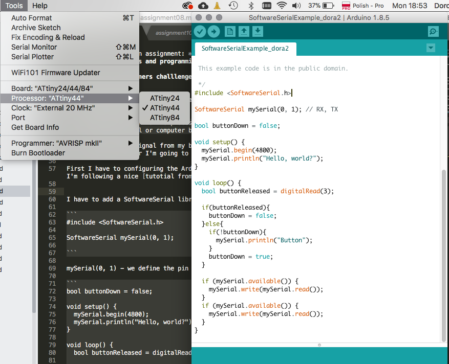
Before start burning the code I have to configuring the Arduino IDE to program AtTiny microcontrollers. For doing that I’m following a nice tutotial from high-low tech
Now I should be able to choose my microcontroller from the list under the Tools menu.
Than I’m uploadingte code and testing!
Useful links:
Great introduction to AVR, C and Arduino:
Files made during this assignment: