Output devices
There is so many options to explore in this topic: vibrating mootors, stepper motors, muscle flexinol wires, speakers, screens, led arrays…Wanna try allof them! But let’s be serious - for this assignment I’m choosing to work with mini vibration motor. I’m going to use them in my final project, and also - want to make my silicone flat fish crawl.
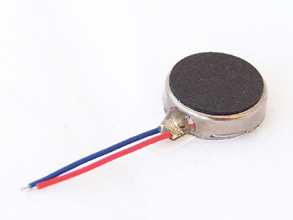
Vibration motor: https://www.digikey.com/catalog/en/partgroup/mini-vibration-motor/58884
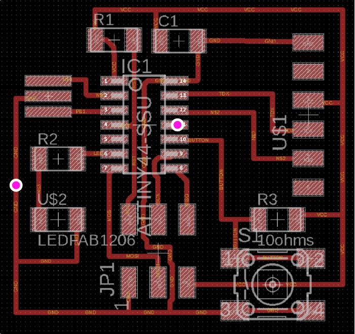
It’s a DC motor so I can make it work by connecting to the voltage and ground. I’m going to use for that my previousely made board with the button and led. I’m going to do it in a pretty unaesthetical way (to see if it’s working) and solder the cables directly to empty pin and ground trace. There is a nice empty pin (marked with one of pink circles on pic below) this is where I’m going to solder my cable for voltage. The other cable will be soldered to the trace.
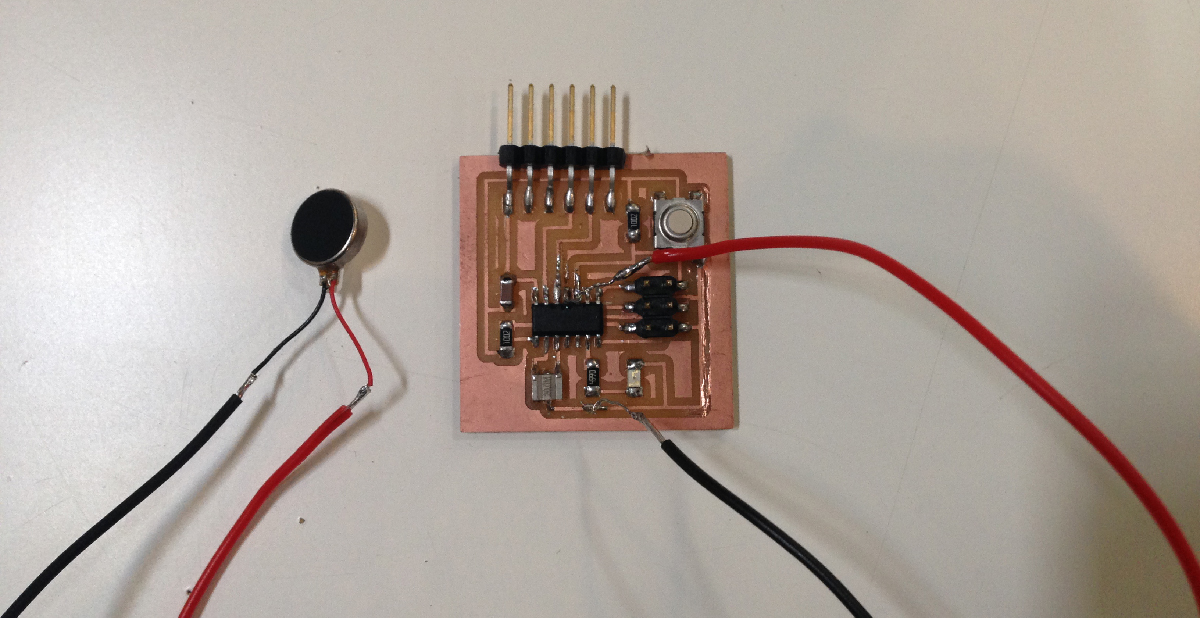
The wires from the motor are too thick to solder them directly to tiny pin and a trace, I haveto extend the wires with some tinier ones (by soldering them together).
Now I’m going to rework my previousely written code for button and led, which means basically to switch the outputfrol LED to vibration motor,the rest stays the same.
pinMode(vibPin, OUTPUT);
pinMode(buttonPin, INPUT)
Uploading to the board and…wheneverI’m pressing the button now the fish crawl!
Now I would like to connect three DC vibration motors to one board, I’m planningt integrate it to my final project!
I’m ging to use vibration motor.
I’m going to base my PCB traces design on Neil’s speaker board. First I’m going to connect one motor.
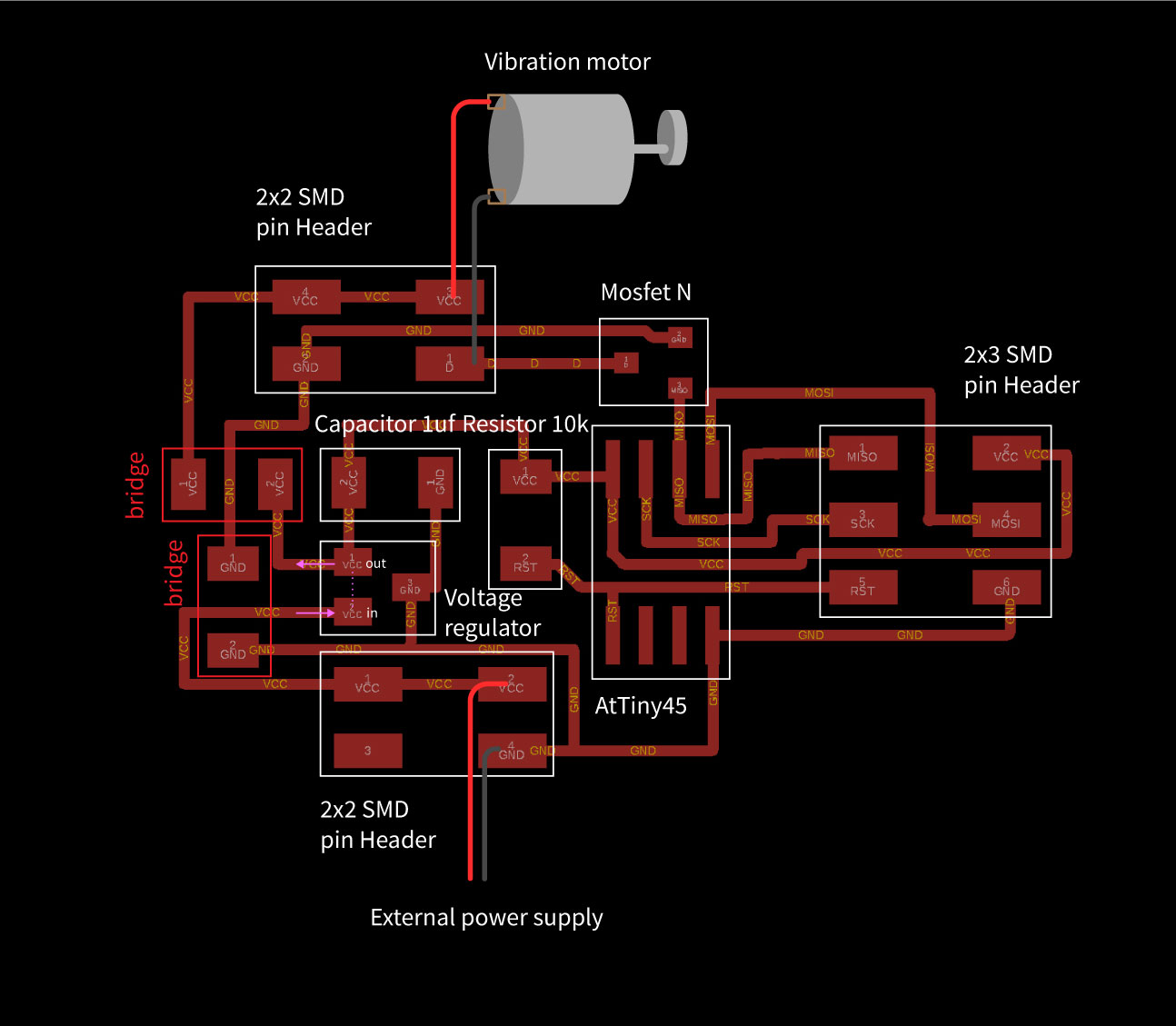
As in speaker example I’ve put a Voltage regulator 5V / 0.1A, which means that afte crossing this component the voltage comingg from extarnal power source will be reduced to 5 Volts. So isnot going to burn th microchip.
Mosfet N is kind of a switch, which by opening and closing will be switching on and off my vibration motor.
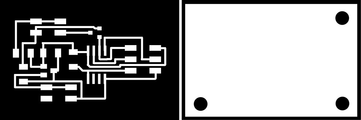
I’m exporting PCB design in .png format from Eagle. Than I’m going through thanks-God-now-already-well-known process of generating the .rml files in MODS. I’ve added the cuts for holes since I’m already thinking how to imtegrate it in my final project.
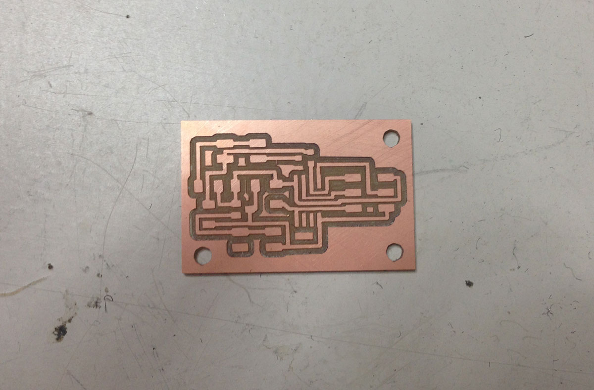
Afterwards milling and soldering!
Milling PCB:
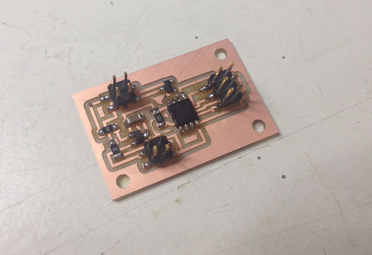
Soldering process:
Aaaaaaaand…have it!
Programming output board
I’m going to rework the Blink code from Arduino examples.
What I’m going to change is the pin number for an output, and naming.
const int vibPin =  1;

int vibState = LOW;

unsigned long previousMillis = 0;
const long interval = 2000;

void setup() {
  pinMode(vibPin, OUTPUT);
}

void loop() {

  unsigned long currentMillis = millis();

  if (currentMillis - previousMillis >= interval) {
    previousMillis = currentMillis;

    if (vibState == LOW) {
      vibState = HIGH;
    } else {
      vibState = LOW;
    }

    digitalWrite(vibPin, vibState);
  }
}
Now burning the bootloader and uploading the code. I’m giving the 5V through FTDI cable extended with jumper cables.
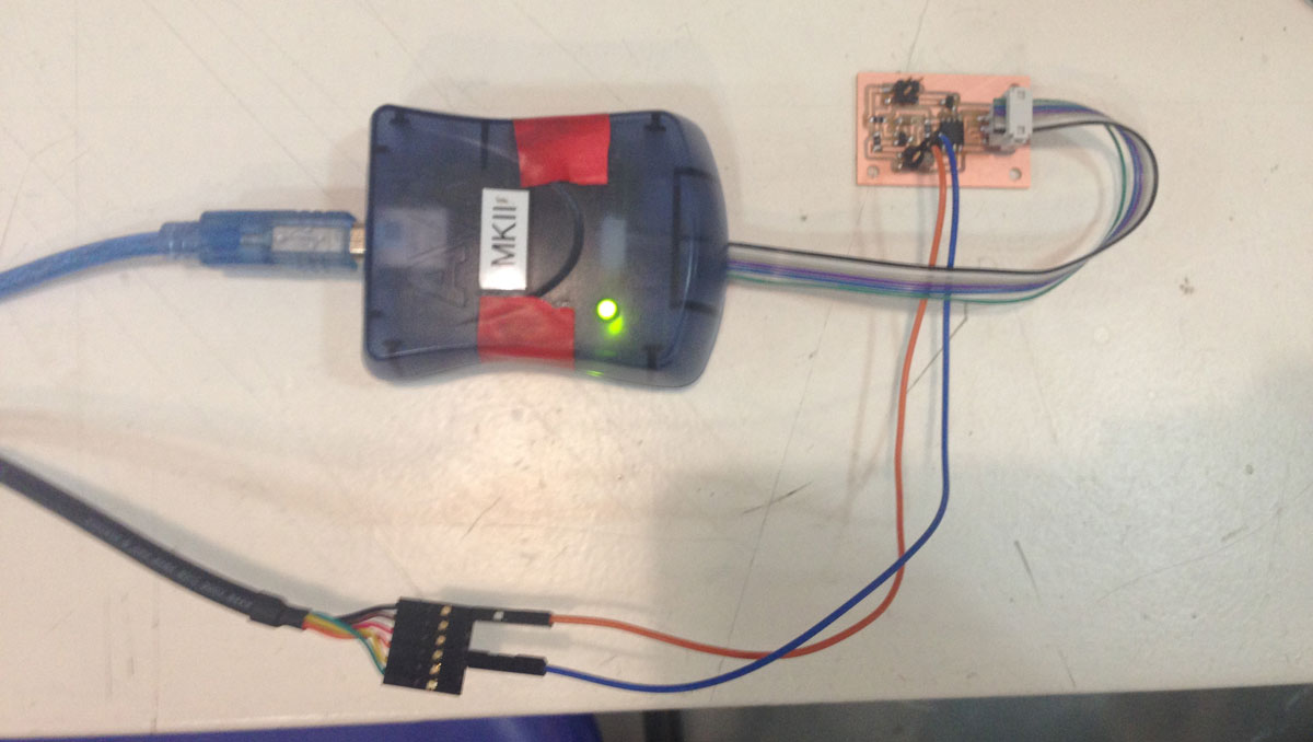
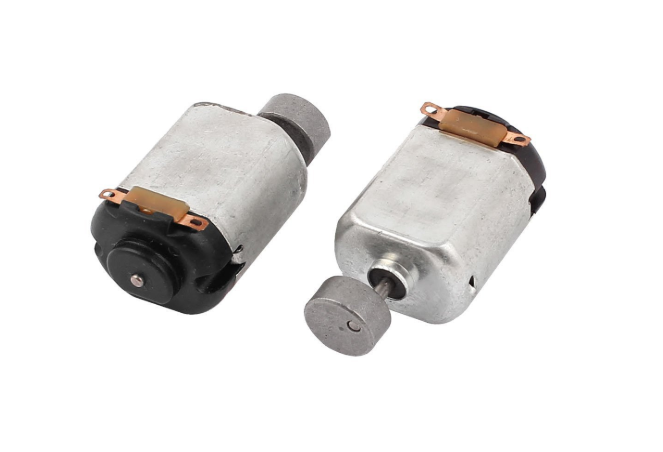
Now moment of truth….and not working. After testing I’m finding out that the motor is a problem. I’m replacing with another one and yes!
The new motor didn’t had a cup which was creating vibrating behaviour, I have to manufacture it later. But for now I’m happy that it works!
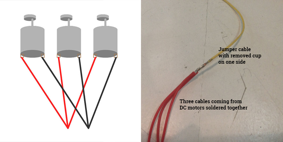
Now I’m wiring together three motors and checking if they would work with 5Volts charger.
I’m going to connect motors to one pin, so I have to wire them like in schematic underneath:
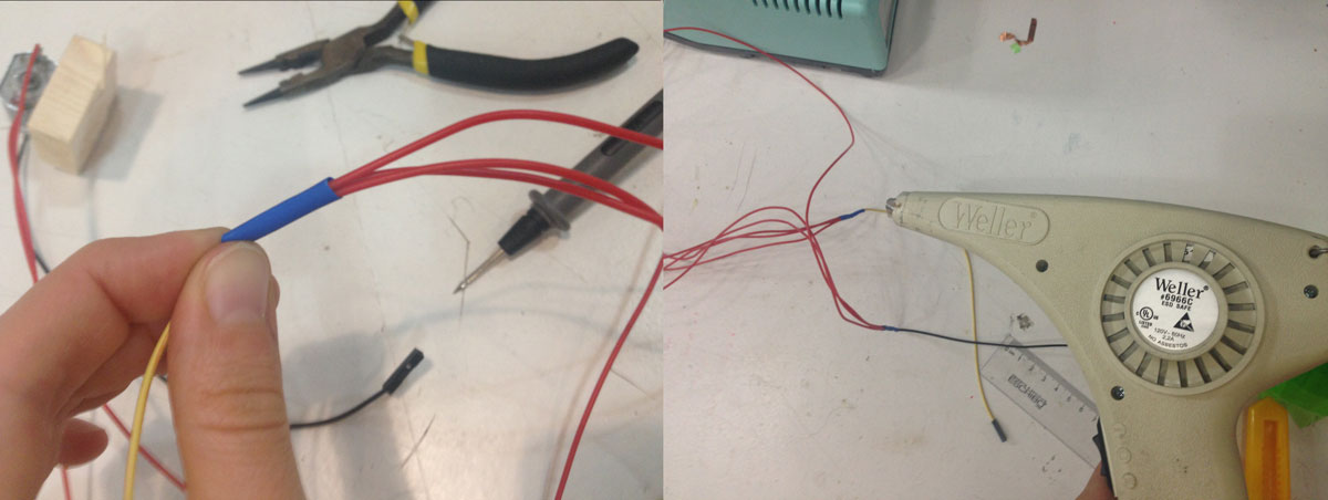
I’m stabilising and securing the joint with use of Heat Shrink Tubes
They are kind of working but with uneven speed and seems like they need a whle to warm up. I guess I will need more power!
Anotherthing is thatI’ve found out that becouse I’ve put the voltage regulator on the way from powersupply to the motors, they are never going to get more than 5 Volts! Ahh…I guess for the final project I have to redesign the board!
Files made during this assignment:
eagle file output board
pngs for MODS
rml files for milling
Arduino code vibration motor