Final Project
I’m not shaving - interactive installation
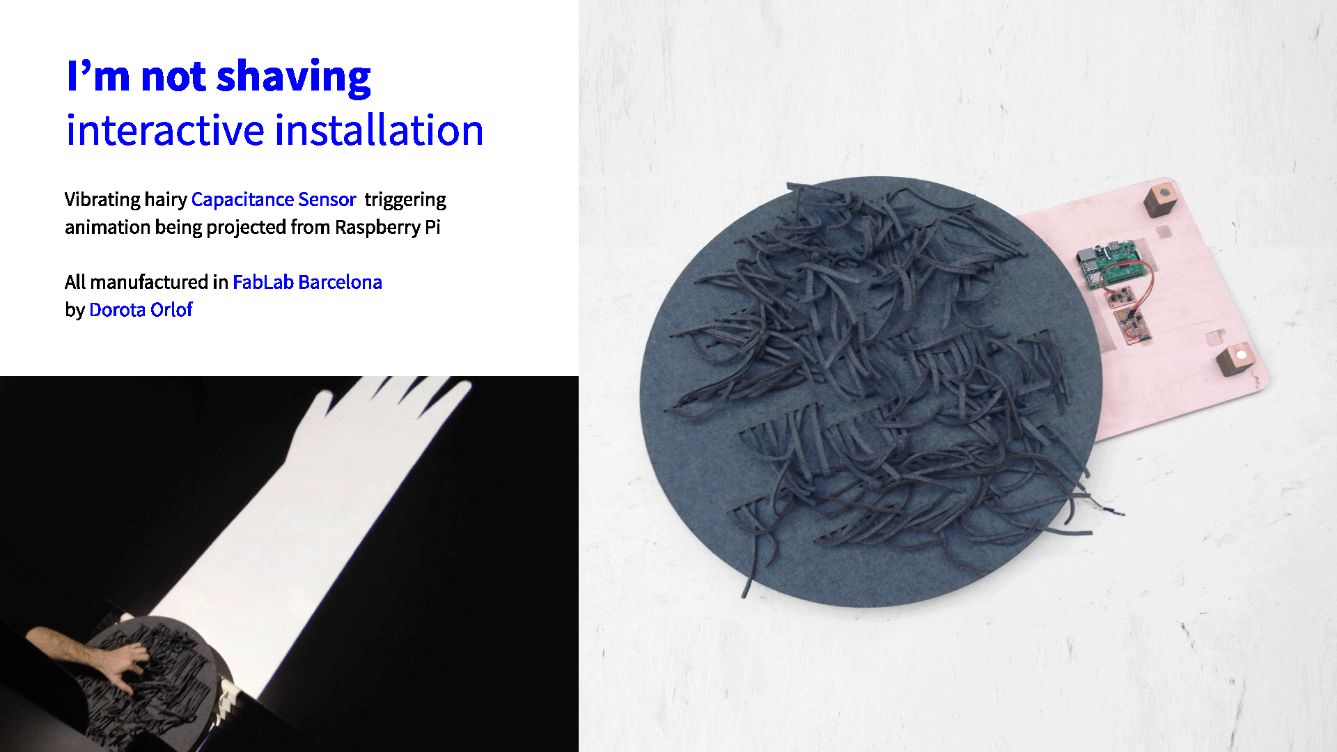
From the will of getting out of 2D mostly virtual canvas, and from the interest in urban art I came up with an idea of final Fab Academy project. It will be a participatory big size illustration, setted up in an architectonical space. The interaction with the user will make the static composition “alive”, making in the same time the user a part of the story.
In more practical words:
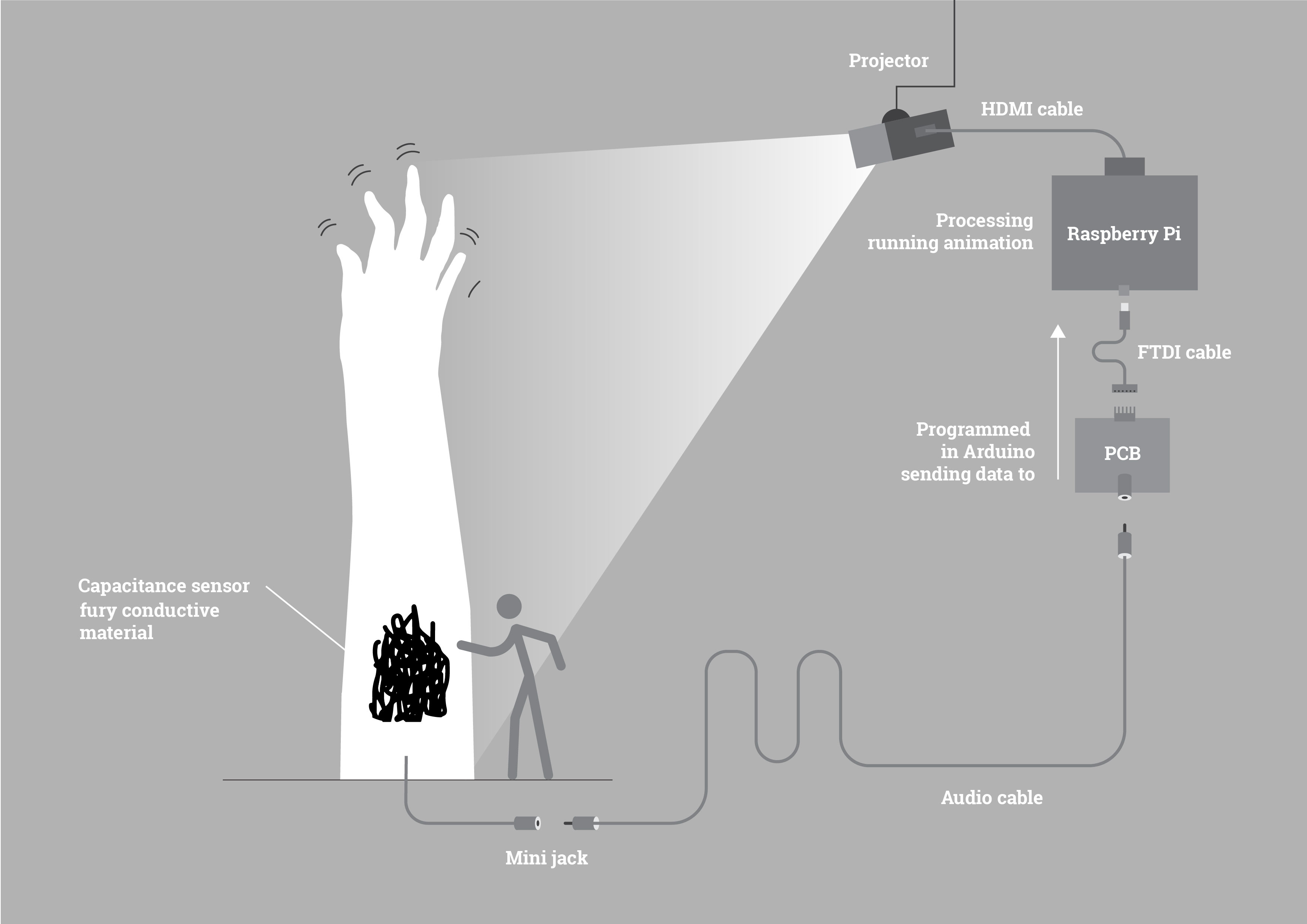
The installation will contains of two major elements: a capacitance sensor and a projected animation. The animation sequence will be player once the user will trigger the capacitance sensor by touching it.
Story
Generally it’s a funny story. There is a huge hand in idle state projected on the wall, in the place of armpit there is a fury-like capacitance sensor playing role of hair. Once you rub the hair the hand starts to move the fingers, like after tickling.
Furry capacitance sensor
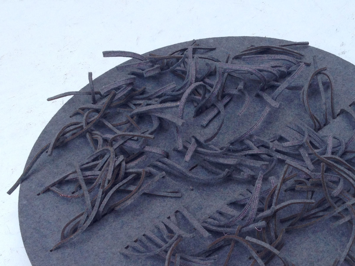
Capacitance sensor itself will be made from industrial felt sewed with conductive thread. I would like to build a soft, nice in touch sensor, remaining hairy structure.
I’ve choosen to work with industrial felt. This material is soft, thick an solid - everything what I need! I was trying to use the most natural and/or recycled materials that possible (possible in sens of the cost, availability, alignment with my idea).
Industrial felt contains 70% of natural fibers (cotton) and the rest is synthetic. What is important is completely made in recycling process, this is why has not homogenous color - which actually I relly like.
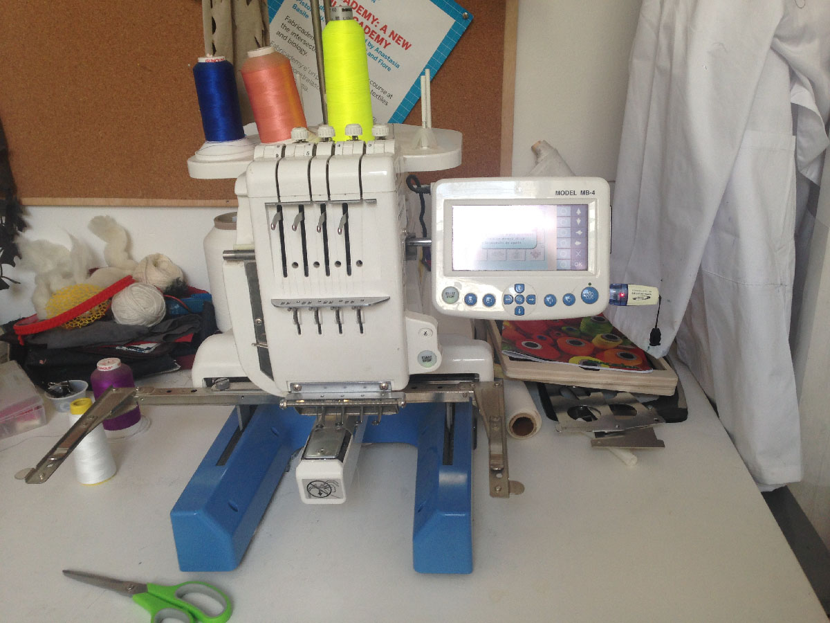
For sewing the conductive thread into felt I’m going to use Janome MB-4S Embroidery Machine (https://www.embroiderywithstyle.com/janome-embroidery-machine-review/). It appears thet we have it at the lab! Though I heard thet it’s glitching so I have to br prepared with special amount of patiency…
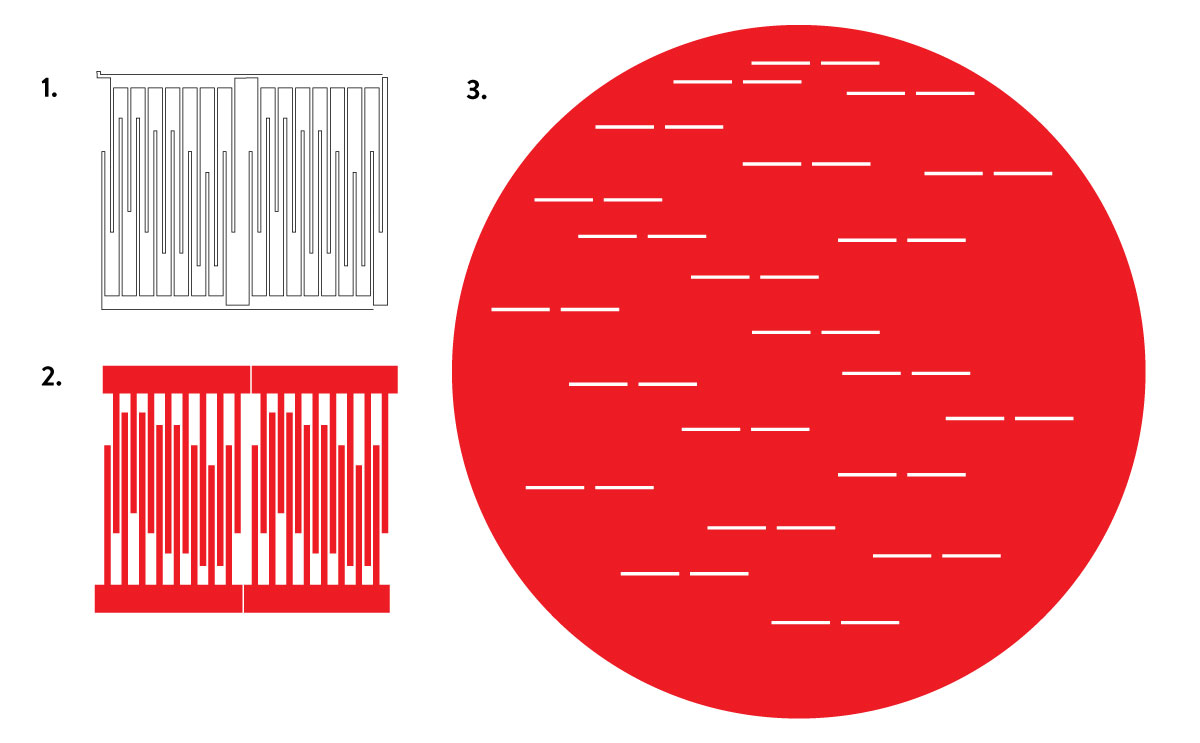
I’m going to create modules of “hairs” which will be placed together on the circular board. I’m designing a set of files related to each other. The plan will be the following:
- Use Janome to sew the conductive thread into pieces of felt.
- Lasercut this pieces into a stripes
- Stuff them into a lasercutted circle with holes for modules
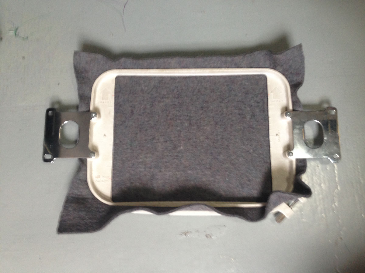
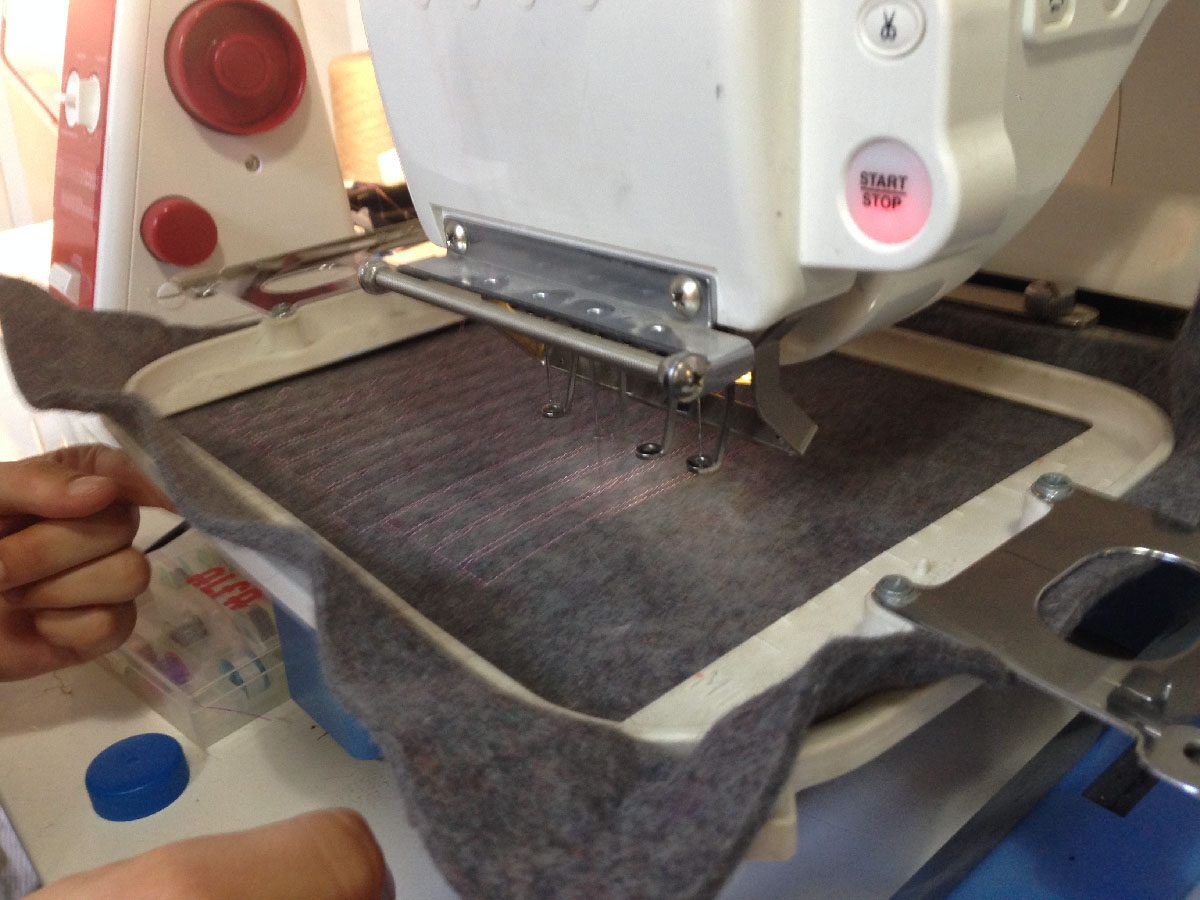
Sewing the thread into felt with Janome MB-4S
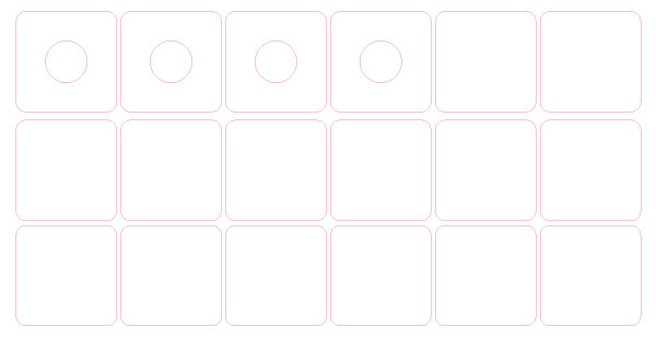
Embroidery machine has the specific bed-size which is 25x20 cm. I calculated that I can put four modules of the “hairs” in one design to get the most use from the material.
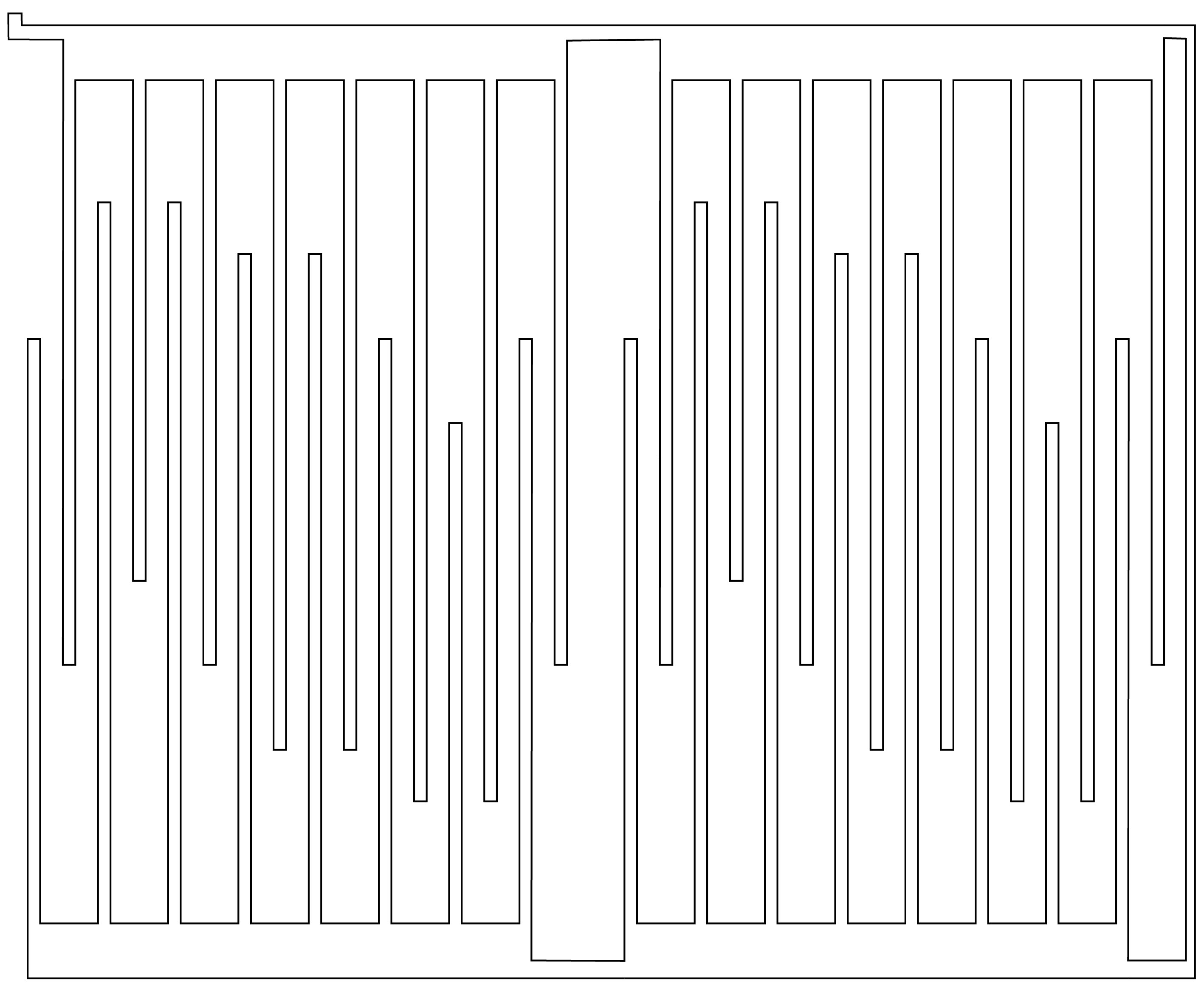
The design has to be prepared in jpg or png, it represents the way the conductive thread will be sewed into material. Even though I’m going to create four modules the design ofallof them should be connected as one line.
Lasercuttingthe felt
Felt is very good to cut on the laser, just (when is natural) stinks hellish like burned hair! It’s good to leave it after cutting fora night outside.
Before sweing with Janome I’ve made a test of the size of the holes through wich I’m going to pull felty strpes.
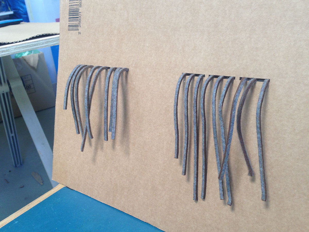
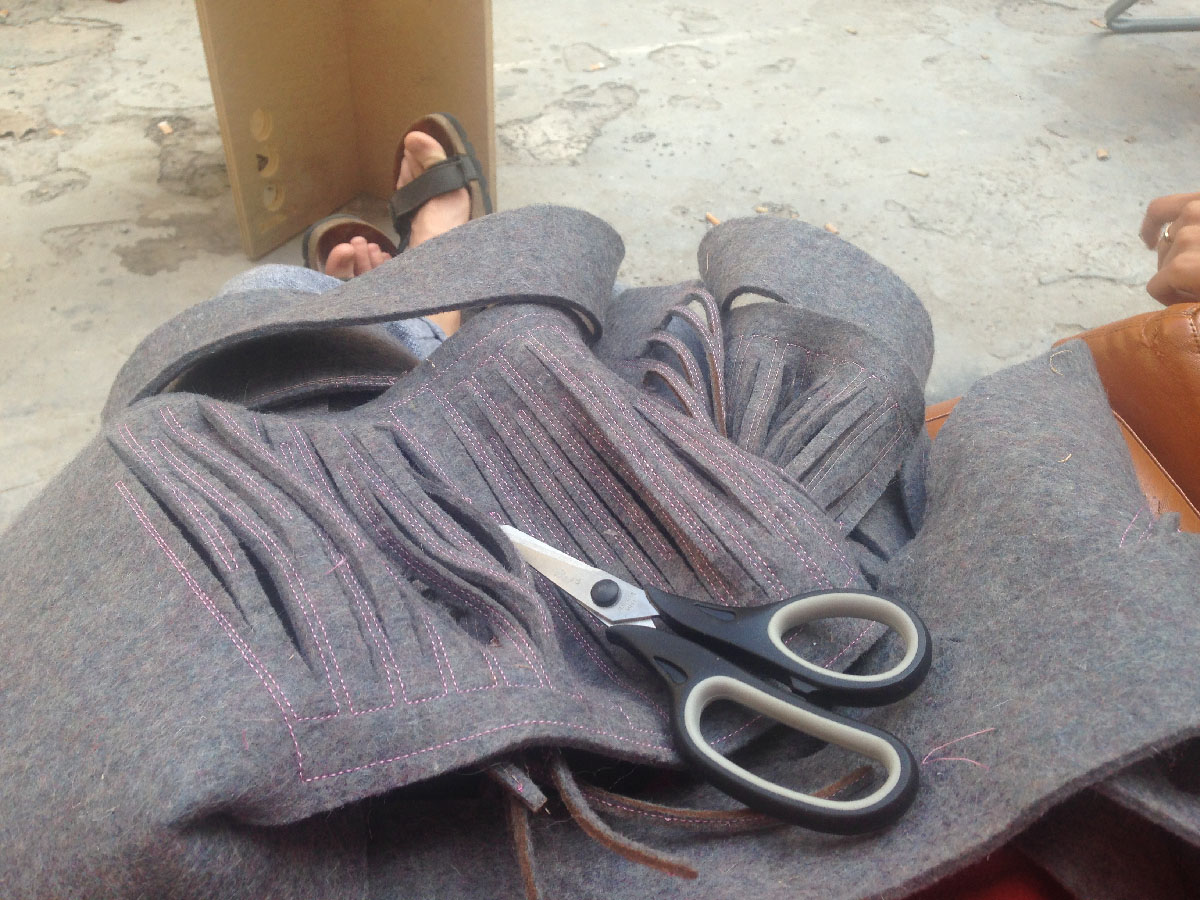
Now when I have the pieces with linesof thread comes the moment of the truth if the designs will match. Of course they were matching on the computer but in reality it’snot so easy! It appeared that felt got a bit stretched on the bed of the Janome machine and there is a mismatch. I’m cutting on laser some of the pieces and for the rest I’mdeciding to use cutter + sharp scisors.
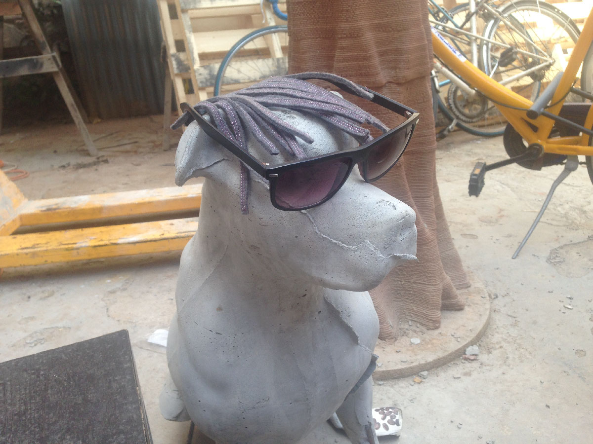
I’m spending a nice houron the yard of the fablab with my friend dog.
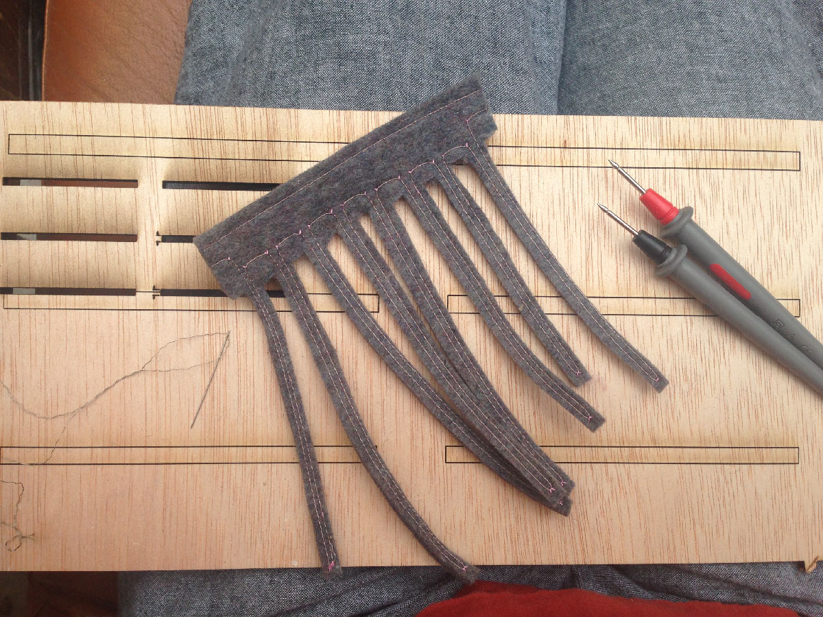
I’m checking the conductiveness with a multimeter. If there is a broken line I’m reparing it by sewing in a pieceof conductive thread. At the end Ihave 22 modules ready!
Now I’m going to create the circle with holes. First stepis to make a composite fromfelt and a pieceof 3mm plywood. For doing that I’m using PVA water based adhesive for wood.
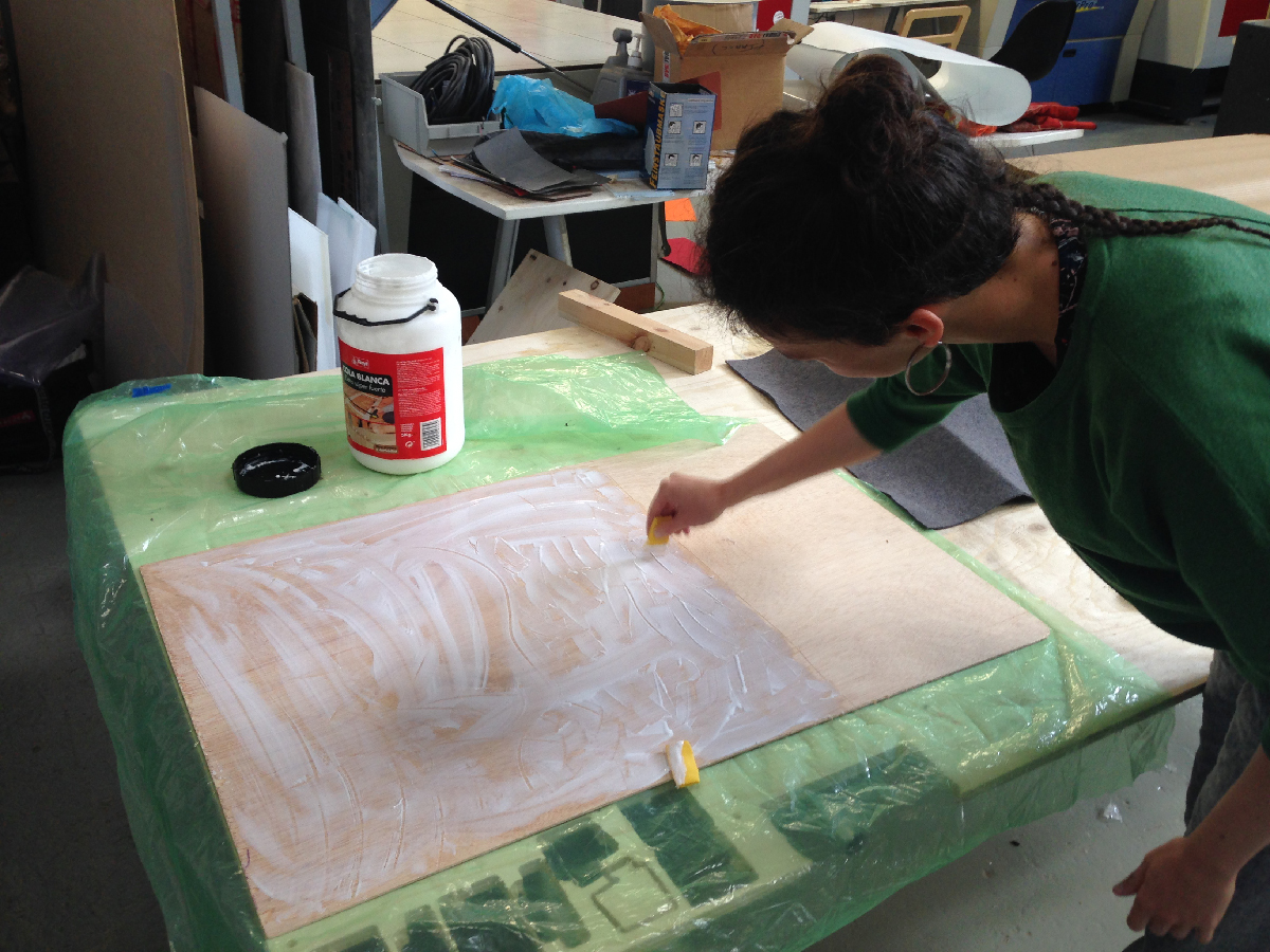
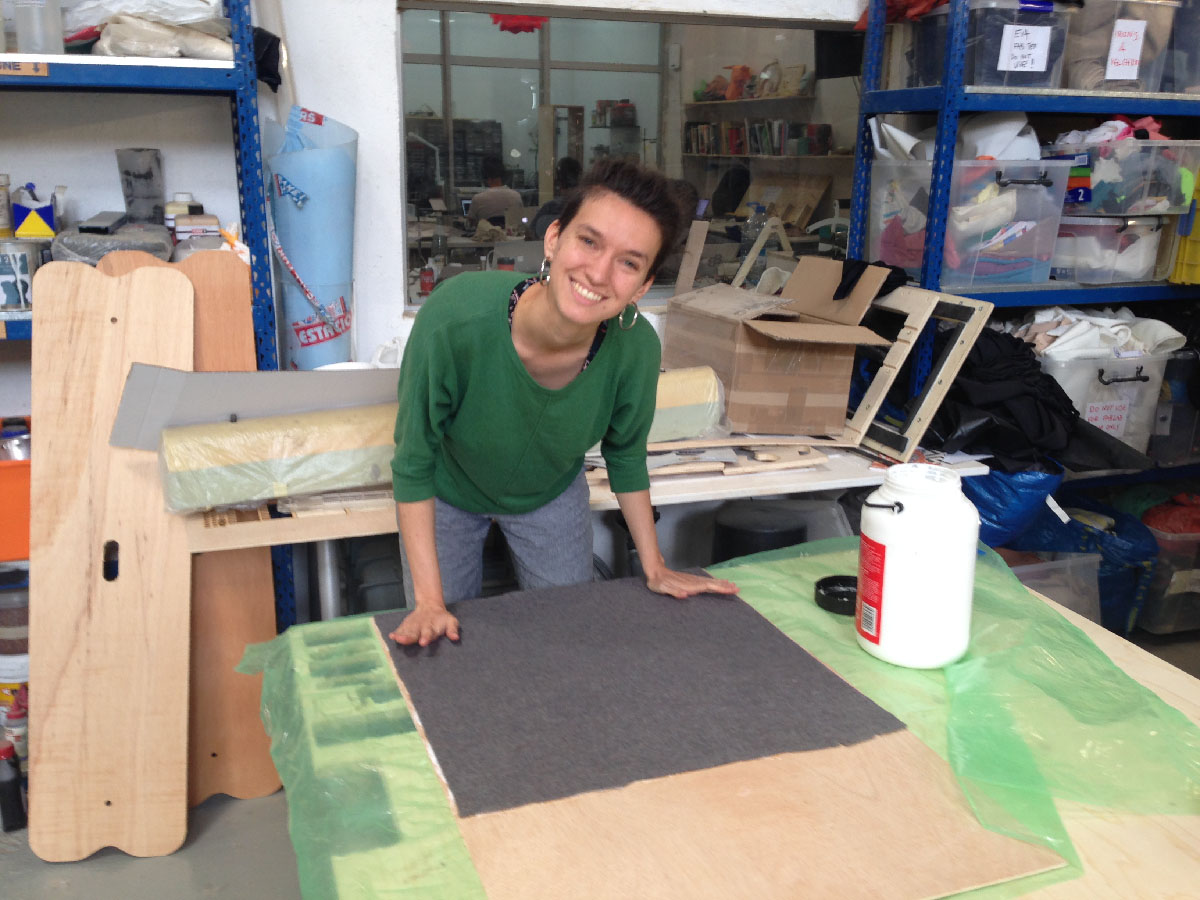
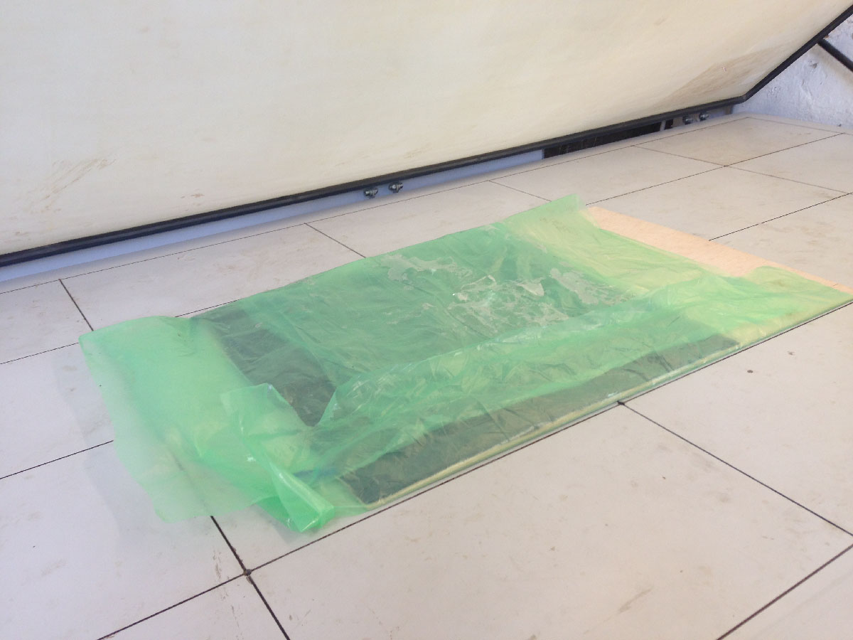
At the end I’m putting the composite forat least two hours into the Vacuum Table.
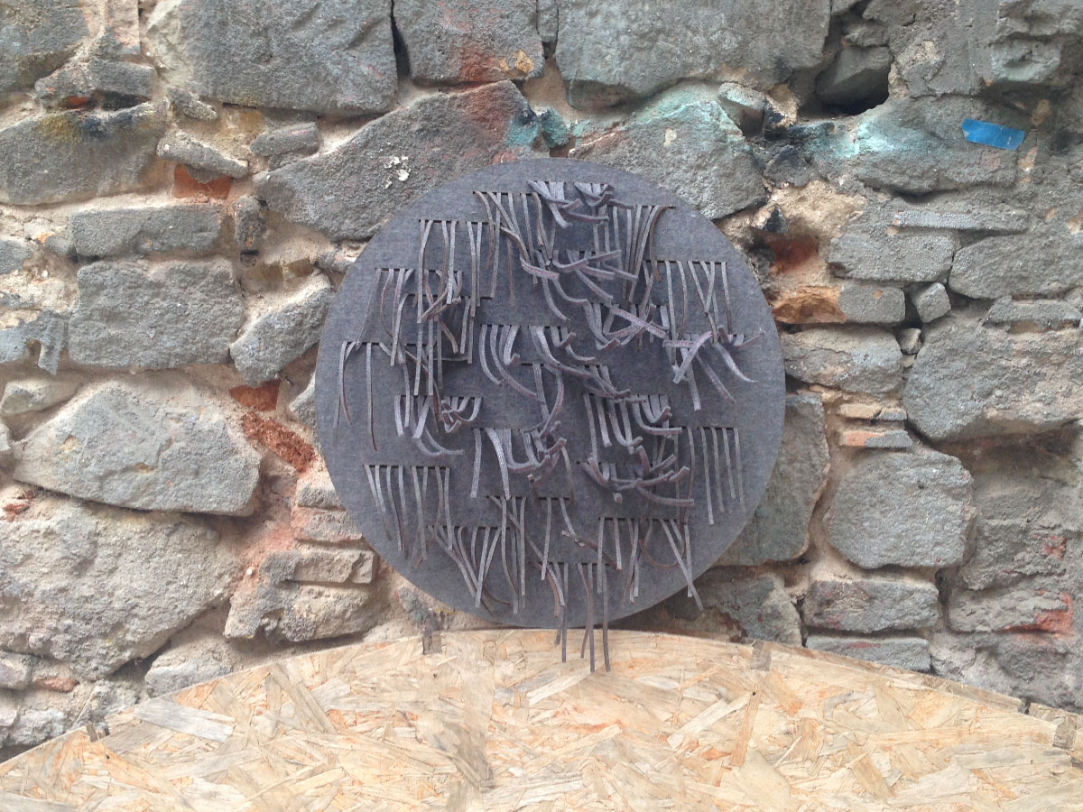
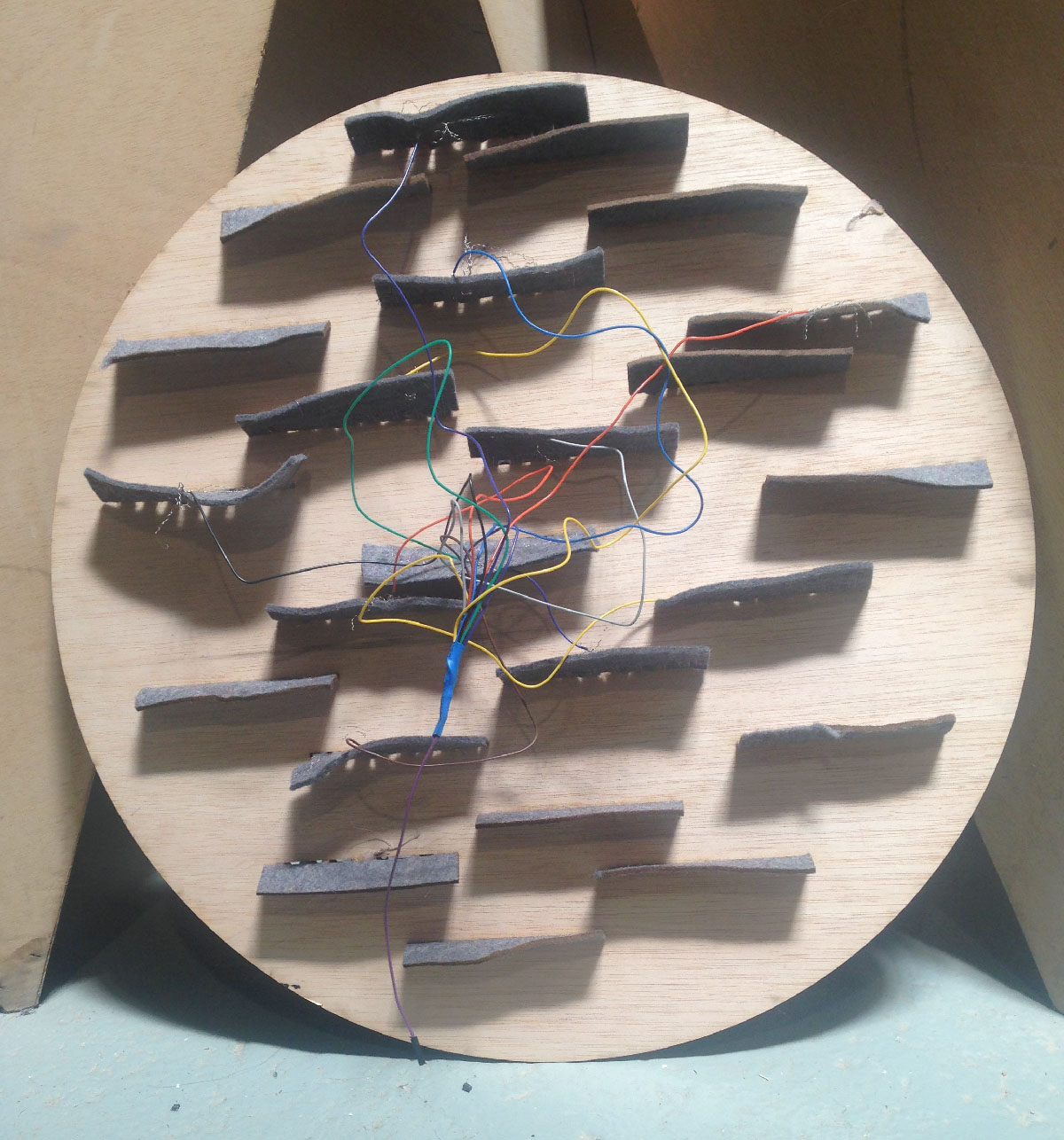
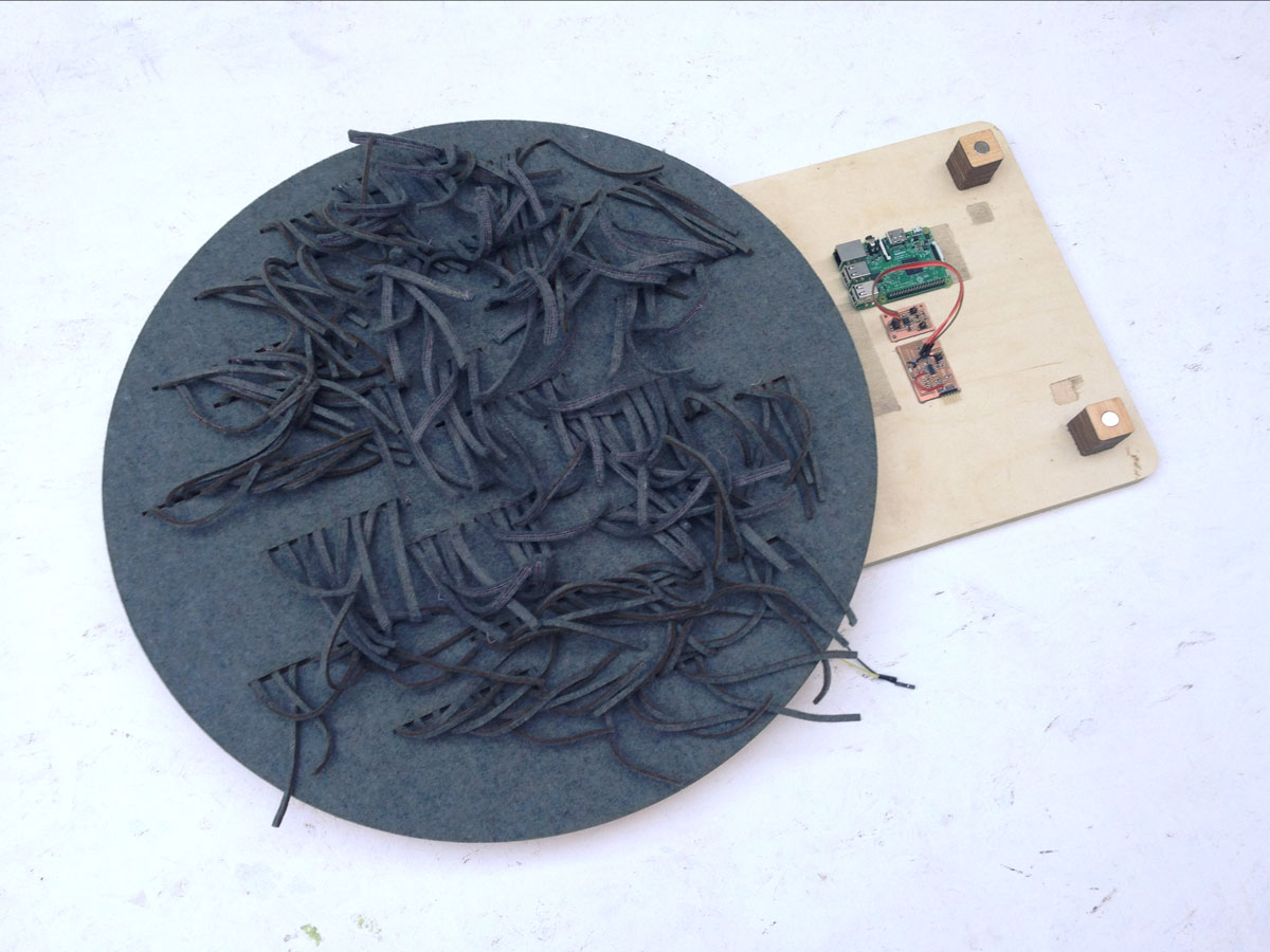
At the end ofthe day I’m pulling the stripes through the holes and the frontpart of the sensor can be called ready!
Next thing I’m doing is wiring everything together. I’m sweing the endings of wires with the conductive thread to each module. Than I’m connecting the wires into one which will go into sensing pin.
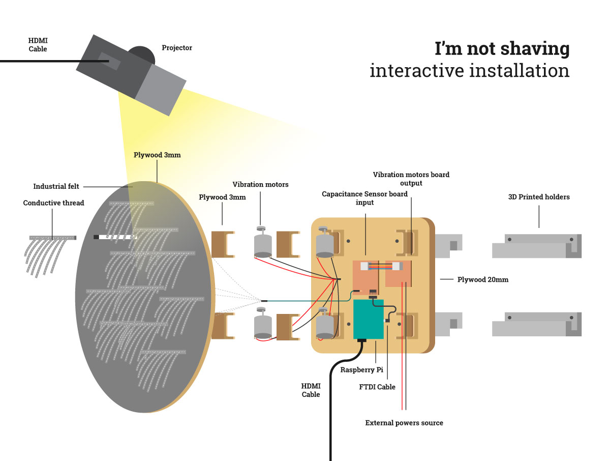
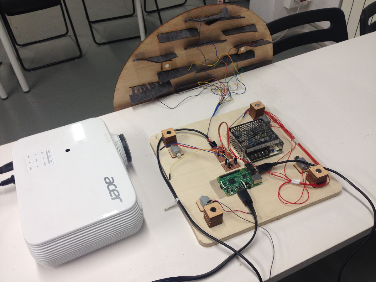
Back-board
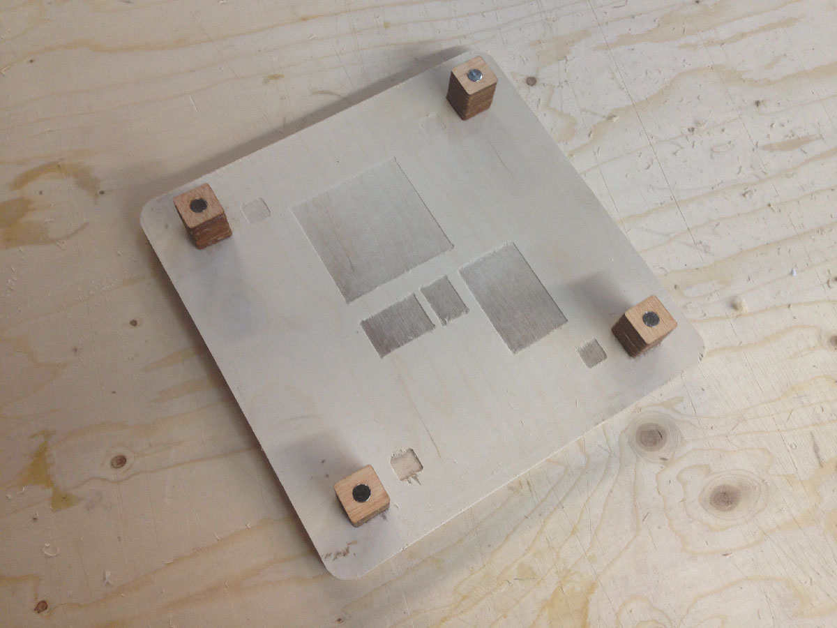
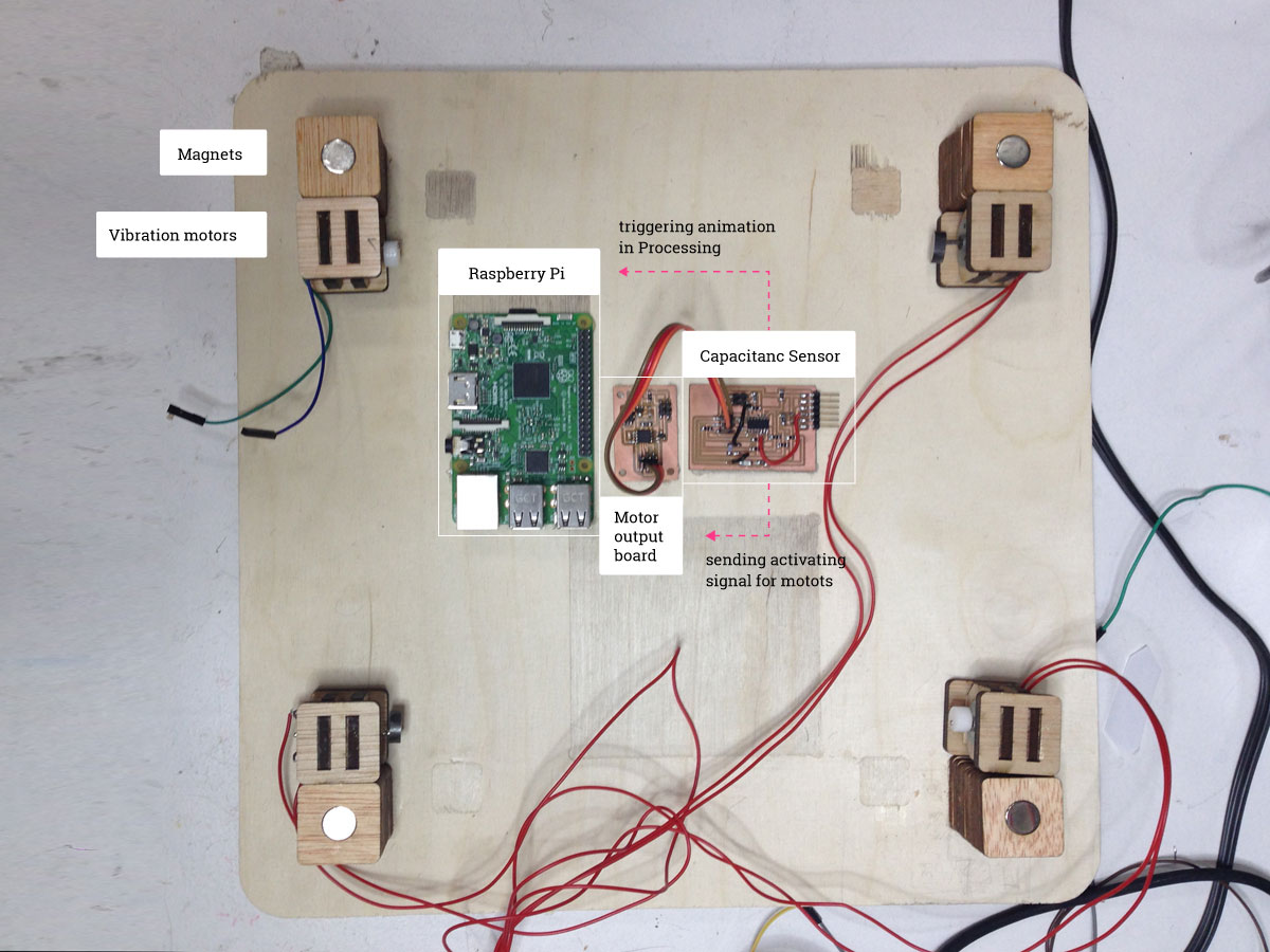
On the back-board I will place all the electronics: two PCBs, Raspberry Pi, battery. In case of battery I’m making a place for it now but probably make it work while working on next iteration of the project. For now I will power the motors through a cable with power adapter.
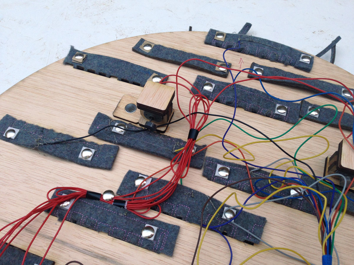
The board will also have a snapping mechanism based on magnets, and a place for four vibration motors. I’m going to build the holders for the motors based on press-fit soultion.
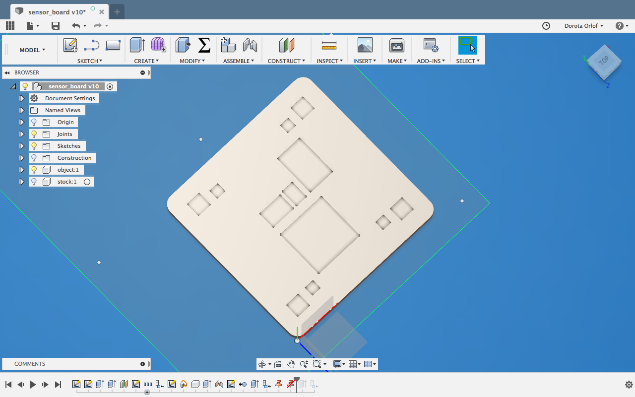
I’m designing the board in Fusion 360, using the skills that I’ve gained during Computer-Controlled Machining week.
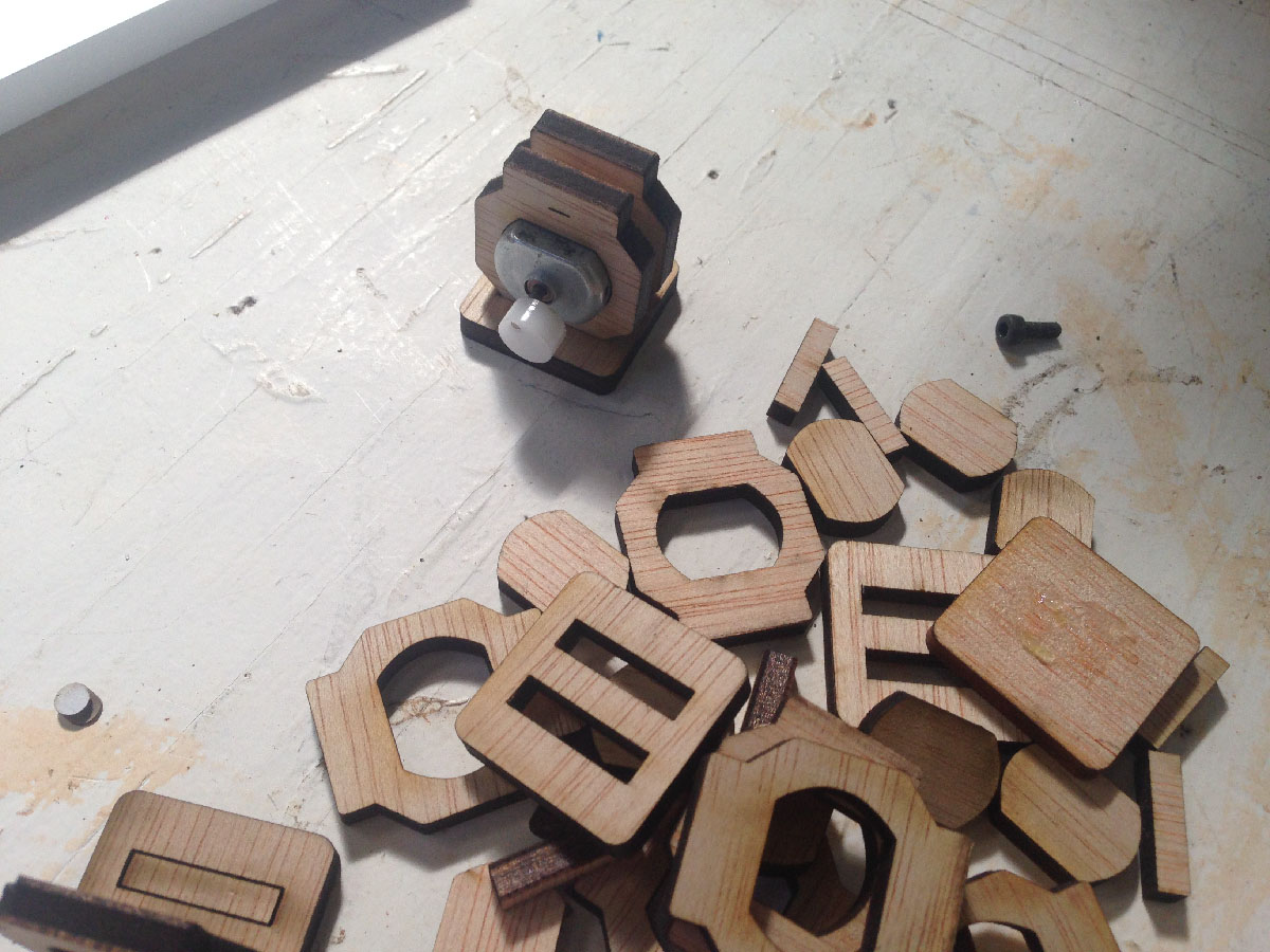
By using laser-cutter I’m cutting out magnet holders, and units from which I will build a support structure.
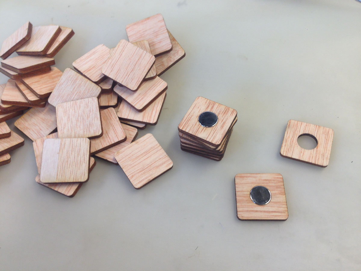
I’m milling the back-board with marks for elements to assemble. In that point I’m also building the “magnet towers”, by gluing the pieces together with a wood-glue.
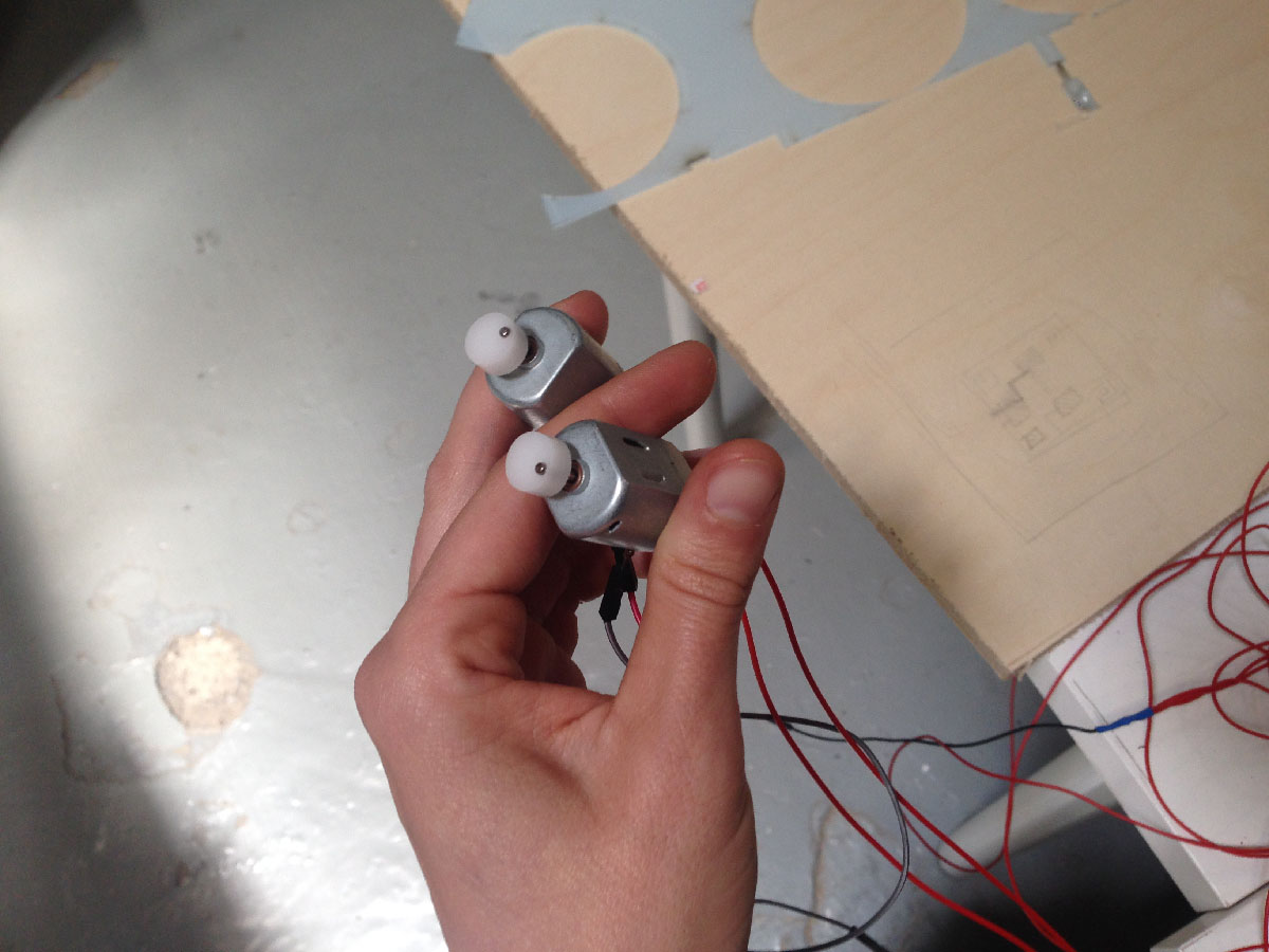
Since two of my motors donot have “caps” which are creating the vibrating movemen, I’m creating them from thick acrylics.
I’m assembling magnet-holders from lasercutted pieces.
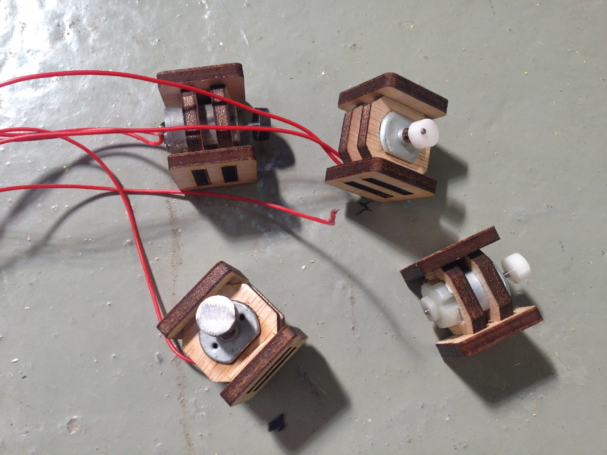
And fixing them on the board.
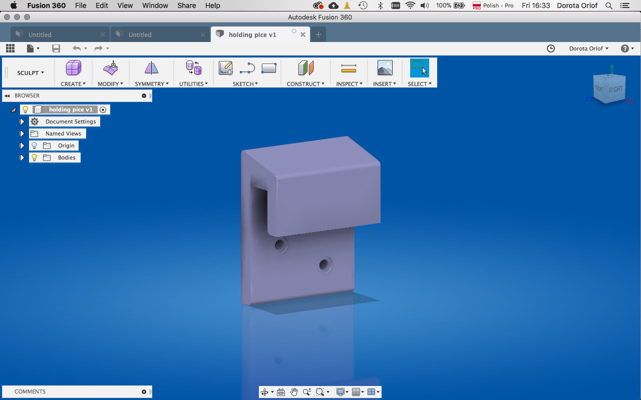
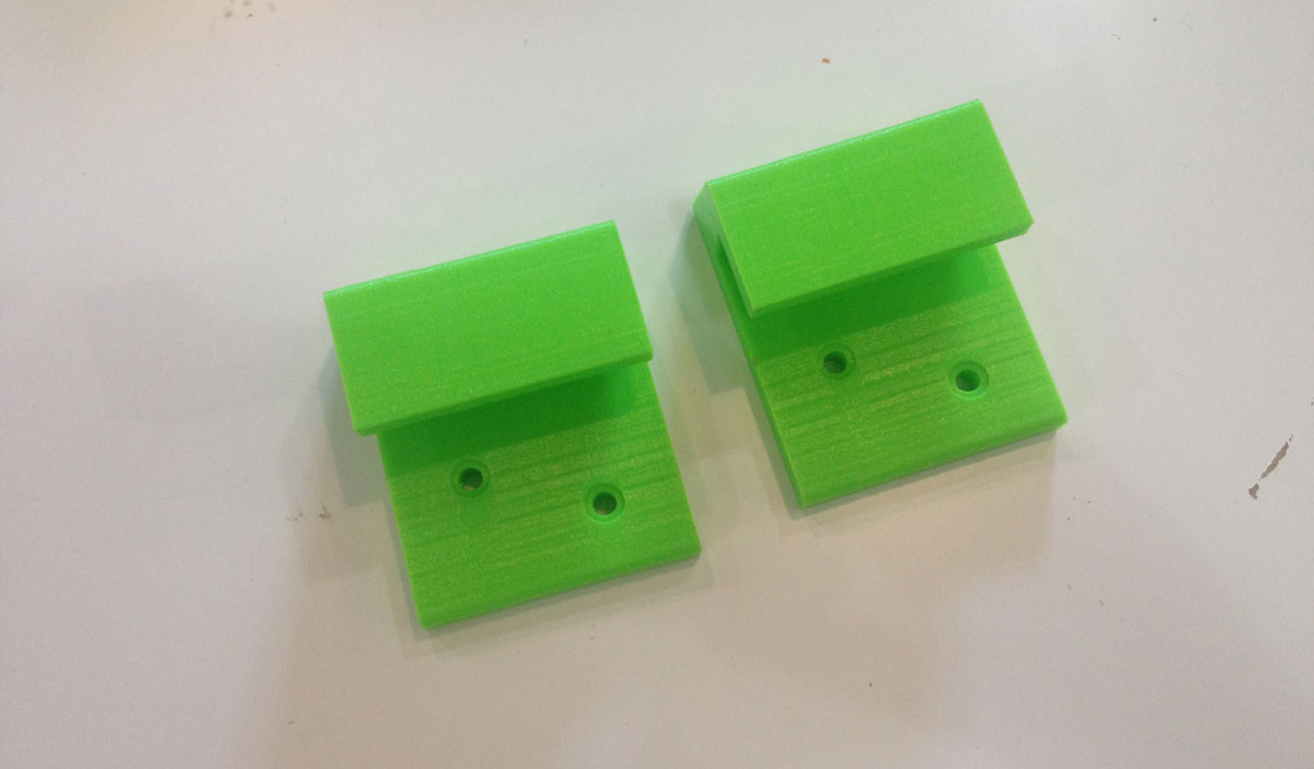
Holders for the back-boad
In Fusion 360 I’ve designed holding system for fixing the board on the wall. There are two holders which are going to be screwed to the wall. The back-board can be easily slide in inbetween them from the side.

Electronics
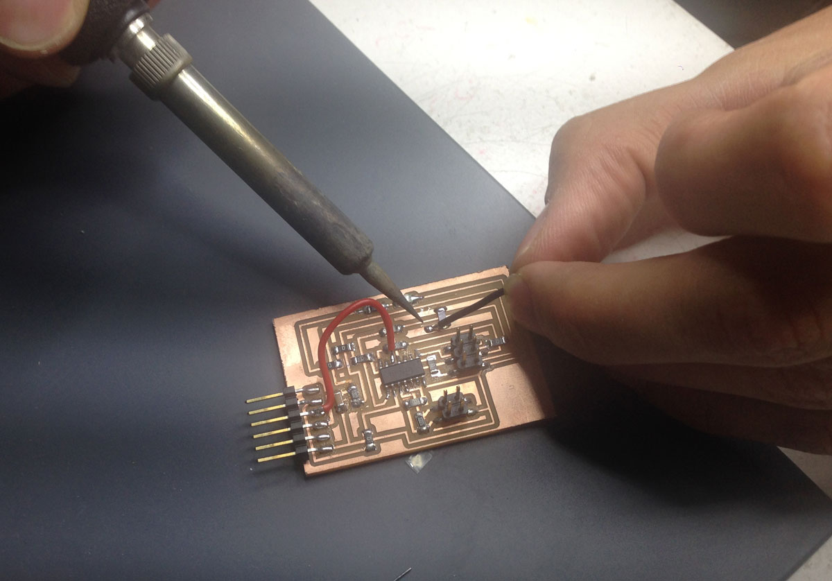
Since my capacitance sensor board (manufactured in Input Devices week) was behaving very unstabile (the sensed values were jumping sometimes in very hectic way) I’ve got recommended to add an extra 1uF capacitor. Since the time is running very quickly I’m deciding to solder an extra jumper cable instead milling board once more.
I’m going to connect four vibration motors to the board that I’ve created during Output Devices week) On my board I’ve left a place for the battery to power the motors, but it appeared that they are all working with 5Volts from FTDI cable! That’s coolsince the sensor will be lighter without the battery.
The flow will be as follows:
Sensor will send a signal through serial communication, this will activate the Processing animation running on RaspberryPi as well as the vibration motors.
Assemblage
All together the sensor is assembled from two parts.
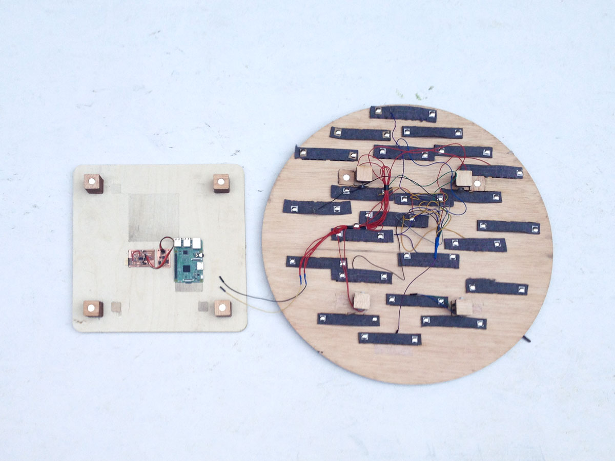
I’ve fixed the floating felt pieces with pins - they have perfect length for the thickness of a board.
Assemblage with all the cabling. In this case I’ve put the battery as a placeholder (it appeared later that it’s not necessary).
Programming
I’m going to re-do the Arduino code for Capacitance Sensor that I’ve written during the Networking and Communication week
Kris gave me tipps how to get more stabile results. To reach that I’m going to use long capacitiveSensor(byte samples) method. Detailed description one can find on Capacitive Sensing Library page by Arduino.
#include <SoftwareSerial.h>
#include <CapacitiveSensor.h>

#define NUM_SAMPLES 30
#define THRESHOLD 5000

SoftwareSerial myComCat(8, 4);
SoftwareSerial myComDog(5, 6);

CapacitiveSensor cs_2_3 = CapacitiveSensor(2, 3);

unsigned long average = 0;
unsigned long threshold = THRESHOLD;
unsigned long samples[NUM_SAMPLES];
int currSample = 0;
int maxSamples = NUM_SAMPLES;

void setup() {
  myComCat.begin(9600);
  myComDog.begin(9600);
}

void loop(){
  myComCat.listen();
  while (myComCat.available() > 0) {
    char inByte = myComCat.read();
    myComDog.write(inByte);
  }

  delay(100);

  unsigned long reading = cs_2_3.capacitiveSensor(30);

  if(currSample < maxSamples){
In the beginning we have to read the first NUM_SAMPLES samples since the array is empty.
    samples[currSample] = reading;
    currSample++;

    myComCat.println("sampling...");
  }else{
When we are done reading in the NUM_SAMPLES readings we have an array we can use for averaging. We have to shift all readings of an array. We have to drop the first one and add one on top so that we still have only NUM_SAMPLES readings.
Remove one sample from the beginning and add one sample at the end of the array:
    for(int i = 0; i < maxSamples; i++){
      if(i < maxSamples - 1){
        samples[i] = samples[i+1];
      }else{
        samples[i] = reading;
      }
    }

    unsigned long sum = 0;
    for(int i = 0; i < maxSamples; i++){
      sum += samples[i];
    }

    unsigned long numSamples = NUM_SAMPLES;
    average = sum / numSamples;
    myComCat.print("sum: ");
    myComCat.print(sum);
    myComCat.print("\t");
    myComCat.print("average: ");
    myComCat.print(average);
    myComCat.print("\t");
    myComCat.print("reading: ");
    myComCat.println(reading);

    if (reading > average + threshold) {
      myComCat.println("Fingers move!");
      myComDog.write('1');
    }
  }
}
I’m connecting the furry sensor to the board and testing if the data are being red according to the plan.
For output board I’m using the same code that I’ve used for the Networking and Communication Assignment.
#include <SoftwareSerial.h>

const int vibPin =  1;
unsigned long previousMillis = 0;
unsigned long interval = 2000;
Since we use the port for listening only (on RX, which is 0) It is ok, that the TX pin is the same as vibPin.
SoftwareSerial inputPort(0, 1);

void setup() {
  pinMode(vibPin, OUTPUT);
  inputPort.begin(9600);
  previousMillis = millis();
}

void loop() {
Move the DC Motor
  unsigned long currentMillis = millis();
  unsigned long timePassed = currentMillis - previousMillis;
  if (timePassed > interval) {
    digitalWrite(vibPin, LOW);
  }else{
    digitalWrite(vibPin, HIGH);
  }

  while (inputPort.available() > 0) {
    char inByte = inputPort.read();
Addressing: When we receive 1, we spin the motor
    if (inByte == '1') {
      previousMillis = currentMillis;
    }
  }
}
From the other end I’m going to modify the Processing code that I’ve created during the Interface and application programming week. This time I’m going to run an animation by displaying four pngs one after another.
import processing.serial.*; //import the Serial library

Serial doraPort;  //the Serial port object
String val;

Animation animation1, animation2;

float xpos;
float ypos;
float drag = 30.0;

boolean firstContact = false;

void setup() {
  fullScreen();
  background(0);
  frameRate(24);

  animation1 = new Animation("anim_", 1);
  animation2 = new Animation("anim_", 4);
  ypos = height * 0.25;

  doraPort = new Serial(this, Serial.list()[1], 9600);
  doraPort.bufferUntil('\n');
}

void draw() {
animation2.display(0, 0);
}

void serialEvent( Serial myPort ) {
put the incoming data into a String - the ‘\n’ is our end delimiter indicating the end of a complete packet
val = myPort.readStringUntil('\n');
make sure our data isn’t empty before continuing
if (val != null) {
trim whitespace and formatting characters (like carriage return)
    val = trim(val);
    println(val);


    }else if(val.equals("high")){
      animation2.display(0, 0);
    } else {

    animation1.display(0, 0);
  }

  }
  class Animation {
  PImage[] images;
  int imageCount;
  int frame;

  Animation(String imagePrefix, int count) {
    imageCount = count;
    images = new PImage[imageCount];

    for (int i = 0; i < imageCount; i++) {
Use nf() to number format ‘i’ into four digits
      String filename = imagePrefix + nf(i, 2) + ".gif";
      images[i] = loadImage(filename);
    }
  }

  void display(float xpos, float ypos) {
    frame = (frame+1) % imageCount;
    image(images[frame], xpos, ypos);
    delay(100);
  }

  int getWidth() {
    return images[0].width;
  }
}
Projection mapping
I’m transfering the files to RaspberryPi and testing the animation. It’s finally waving to me.
After setting up everything in the proper settings the animated hand is ready to be tickled!
Bill of Materials
- Sensor board:
Resistor 10MegOhm / Digi-Key / 0.1 euro
Resistor 10KilOhm / Digi-Key / 0.1 euro
2x2 pin SMD Header / Digi-Key / 0.60 euro
2x3 pin ISP SMD Header / Digi-Key / 0.66 euro
6 pin SMD header / Digi-Key / 0.60 euro
Capacitor 1uf / Digi-Key / 0.12 euro
AtTiny 84 / Digi-Key / 2 euro
Led / Digi-Key / 0.13 euro
Resistor 499Ohm / Digi-Key / 0.1euro
Resistor 0 x 8 / Digi-Key / 0.1euro each
- Output board:
2x2 pin SMD Header x2 / Digi-Key / 0.60 euro each
Mosfet N / Digi-Key / 0.34 euro
2x3 pin SMD Header x2 / Digi-Key / 0.66 euro each
AtTiny 45 / Digi-Key / 1.23 euro
Voltage regulator 5V / Digi-Key / 0.34 euro
Capacitor 1uf / Digi-Key / 0.12 euro
Resistor 10k / Digi-Key / 0.1 euro
Resistor 0 x2 / Digi-Key / 0.1 euro each
- 1x2m sheet of industrial felt / bought in the local felt store / 23 euro /
- conductive thread / from FabLab Barcelona, ordered online / 42 euro
- piece of plywood 5mm and 1,5cm / from FabLab Barcelona,orderedin wood store / ca 15 euro
- two 3D printed holders / from FabLab Barcelona /
- three vibration motors / from FabLab Barcelona, ordered online / each 5.70 euro
- rented Projector / from FabLab Barcelona, there is one that I can use
- FTDI cable / from FabLab Barcelona, ordered online / 17 euro
- Raspberry Pi / bought online / 39 euro

This work is licensed under a Creative Commons Attribution 4.0 International License.
Files made during this assignment:
Circular board dxf
Circular board ai
Hairy unit / laser dxf
Hairy unit / laser ai
Hairy unit / png for janome
Magnet holders ai
Magnet holders dxf
Motor holders ai
Motor holders dxf
3D printed holder / f3d
3D printed holder / stl
Code Capacitance Sensor
Code Motor Output
Code Processing