Week 4: PCB milling test (group assignment)
This week we followed the electronics production class (see video here)
This week we had group and individual assignments. This page is about the group assignment that we did for testing the PCB production. In this process we will be milling a FR1 (phenolic paper) board using the CNC milling machine.
Generating .RML files
The first step is to make a conversion of our traces design from .PNG files in .RML files supported by the Roland SRM-20 mill.
We will convert two files, the fist one for “traces” with the intent of only cutting only the thin copper layer from the top of the board. The second file for “outline” with the intent of cutting completely through the board to separate out circuit from the leftover board.
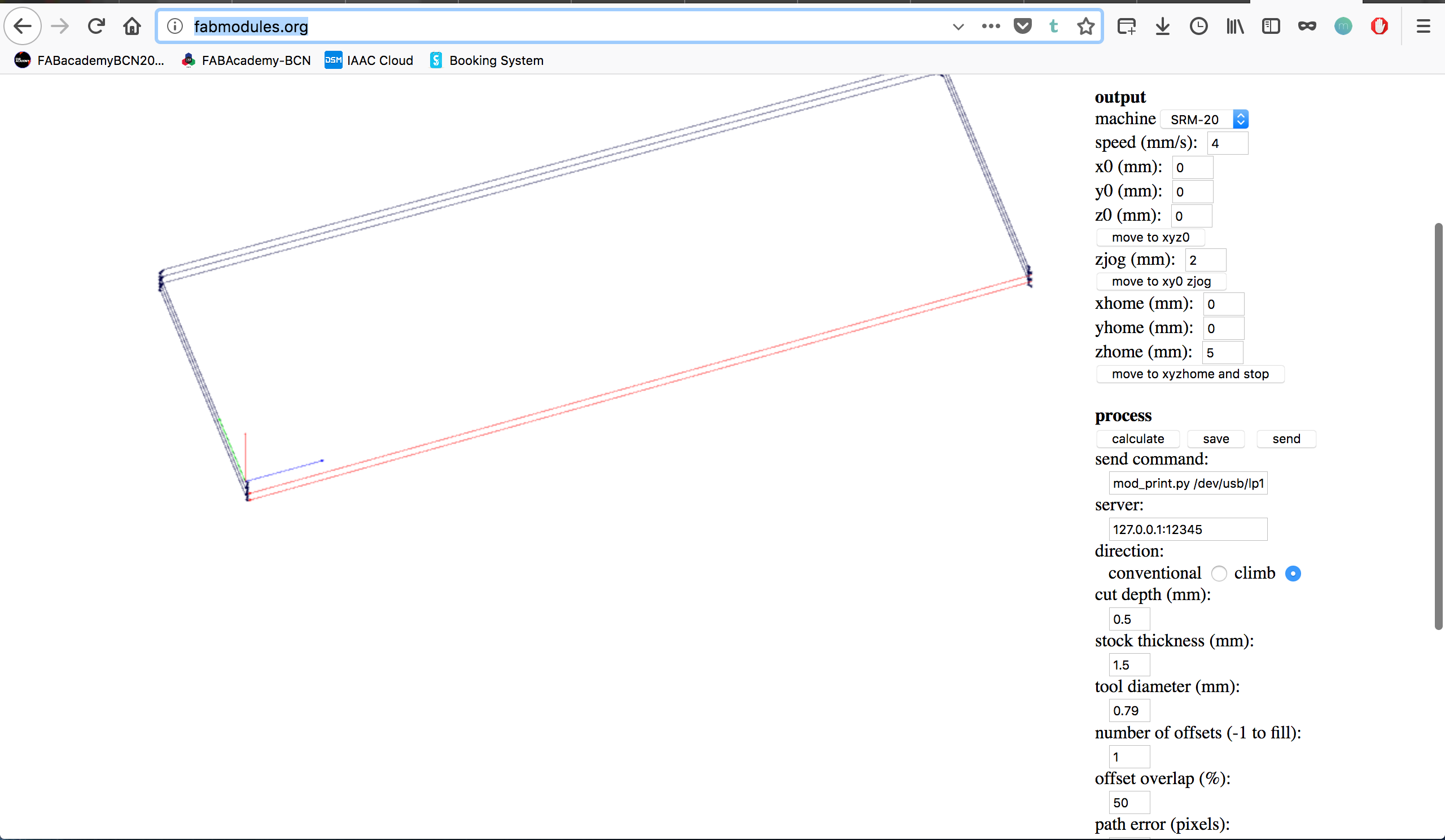
For doing this we used http://fabmodules.org/
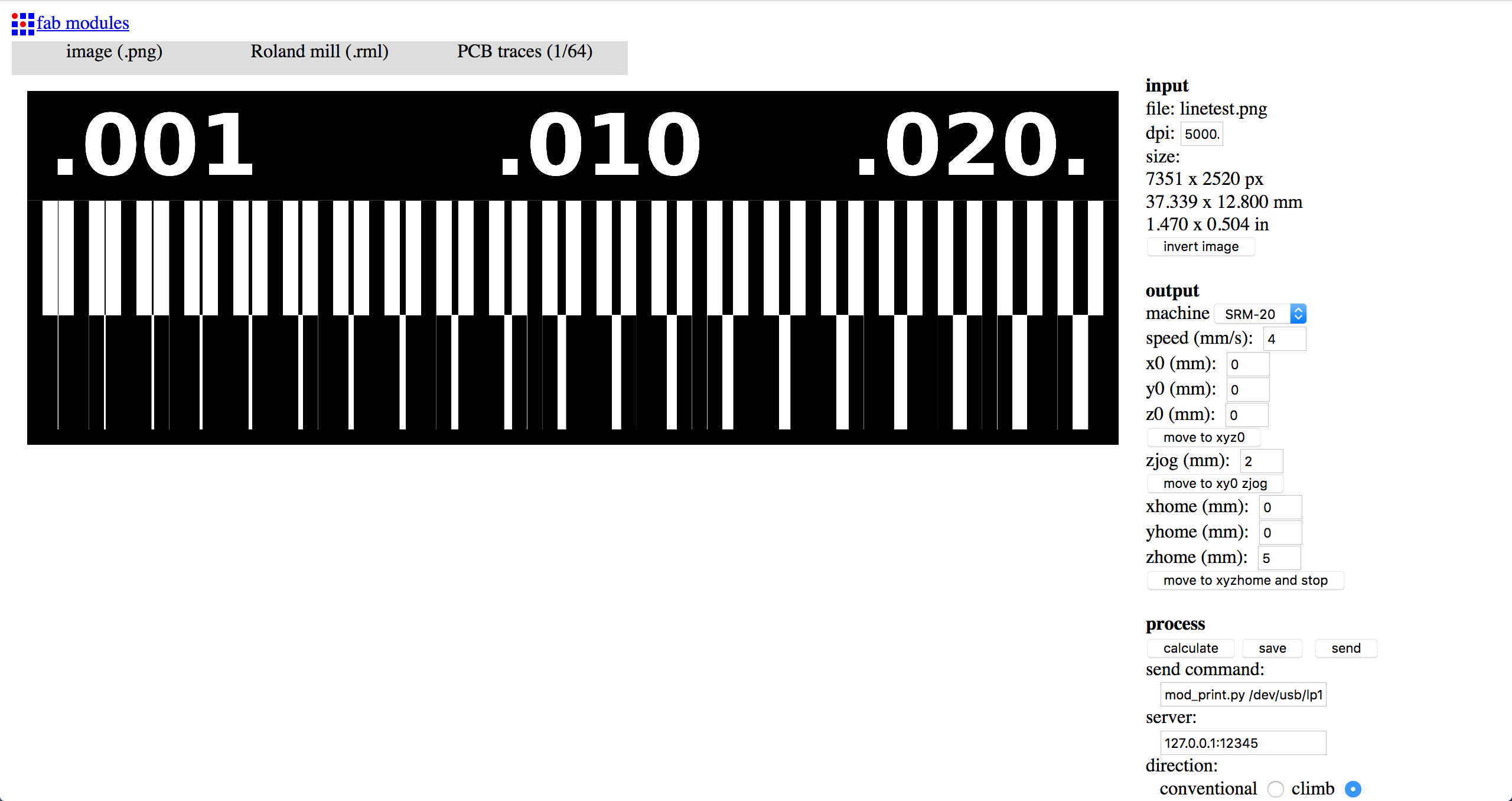
- Choose “Input Format”: Import the .png file
- Choose “Output Format”: Roland mill .rml
- Choose “Process”: PCB Traces (1/64) for the traces file.
Later we’ll repeat the process and choose instead “PCB Outline (1/32)” for the outline files.
For both processes we manually set some common parameters for our machine on the right menu:
In the “Output” section:
| Machine | xhome (mm) | yhome (mm) | zhome (mm) |
|---|---|---|---|
| SRM-20 | 0 | 0 | 5 |
The purpose of thise last settings is to make sure the machine moves back to a position with a positive value of “z” at the end of the process. If not, we risk to scratch the board when the cuting tool returns to the “home” position.
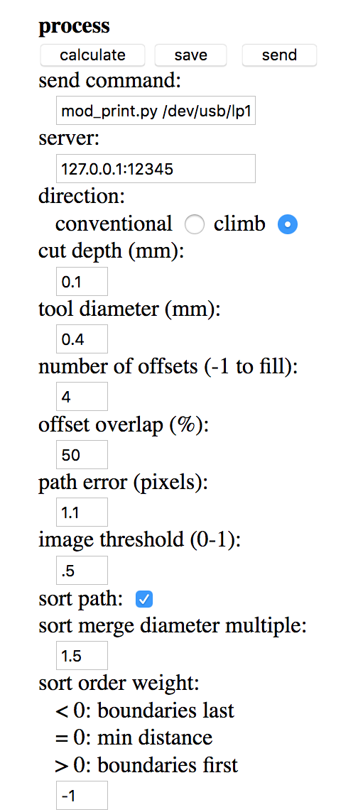
Other useful parameters for the traces files are in the “Process” section (default values should already be fine):
| cut depth (mm) | tool diameter (mm) | number of offsets |
|---|---|---|
| 0.1 | 0.4 | 4 |
Here “cut depth (mm)” corresponds to the thickness of the copper layer to cut. “tool diameter (mm)” corresponds to the 1/64 tool. “number of offsets” corresponds to the number of rounds the tool will do around each trace, if the value “-1” is selected the tool will completely clean the board from unnecessary leftovers, but it will take much more time to do so.
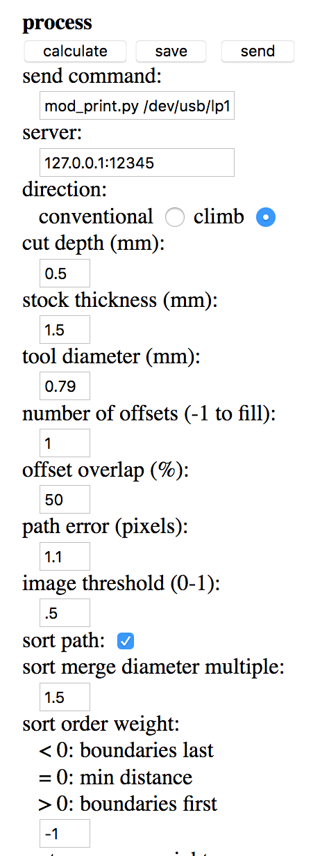
When we will repeat the process for the “PCB Outline (1/32)” the right menu section will be slightly different. In particular we can set:
| cut depth (mm) | stock thickness (mm) |
|---|---|
| 0.5 | 1.5 |
For this process the “cut depth (mm)” is much bigger because we want to cut through the entire board. The tool will cut 0.5mm on each pass, to reach the value of 1.5mm will therefore do 3 passes on the outline.
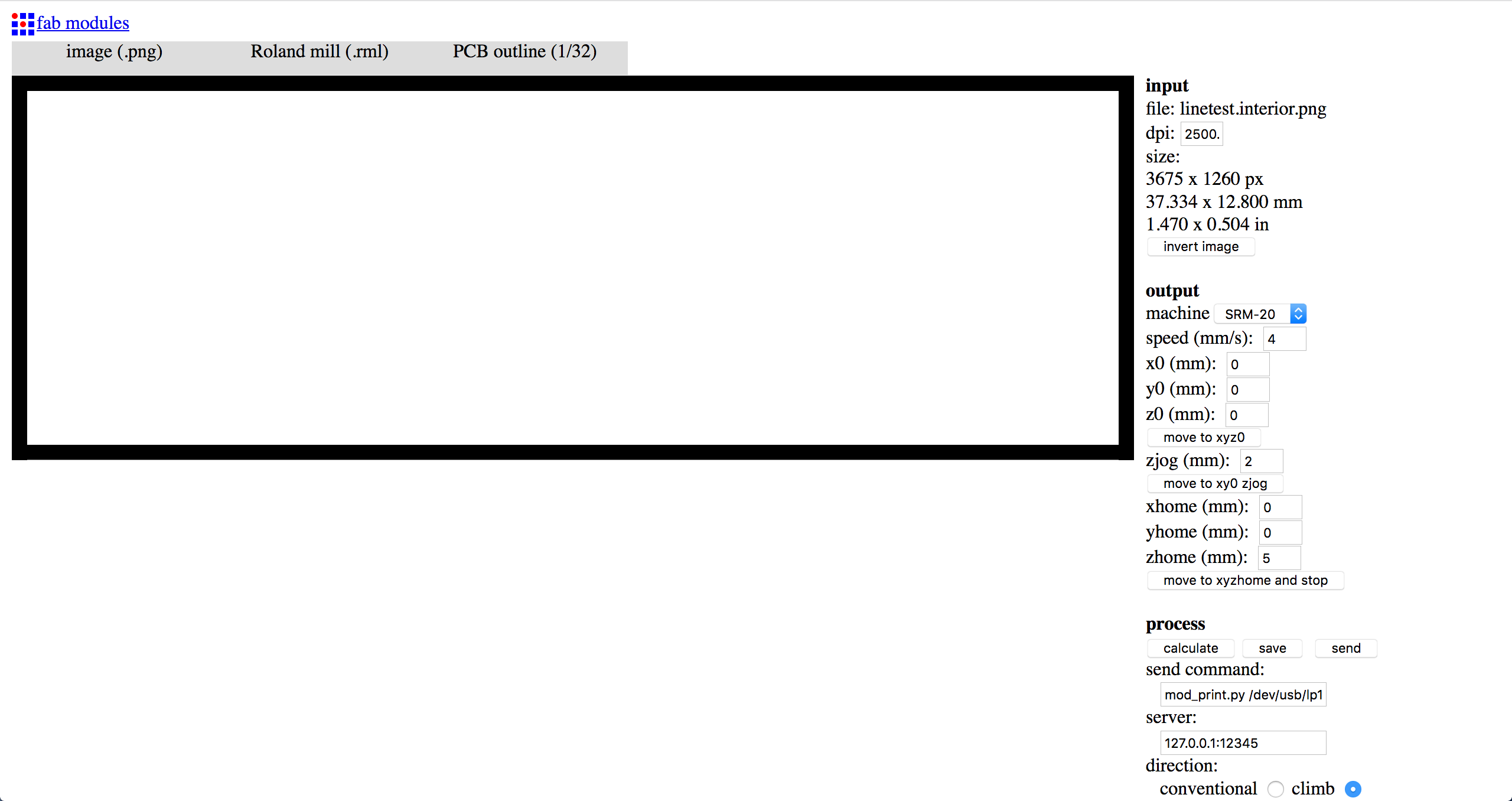
In both cases press “Calculate” to generate the tool path.
At this point will be possible to check it in the 3D generated visualization of the path (blue lines are cuts, red line are movements over the board).
After checking the path we can clik “save”.
Download traces source file (.rml)
Download outline source file (.rml)
Update: Note that this way of generating .rml file became obsolete.
See the week6 assignment on how to generate .rml files with mods.
Setting up the board and tools
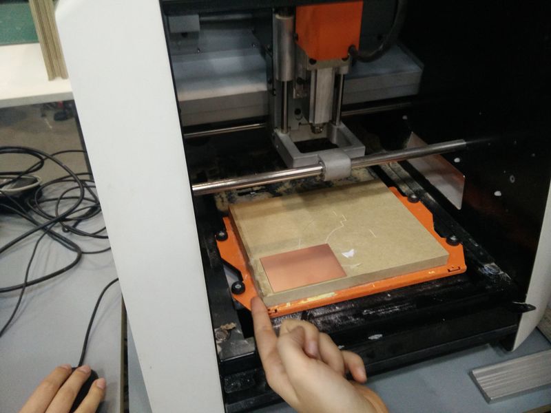
We will place the new board in the machine on a “sacrificial layer” that is a support surface that we don’t care if get cut when we go through our board.
The PCB boards that we are using have the following sizes: | width (mm) | height (mm) | thickness (mm) | |:———–|:————|:—————| | 75.96 | 50.40 | 1.58 |
Especially when creating big boards or if we want to cut multiple ones from a single PCB is useful to keep these in mind.
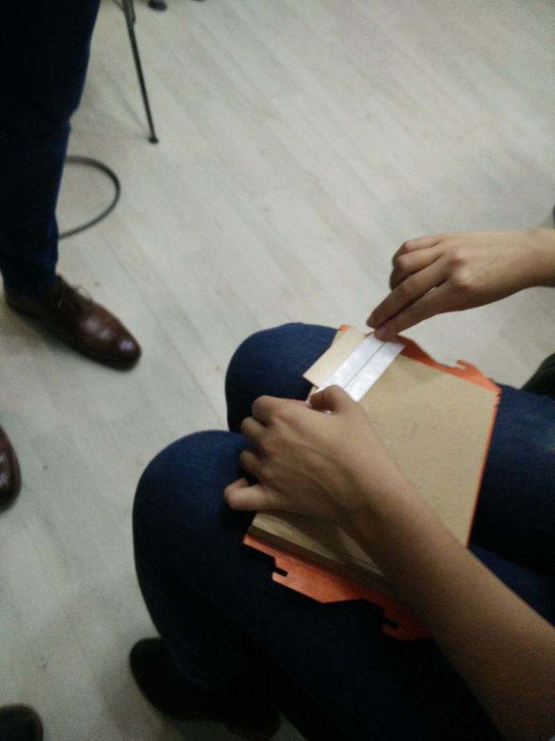
The board is attached on the sacrificial layer with a double sided tape. It is important for the success of the milling that all the surfaces are checked to be well clean and flat.
- Open the lid and remove the support with “sacrificial layer”. Clean it. Make sure there is no left over of tape.
- Check if board is flat by placing it over a ruler. If not, bend it slightly.
- Clean the board and put stripes of the double side tape on the back of the board. Make sure to do not overlap the stripes otherwise it would create a bump.
- Put the support back in the machine.
Go for the computer and run the Roland VPanel software.
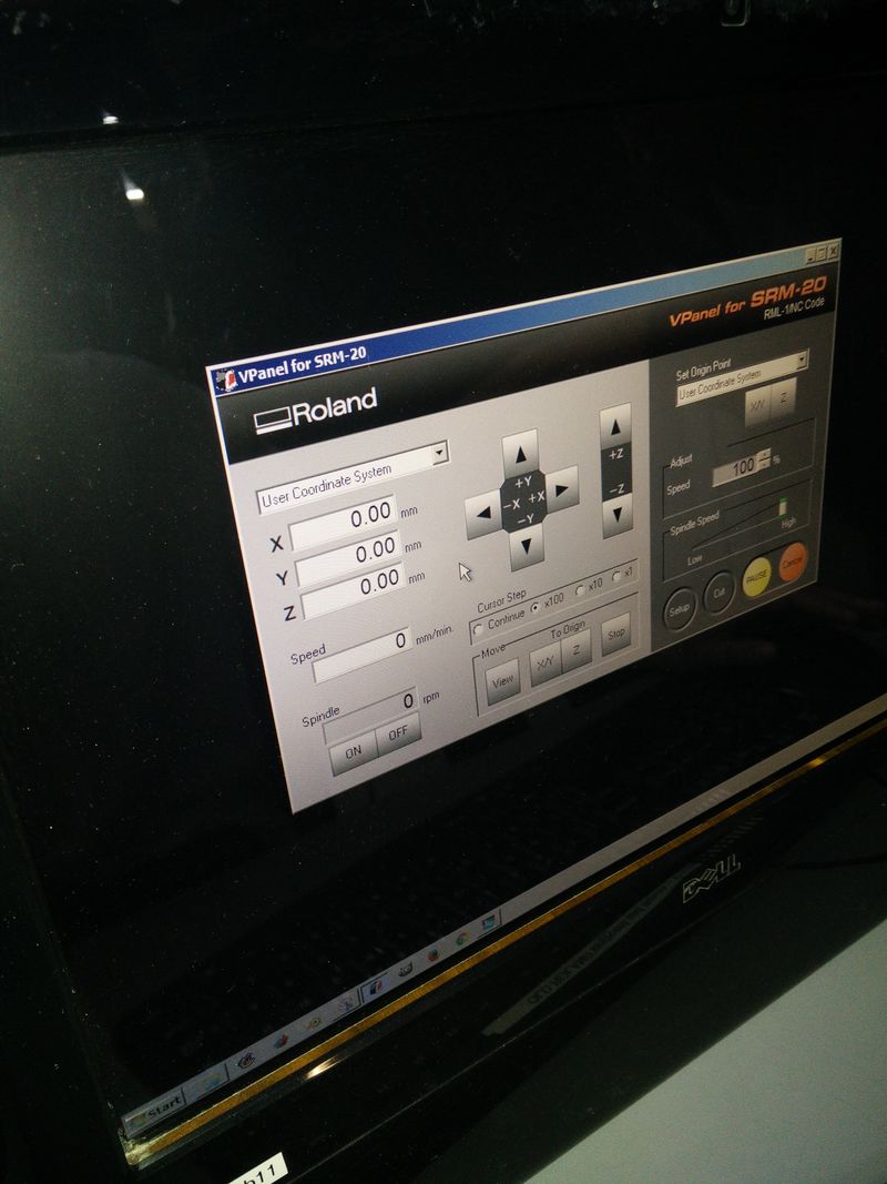
The main step we have to do before milling is to configure the “zero” or “origin” of the tool.
- From the VPanel software use the moving scale parameters and to adjust the position up in order to be able to insert the tool.
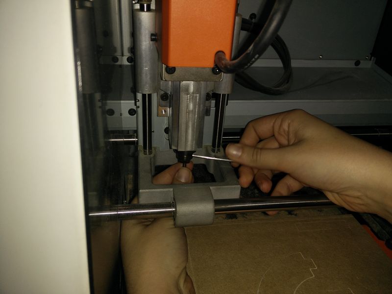
- We first put the cutting tool (1/64 for tracing and 1/32 for cutting) and screw it slightly further up.
- Place the “origin” for the X and Y coordinates first via the software: reach a corner of the board with a little margin and then click the “Set origin point” for XY button.
- To set the “origin” for the Z coordinate we just unscrew the tool and let it go down (gently by holding it) until it touches the board and then screw it back. After this step check that there is enough margin on the machine guides to go further down during the cutting. Click the “Set origin point” with the Z button
The milling process
Now the setup is completed and we will run the cutting process.
Before we start the tool “Spindle Speed” should be close to the “High” maximum value.
The tool movement “Adjust” / “Speed” should start slow (around 10%) and later we can manually increase up to 60/70%.
Moving the tool too fast increases the risk of breaking the tool head which is quite small and delicate.
- Load the file: Pressing the “Cut” button.
- “Delete All” the previous jobs and then click “Add” to import your file.
- Press the output button so that the process will start.
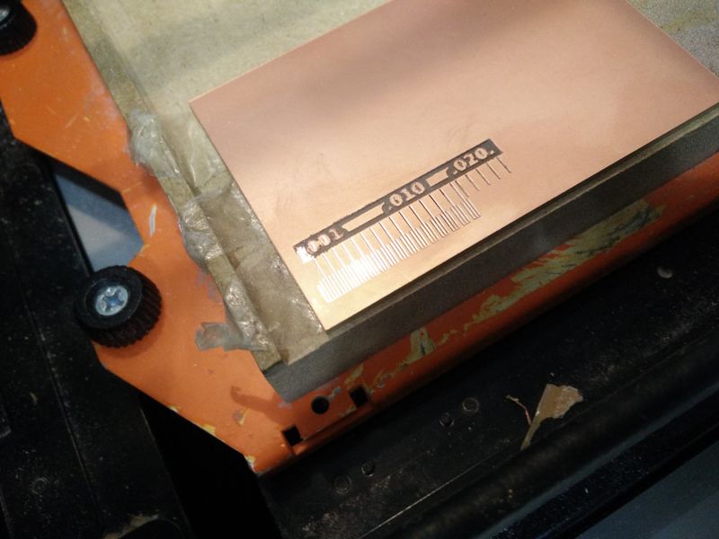
At the beginning check that the traces are getting cut through. The machine should produce a dust that is pink (copper) with a bit of white powder (board substrate). If not check the surface with the “View” functionalty and restart the milling process.
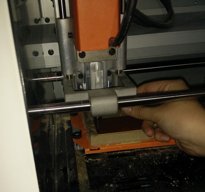
We actually faced the traces depth problem above. See image:
To make the cut deper we went back to the XY “origin” position, started the spindle and with tiny 0.01mm steps move the Z coordinate down. Try going down to -0.05 and reset the “Set origin point” with the Z button.
After the traces file, repeat the process for the board outline.
For the outline is useful to try to pull up the board before the leftover. If it does not move potentially the outline has not cut through.
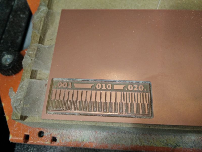
This is the final board after the scrubbing and cleaning process.
Lessons learned
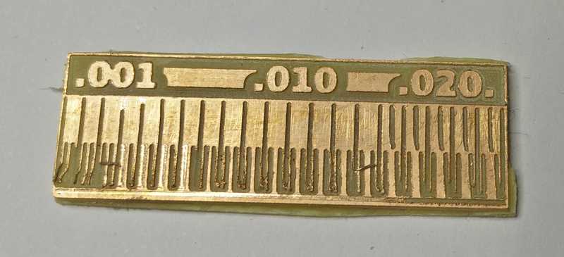
This is the final result of our board… not great quality :)
- We had an issue with generating the outline file and one of the sides of the board was not cut.
- Workaround: We inverted the image and regenerated the file so that the opposite part of the board got cut.
- General rule: Check the generated 3D shape before saving the file.
- Use http://mods.cba.mit.edu/ instead of http://fabmodules.org/ : Programs > Open server Programs > SRM-20. After that replace the “WebSocket device” with “modules” > “add server module” > “file/save”.
- Before the cleaning process small sharp pieces are on the edges of the board and from tiny leftovers of copper.
- Be careful! …and do not cut your fingers like I did :)
- After the cleaning process some of the traces have been bent and ruined.
- Be careful and do not apply to much force when scrubbing the surface.
- With the initial milling setting both for the traces and outline the depth was not sufficient.
- To fix the traces depth we had reset the Z “origin” manually two times -0.05mm below the previous value.
- We realised about the outline being not cut only after removing the board. We finished the cut by hand with a knife.
To fix the last problem in the next board for the personal assignment I slightly increased the “cut depth (mm)” used in the file generation process.
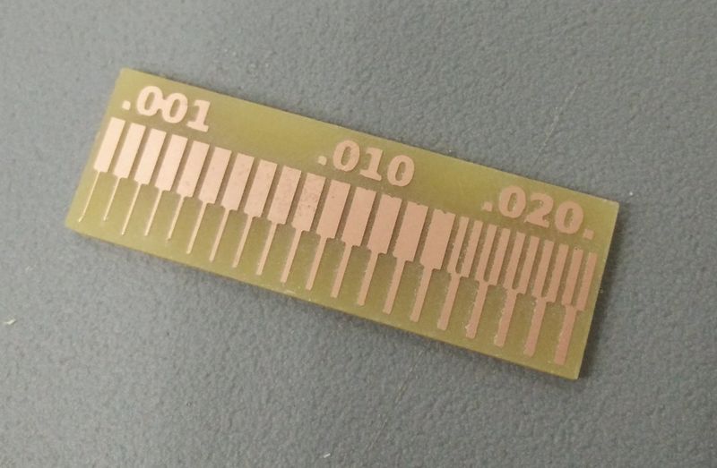
Few days later we tried with a different group reprinting the test board taking into consideration all the lessons learned and got much better results.
This is the final result of how a good quality test board should look like printed by Aitor.
Happy PCB milling! ![]()