Week 4: Electronics production
This week we followed the electronics production class (see video here)
This page is about the assignment to build an ISP programmer board, soldering components, and flashing the firmware on it.
I based my assignment on Brian’s FabTinyISP board available here.
Milling the PCB
Check this page about this week group assignment about how to mill a board.
As exercise I decided to modify the “traces” and “outline” file to include some small personalizations.
First I added my name as decoration on the PCB.
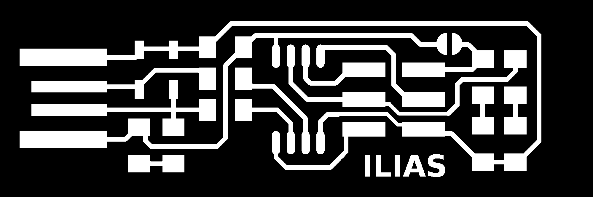
Secondly I added on the outline an extension with a hole that could help attaching it to a keyring.

Then I followed the process ad described in the pcb milling test we did earlier on the same week.
The only difference is that I decided to change of +0.1mm the stock thickness parameter to resolve the issue we faced when cutting the outline in the test board.
| stock thickness (mm) |
|---|
| 1.6 |
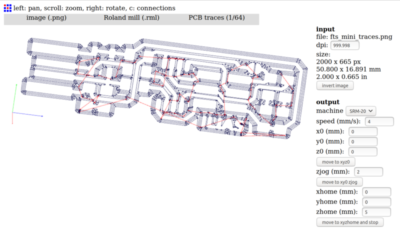
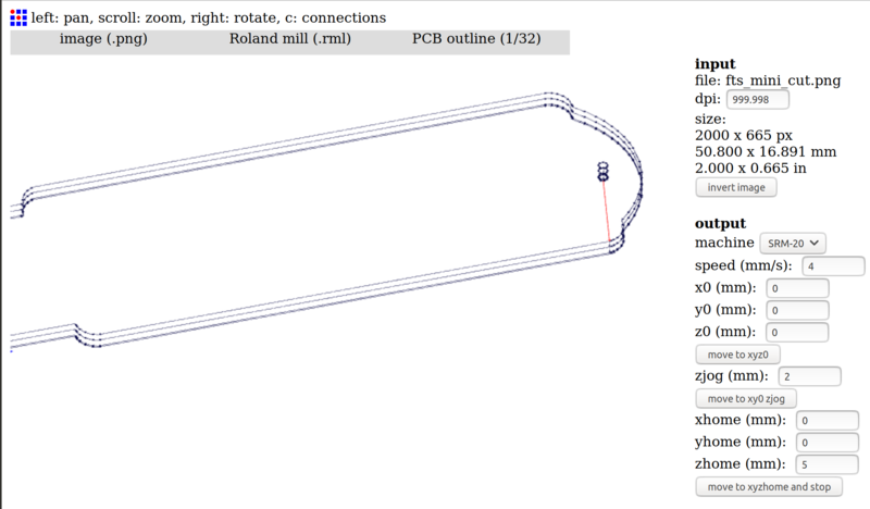
Here are the .RML files generated for my board: Download traces source file (.RML) Download outline source file (.RML)
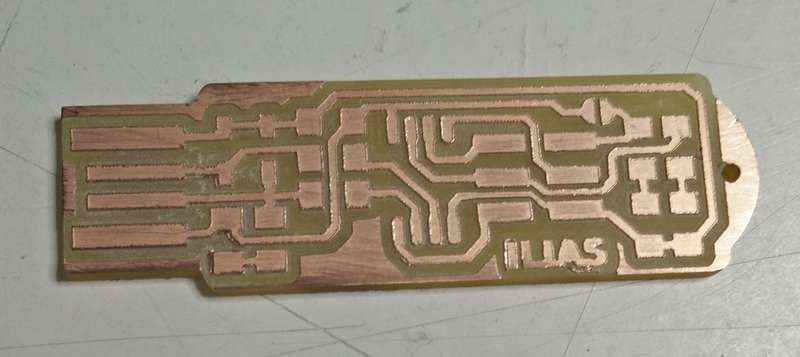
And the final result after cleaning the board:
Soldering components
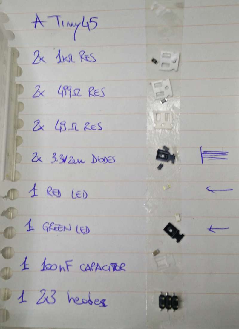
Next step is to solder the components on the board. I started collecting all the components needed on a list and highlighted the ones that have an orientation (eg. leds, diodes)
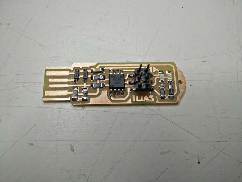
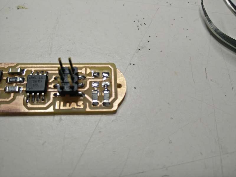
Then after a bit of practice I started soldering the components: the ATiny chip first, then the components closer to the board centre and as last the 3x2 connector header. With this order it has been simpler to have more space available while soldering.
Here is the result:
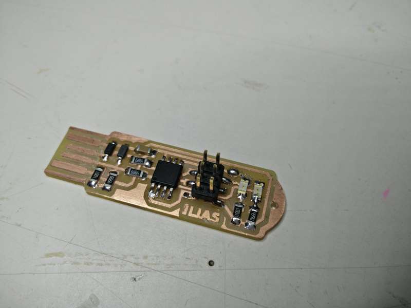
I started testing the board with a multimeter… and, oh no ![]() I realised that I inverted the LEDs orientations. So I had to unsolder them… it has been a quite gruesome experience :) and I had to ask help to a third hand in this step.
I realised that I inverted the LEDs orientations. So I had to unsolder them… it has been a quite gruesome experience :) and I had to ask help to a third hand in this step.
Programming the board
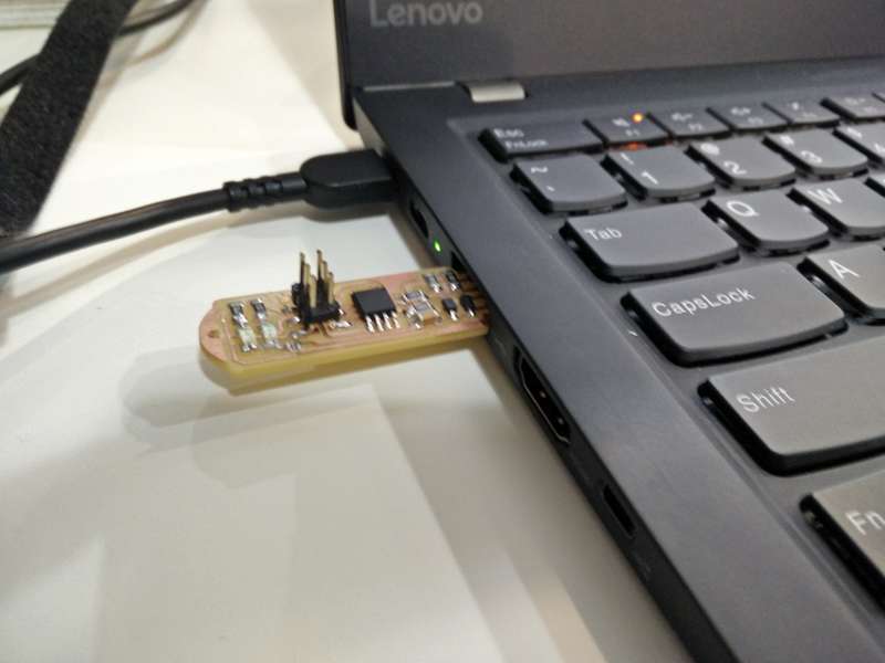
For the programming process we connect our board to an existing AVR Programmer like in the picture below:
(note: this picture has been taken later after cutting the jumper)
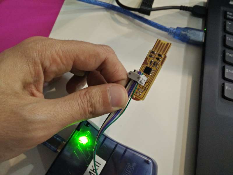
We plug both our board and the AVR programmer in the USB ports. At this point a green light on the AVR programmer gives us an indication that we are on the good path and no major mistakes on the circuit have been made.
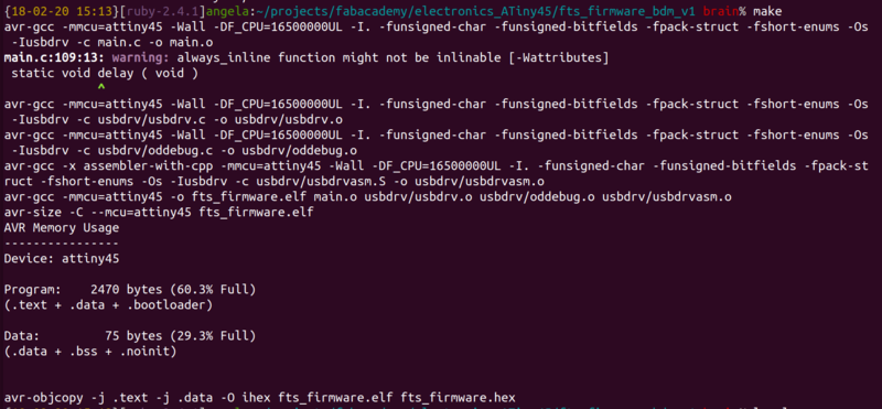
Following the documentation we flash and test our board:
- Compile the firmware binary from sources with:
make
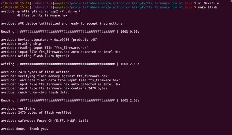
- Flash the firmware to the ATiny45 with:
make flash
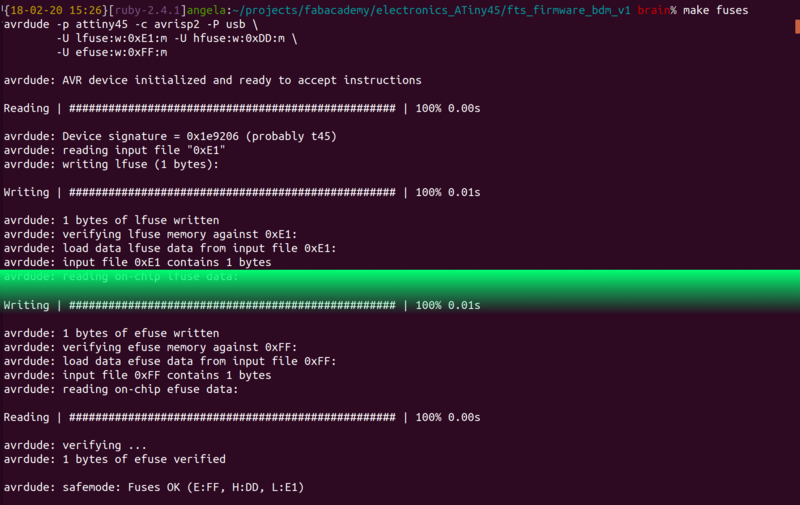
- Setup the fuses with:
make fuses
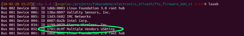
- At this poin we can test the USB functionality of our board. When it is connected to a USB port should be recognised as
ID 1781:0c9f Multiple Vendors USBtiny
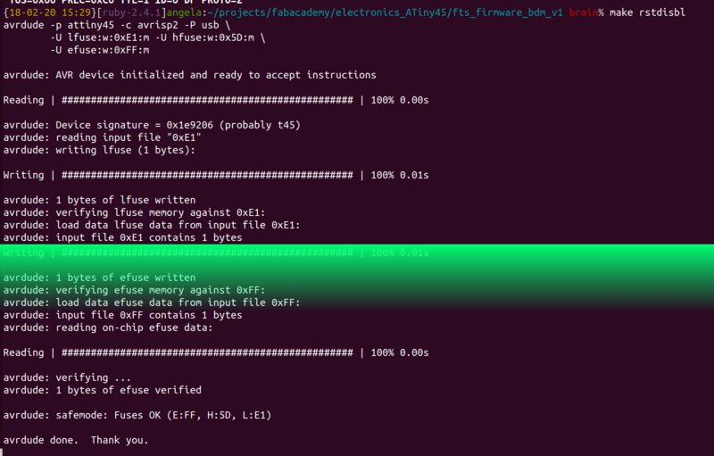
- We finally set the fuse that disables the “reset” pin with
make rstdisbl
- Last step is to remove the bridge on the solder jumper maually on the board.
Happy electronic boards production! ![]()