Week 14: Mechanical design (group assignment)
This week we followed the mechanical design class. You can see video here.
For this assignment we decided to build a camera time-lapse dolly! :)
This page is about the 1st part of the process in the group comprised by: Ilias Bartolini, Marta Bocos, André Pulcino, Óscar González
In this week I in particular contributed to:
- Initial concept and 2nd iteration design
- Creating the laser cut models and wood prototypes
- Running the 3d printing process and integrating parts
- Structure for the group website documentations
See the documentation on the group website.
Below is part of the documentation for the part that I directly contributed to in my group:
Intial concept
We would like the slider to have at least two controlled axis: (1) an horizontal rail and (2) and vertical camera rotation.
The camera would be placed on a flat plate and be supported by a conventional tripod head, attached to the plate by a screw. The plate would be sliding onto rails or tracks, and this would be moved by a stepper motor at the end of the rails. The rotation along the vertical axis would be done by a second servo motor, initially attached to the plate itself.
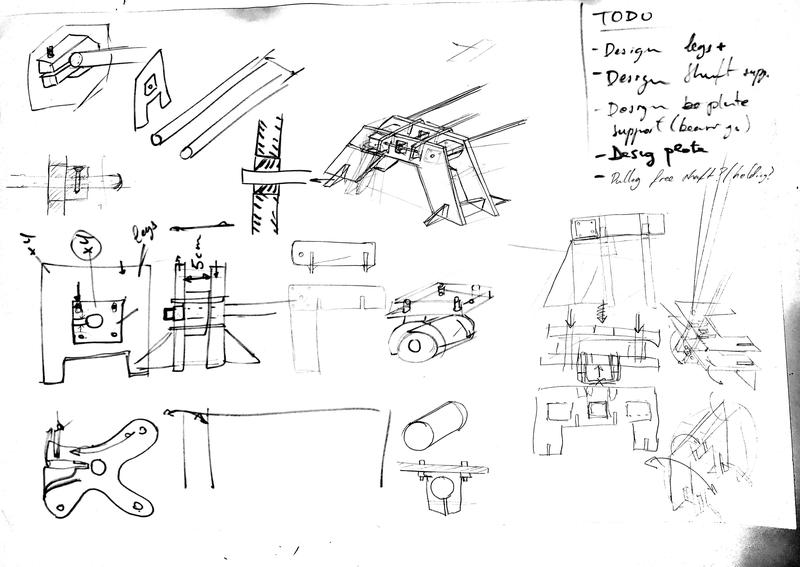
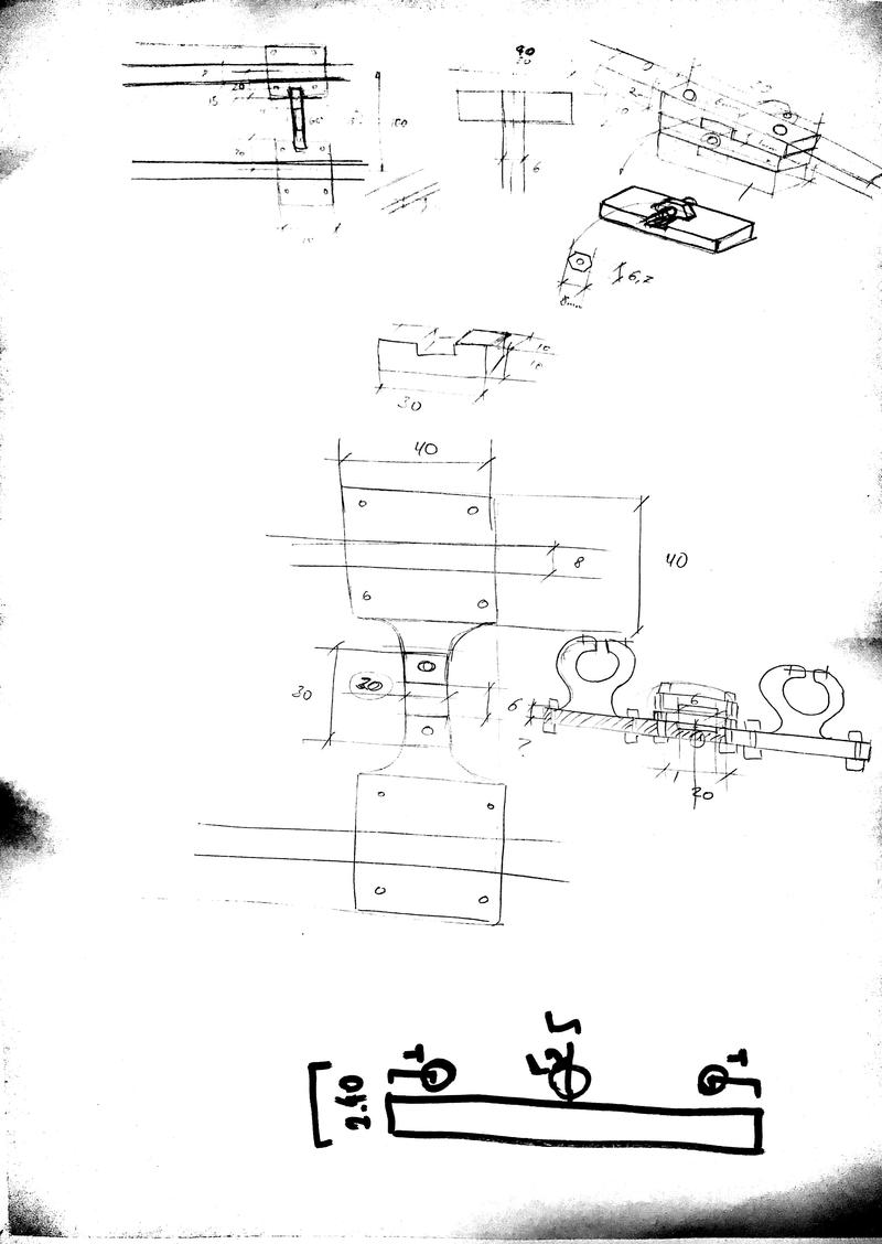
After looking at the various sample projects we started sketching together a solution. 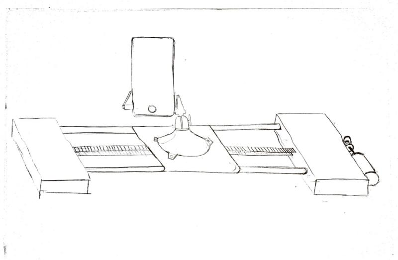
Below there is an initial list of components:
- Pipes: steel 8mm available at the lab
- Belt + pulleys: 6mm wide belt + pulleys
- End supports: to be laser cut with acrylic + 3D printed components
- Camera holder (PanaVise): to buy
- x1 Stepper motor (rails)
- x1 Servo motor (camera rotation)
2nd Iteration design:
In this section, we will describe the final solution we went for. We took inspiration from the 3D printers mechanical design such as the HyperCube Evolution and some other RepRap solutions.
The shafts would be held by the rail ends with this solution, combining 5mm acrylic and 3D printing. We decided to use 3D printed parts to hold in the shafts, making use of the material’s flexibility to tighten in the shaft:
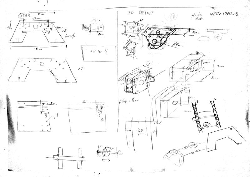
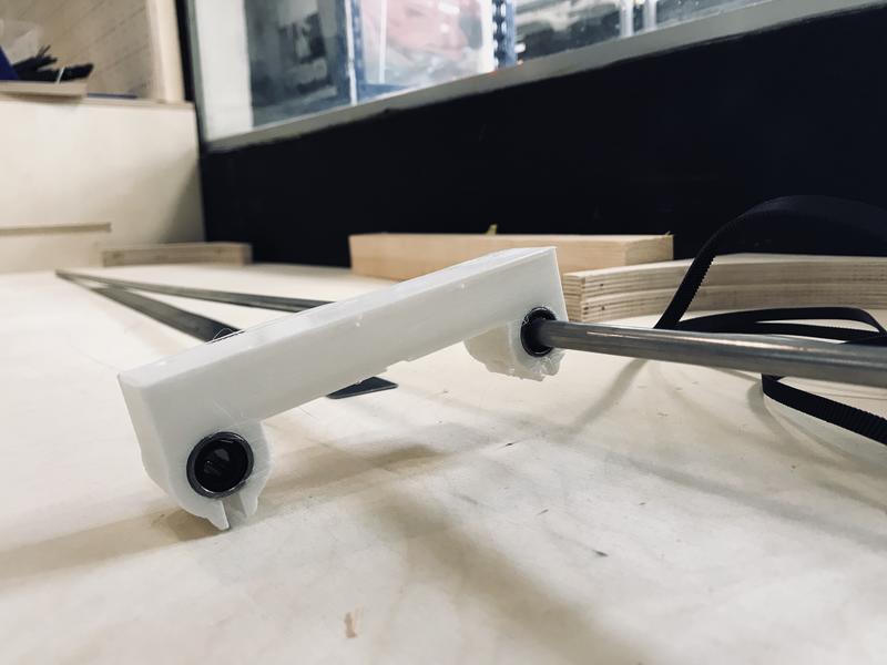
The plate would be held by a similar solution to this one. We will be using 4x linear bearings in two separate modules to be attached to the shaft.
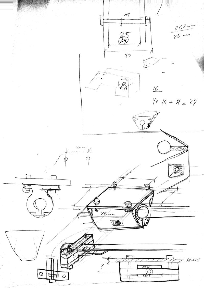
Finally, the belt would be pulling from this type of solution, so that we guarantee the belt tightening:
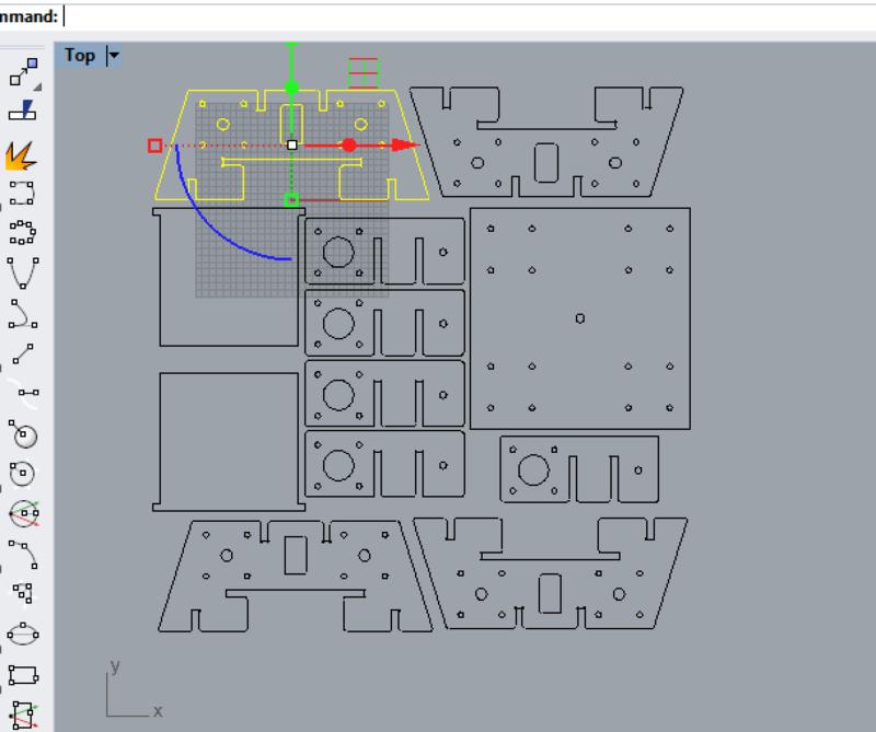
Laser cutting parts
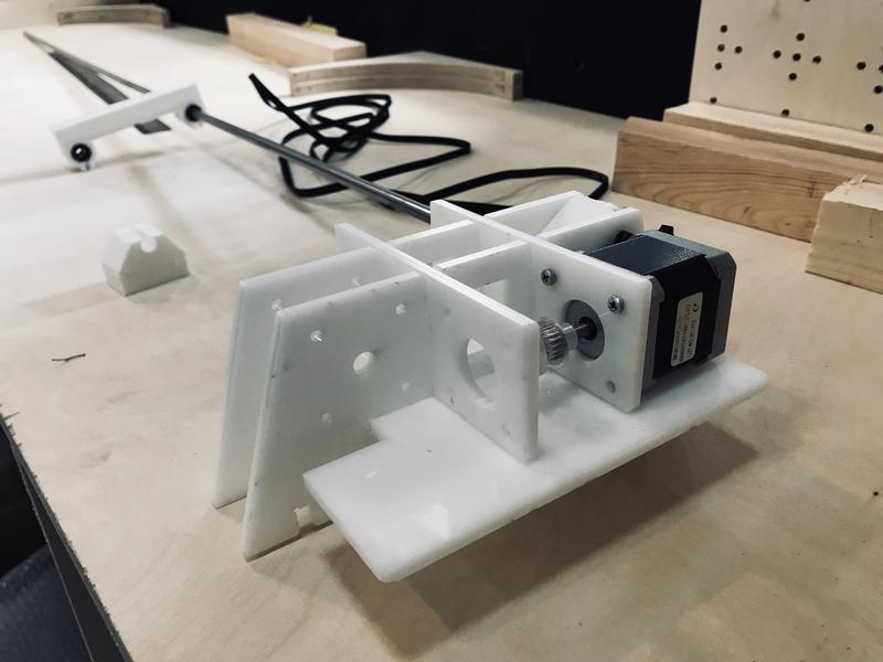
We quickly designed few new parts to build a quick prototype of the foot of our machine:
And assembled it in the afternoon to have an idea of how it would look like:
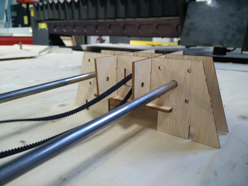
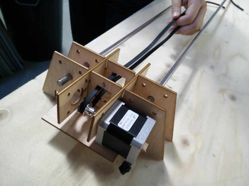
Quickly prototyping with laser cutting and plywood allowed us to quickly iterate on our design.
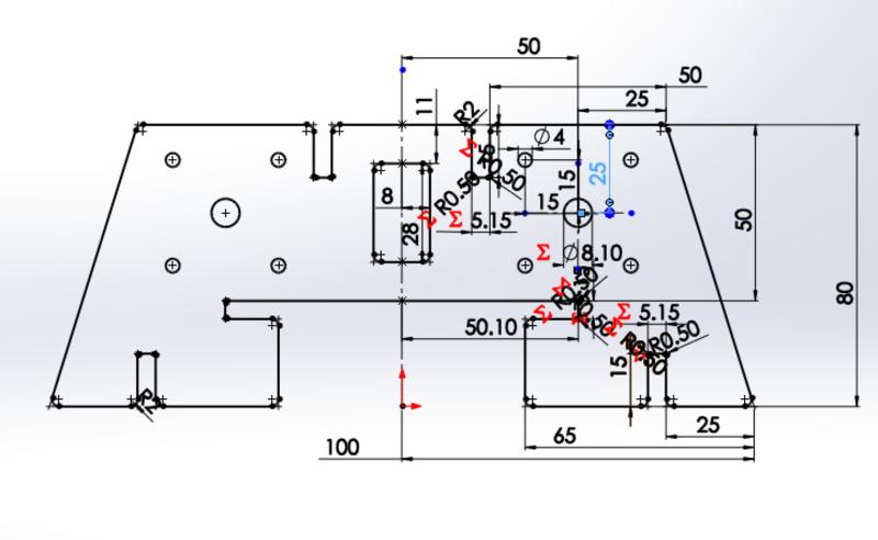
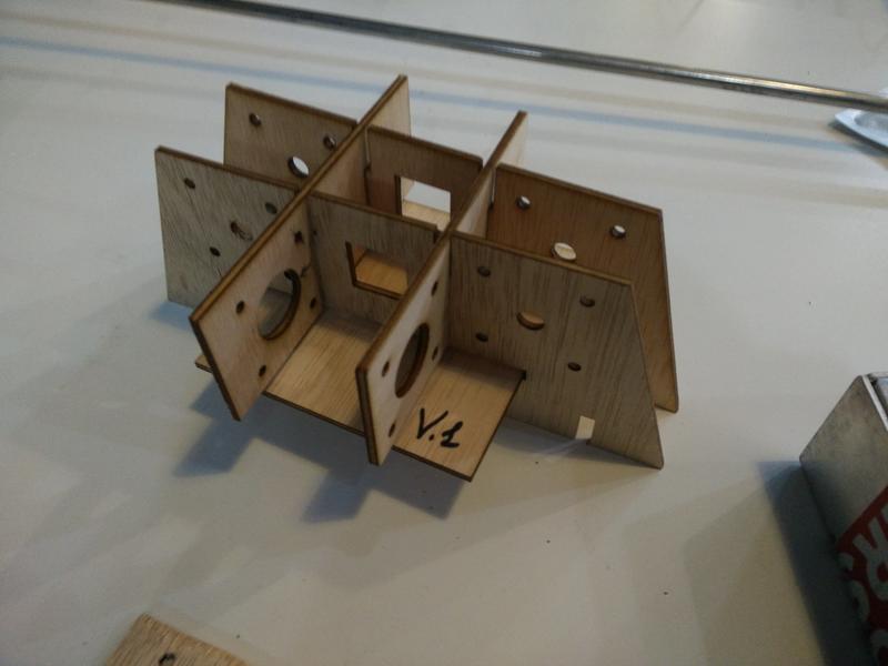
First we fixed the motor positioning, the screws holes tolerances, chamfers and dogbones: 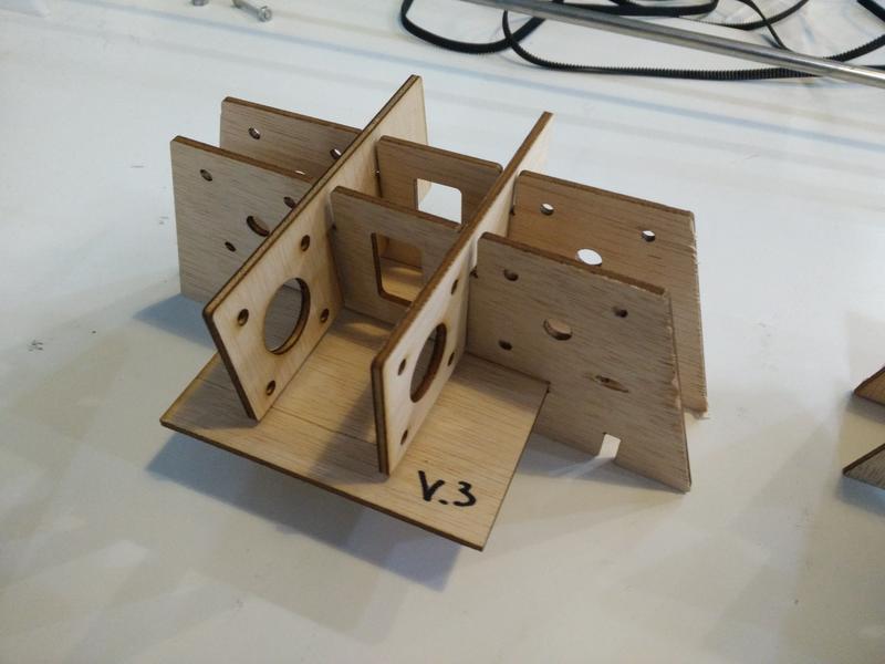
In a following iteration we increased the support plate width for the motor, added lateral-bottom pressfit parts, increased the dogbones sizes: 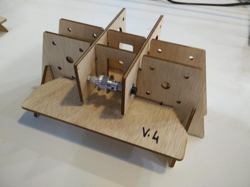
Finally we fixed the belt hole and a mistake between the bottom support plate width and the new lateral-bottom pressfit parts: 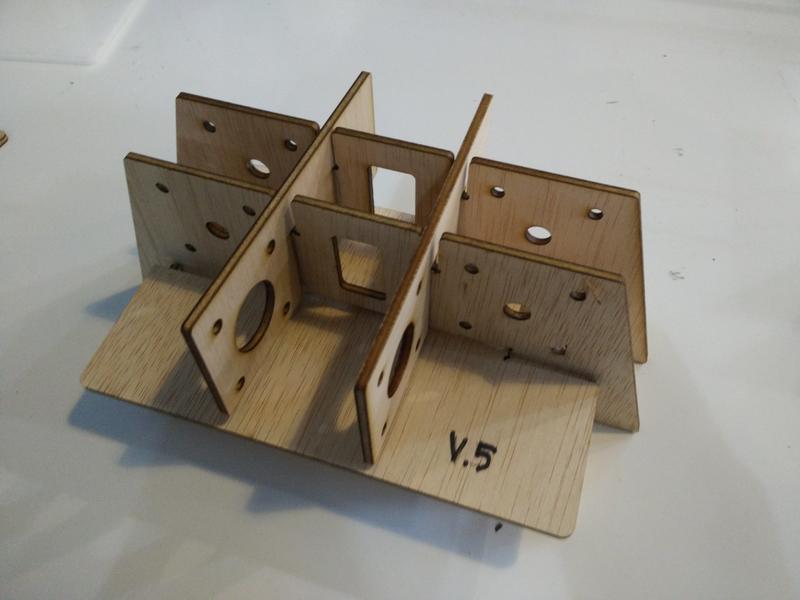
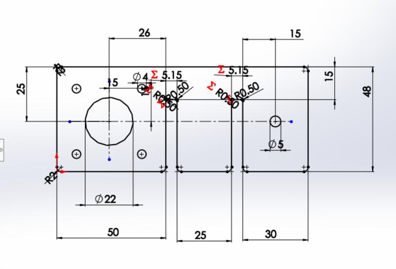
The camera support plate also went through a couple of iterations while we designed our 3D printed parts to attach to the pipes and belt: 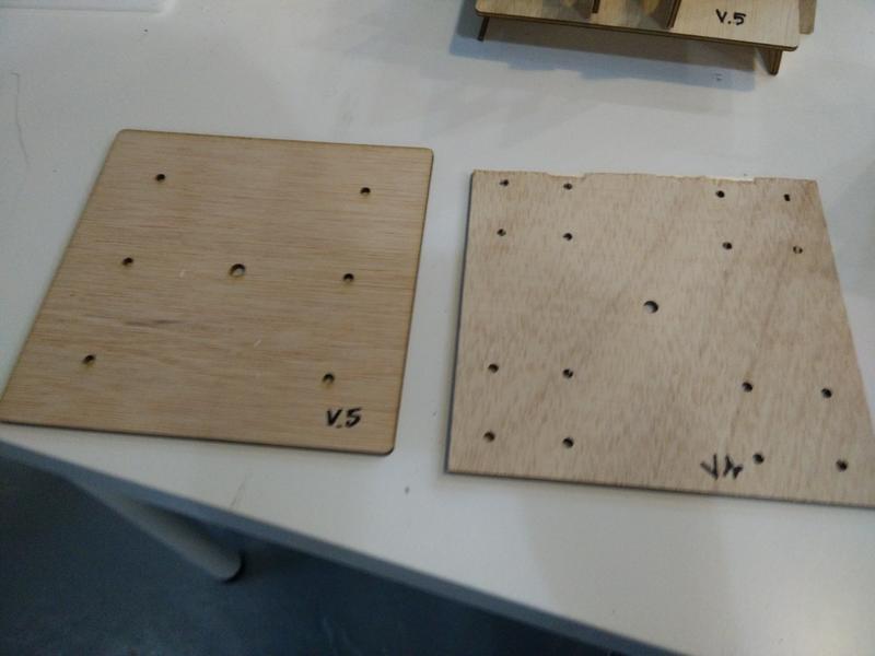
At this point we were ready for cutting the prototype in acrylic material.
Download Sources (.zip archive)
Putting it all together
Pulleys, screws, etc.
Structure for the group website documentation
For the purpose of building a group documenation website I copied the structure of my personal one that I documented in week 1 here
I only had to do minor changes:
- review some of the jekyll basic configuration (eg. the variables
/2018/labs/barcelona/students/ilias-bartolini, etc.) - removed some of the plugins for comments & analitycs (they rely on external services that need to be reconfigured otherwise)
- changed the menu bar removing personal links and removing posts categories
- changed the page “About me” to “Team” page.
Lessons learned
- Visualising things early even with simple sketches gets more important when more people are working together as a team;
- For the purpose of the first few prototypes with the laser cutter we could have easily used cardboard instead of plywood;
- 3D printing process get a lot slower with the volume of the pieces to print and the probability of failure makes it less valuable for quick iterative prototyping;
- Mechanical properties of 3D printed material relies upon highly on layer height, printing direction and positioning of the piece on the printing plate;
Next steps
- Easy to assemble platform: the clamps opening at the bottom of the platform could be wide enough to allow it to be easily detachable: currently we need to remove the foot.
- Improve the belt tensioning mechanism with a screw & bolt that allow an easy regulation.
- Check press-fit tolerances and design a way to block the bottom layer of the feet.
- Test a different solution with rails instead of pipes to limit the bending of the structure.