Assignment:
A_Understsnding feeds and speed
B_Make something BIG
C_Group assignment
A_Understsnding feeds and speed
B_Make something BIG
C_Group assignment
Understanding feeds and speeds.
Feeds ans speeds are related to the parameters to be conisdered for the tool and material interact in the optimum way so we get longest tool life, cleanest cut and fastest possible job time. There are many parameters and every machines have their own loaded presets. While it is important to undestand what is the function of all parameters it would be impossible to descriibe each of them in details so I focus on the most generic parameters and the ones needed to be considered in any job settings.
The main tools of a CNC job is the spindle and the milling bits. As there are many different types of milling bits one of its most relevant characteristic is the number of flutes - the void just before the cutting edge of the bit. It allows the material to be pushed inside of the tool and immediatly sliced away. The material cut away is called a "chip" and also carries the heat of the tool out with it. The thicker the chip that is sliced away the more heat it can carry away from the bit. They say that after a cutting job the tool should be warm but just enough not to burn your finger.
The chipload - the measurement of the amount of material that is shaved off with each pass of a cutting edge of the bit - is an important variable in defining the settings of a job. It is the result of a combination between the spinlde RPM, the feedrate (how fast the bit moves into the material) and the numbers of cutting edge of the milling bit. Using 2 of the variable makes it possible to deduct the 3rd. If we have a .005 chipload with a 1 cutting edge bit and our spindle RPM is 10 000. We can deduct the feedrate:
10 000 (RPM) x 1 (cutting edge) x .005 = 50 (feed rate).
See this guide to get more familiar with the formula.
Another very important factor to be decided when creating a job is the "cut depth" (how deep will the bit cut at every pass). The standard says that most tools are designed to cut at a depth of at least 1x the diameter of the tool. A 4mm bit cuts 4 mm per pass. But this is not a law and depends on many other factors.
Plunging rate has to do with how fast the bit plunges into the material.
Climbing/vs/ conventional cutting: the direction the tools travels around the toolpath. clockwise or anticlockwise. Can affect the finising quality of the job.
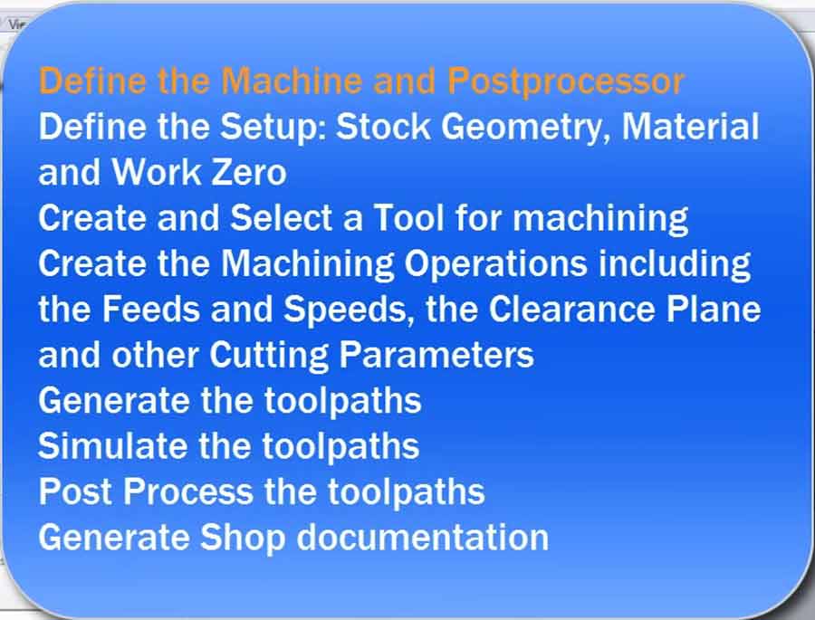
Milling Strategies and operations
Strategies have to do with the order in which the operations will be performed. Main operations are:
- drilling = drilling holes - the milling bit is the same size as the hole to drill.
- pocketing = milling bit empty a closed area of material at specific depth - can be to drill a hole with a bit smaller than the size of the hole to drill.
- profiling = milling bit cutting through the materials traveling either inside or outside the line.
- engraving = milling bit travels on the line - can be to engrave on the surface of the material or cut through.
The order in which the operations will be performed is mostly defined in consideration with the 2 following factors: minimizing tool change and keeping the material as strongly attached to the machine bed as possible.
Note: The terminology may vary from one application yo another but they all refer to these type of operations. And those are the generic and more often used by makers but far from the only ones.
Workflow
The workflow for CNC milling is similar to Milling PCB. The difference is in the scale of the components involved.
1º - make a CAD design - make shure all lines on the same planar surface and closed.
2º - create setup and toolpath - create all operations and decide which order the CNC will perfermed each of them.
3º - generate Gcode - select the approrpiate post processor for the machine to be used and export the gcode file.
4º - mill the object - import the gcode in the machine job controller, place material on machine bed and milling bits on the CNC machine, set the zeros and send the file to mill.
5º - Finishing - sand and assemble the pieces.
In other words:
Notes: It is highly recommended to check, double-check and re-check the files and strategy before actually going into milling. Working on a full scale CNC mill can be dangerous and require high level of precautions.
Designing for milling
Experimenting with the workflow from design to a CNC fabricated object.
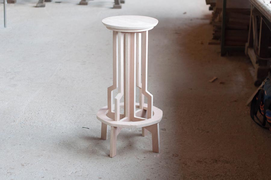
For this exercise I fabricated in real size a new Twistab model I had done last year in miniature and that I had laser cut.
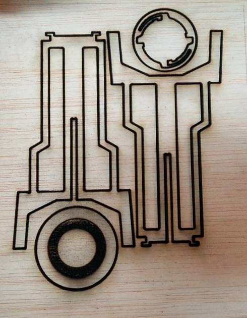
Apart from an opportunity to practice designing on Rhino, this exercise is about getting the file ready for fabrication. The different step of the process are: preparing the file, nesting the pieces, make the toolpath, generate the Gcode and mill.
When scaling the miniature model to real life size I added quite a few details which could not be implemented in the miniature scale. For example pocketing on the reverse side of the footrest, the external diameter and review the shapes of the inside hole of the legs, and adjust the tolerance.
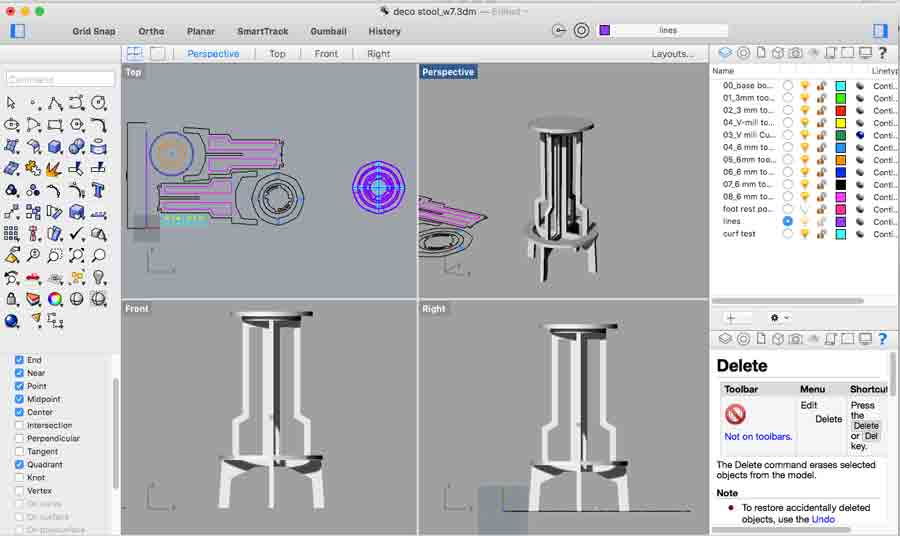
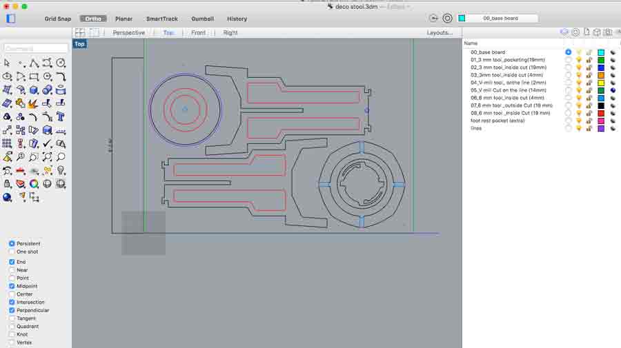
When preparing the file it is important to make shure there are no repeated curves and that each curves are all joined. A gap in a curve will clug the workflow. Make shure all curves are joined, then select all curves and enter tne "make2d" command - eliminate hidden elements in all planes. This command sends all the elements on a new layer called: make2D so the old layers can be deleted.
Another helpful command to make shure all the curves are on the same plane and not repeated is "planar srf".
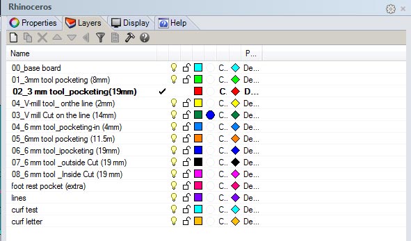
Next I created the milling strategy, reassociating each layers to groups of objects. Each object has a color and a function. (I still have a lot to learn as per the best method using color and to organize this part of the workflow)
Preparing the job/Making the toolpaths
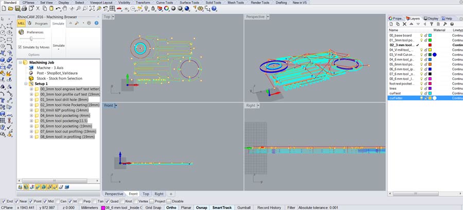
I used Rhinocam an a Windows to create the toolpath. I am looking for an open source solution but yet has not found it. I have used the shopbopt interface directly in the past but not Rhinocam yet. This RhinoCam 3 axis tutorial got me confident and I went on making the toolpath.
I will be milling with a fullsize Shopbot and reviewed the Shopbot part of the Labs wiki before proceeding. The postprocesor of the Rhinocam installed on the lab computer are already set this shopbot so I could go on making the toolpath directly.
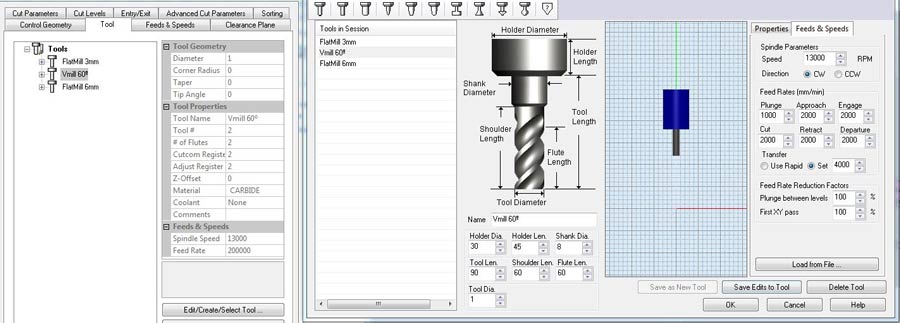
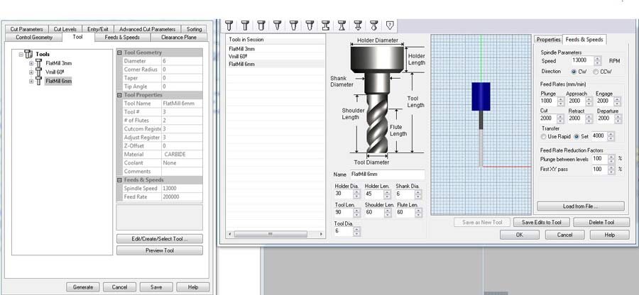
I am using 3 tools for this job (3mm. and 6mm. flat endmill and a 60ªVmill bits). I could do without the 3mm. but I will prepare it anyways.
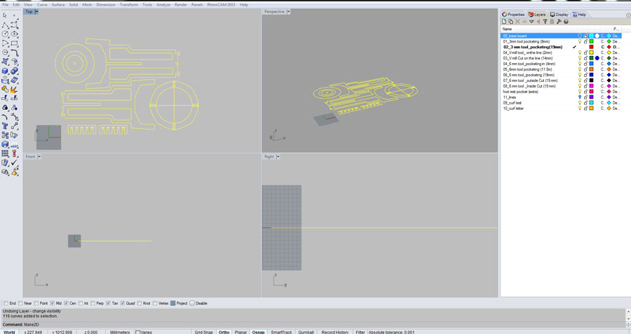
I started by creating the stock - 1250 x 2500 at -18 mm. The -18mm is so the 0 of the Z axis is on the top surface of the board.
u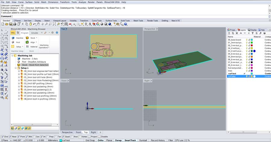
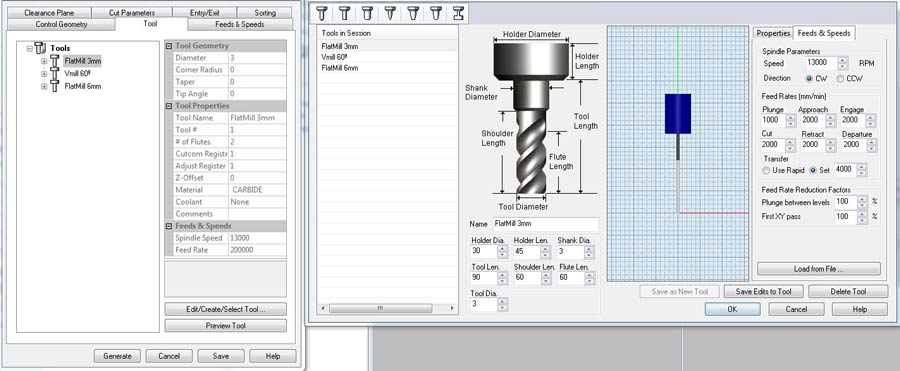
After I set the 3 tools that I will need: a 3mm flat end mill (for the screws that hold the board and the corner holes), a Vmil 60º to chamfer the top disk of the seat, and a 6mm flat endmill for the rest of the job (pocketing and profiling).
I set the the "feed and speed" parameters for each tool as specified for the specific shopbot I'll be using.
Since all the infos about tools, milling depth, inside/outside/on the line and the type of machining (pocketing, profiling etc.) come from the Rhino layers all I need to do is translate these infos into each toolpaths.
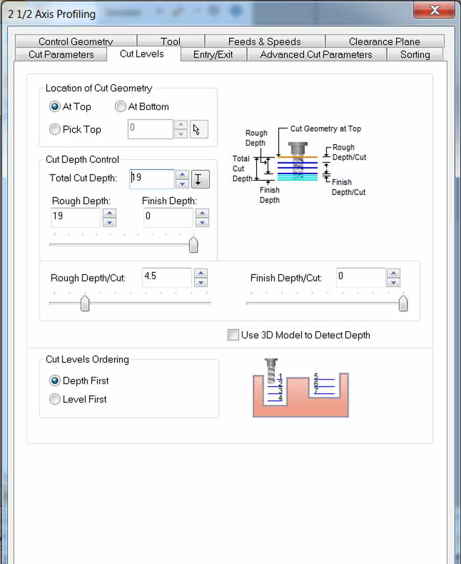
I am using "drill hole" function to drill the holes where I want to put screws that will hold the board to the machine bed. I used also "drill hole" but at 19mm deep for the whole in certain corners of my design. I set it up to drill the total depth of the whole at once.

I use pocketing to empty (retrieve)material in some areas between 2 curves (below part of the seat) or within the circle which diameter is bigger than the size of the endmill.

I use profiling for the part to be machined with the 6mm endmill. The curves located on the external contour are to be milled outside the line and the ones that are located inside the shape of the stool will mill inside the line.
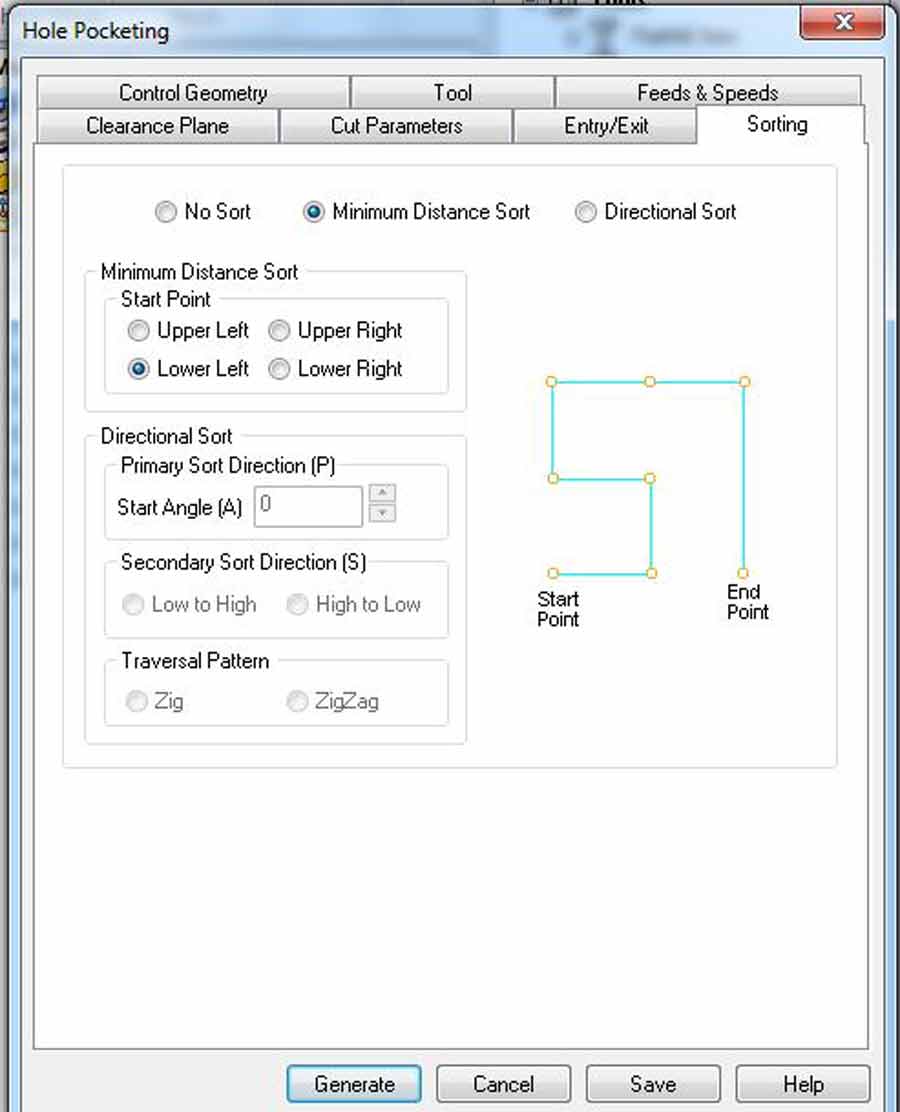
In each toolpath I set the sorting tab to "minimum sorting distance" so the machine follow the shortest path throughout the job. That helps speedup the job, save time and be more efficient.
I also integrated a .5mm tolerance kerf test for 18mm plywood and created the tool path for it. The kerf test is milled first and before making the toolpath so the join and slotting part of the design can be adjusted according to the kerf test result. In this case I adjusted the file simply by scaling the whole design to 18.1 mm. for the slotting part. In the case of having the design parametric just adjust the corresponding parameters.
I am using material that I have used in the past and know from experience this type of plywood (18mm okume plywood) has to be milled at 18.1 to get the perfect slotting.
The total milling depth is 19mm and it will mill 5mm depth at each pass. That means 4 pass in total. I used these parameters for every toolpaths.
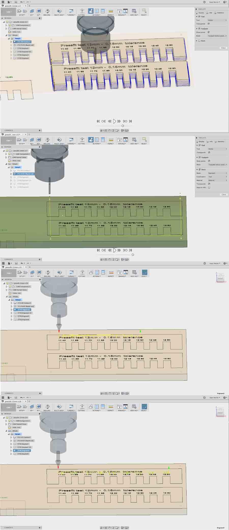
The following images shows the complete tool path and a simulation of the actual job.
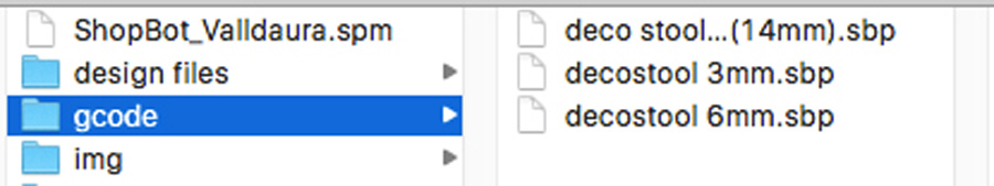
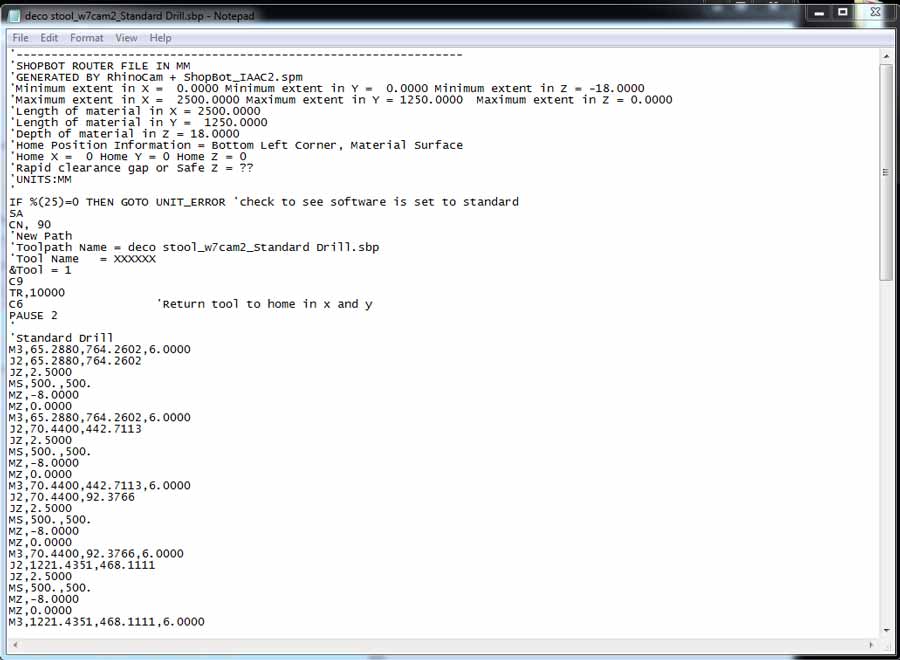
Generating the Gcode
Once each tool path has been created the Gcode has to be generated. I selected all the toolpaths associated to a specific tool and post it to generate the Gcode. I repeated it for each different tool, ending up with 3 gcode files.
The Gcode can be read and analysed to verify the job is correctly programmed. It consists of a series of information related to the miling parameters the machine will execute and sequences of XY and Z axis coordinate. It is possible to edit the Gcode directly from the text file.
Milling
To actually CNC mill the job I am using the Shpbot cnc interface which is the native software to run Gcode on Shopbot machine.
Before anything the board needs to be placed on the machine bed and placed properly in the corner where the XY 0 of the machine will be set set.
Next I loaded the Gcode file with the shopbot cnc software.
-Open the shopbot software
-menu file/open file/part of the job to be milled
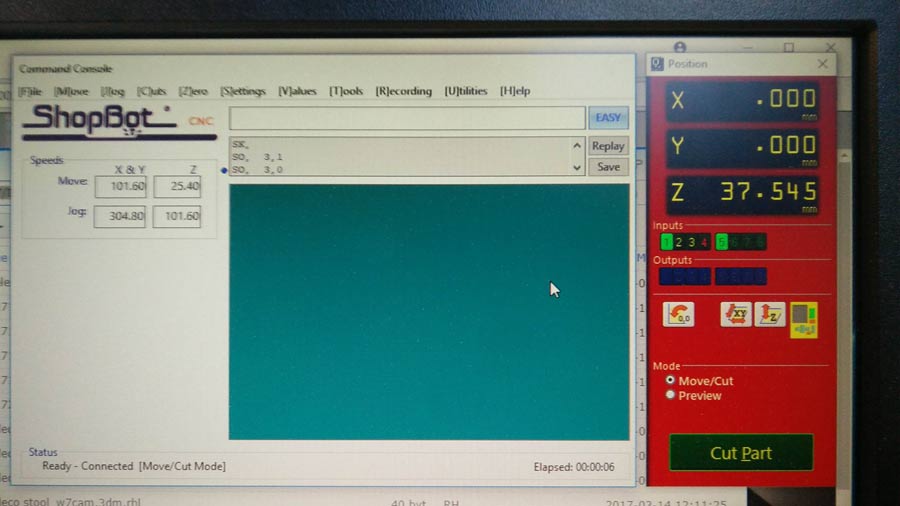
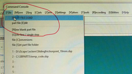
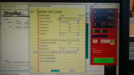
- A part file load page fills the screen- press ENTER and it disappears.
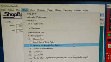
- open cut menu/C3 Home X Y axes using Prox switches (this send the machine spindle to the machine X and Y zeros).
A subwindow pop up to control the spindle position and set the XY 0 and the Z axis 0.
-Use the arrows to move the spindle to the desired position - that is to the position of the board where the job shall start.
- click on the little blue window that says: zero axes. A new window opens.
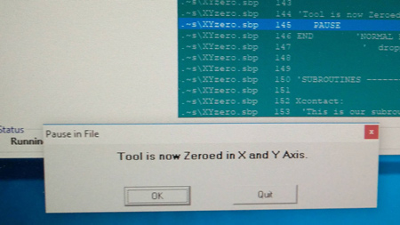
- Click the x and Y box and then ZERO (that sets the x and y zero in the current spindle position.
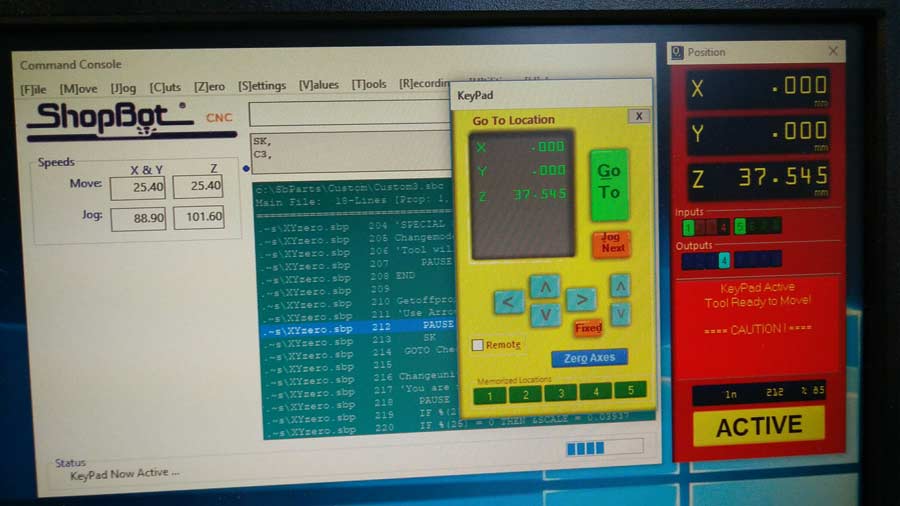
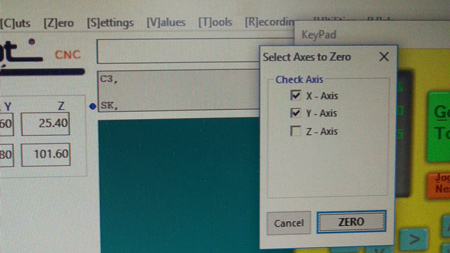
Move the spindle to desired Z position (just at the precise point where the bit touches the material), open the zero miniwindow and check the Z box and then click ZERO.
Now the machine is ready to start the job.
- note that it is important never to change the X and Y zeros within a job. But with every new tool change within a job the Z axis 0 had to be reset.
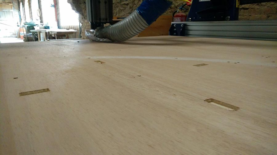
I stated by drilling the 8mm holes to screw the board to the machine bed.
When screwing the board to the machine it is important to make shure the screws are tight enough so the board lay completely flat on the sacrificial board (the board that we place our board on).
Than I sent the 3 mm. drilling holes (for the corner where I needed a 90º angle joint) and the pocketing of the footrest.
And the the 6mm. pocketing and profiling.
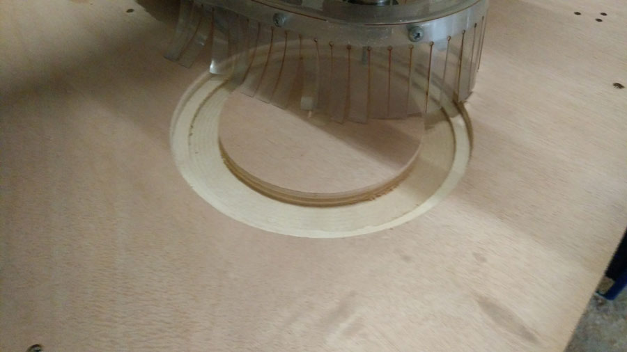
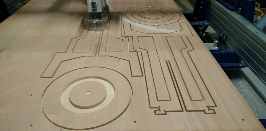
The job came out pretty well for a first prototype, enough to get conclusion in terms of the proportion of the design and have the possibility to physically see the details and flaws.
The most important details that failed was the pocketing of the footrest. I made a 4mm. deep pocketing the size of the material (18.1mm) but it came out narrower so I had to chisel material out to make it fit. The reason is that I had set the toolpath "inside the line" while it had been designed to be on the line.
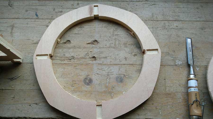
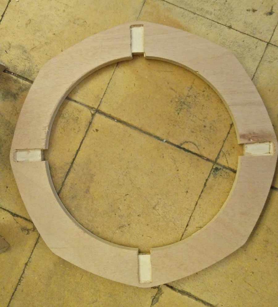
For the rest of the pieces, a little filing did the job and it slotted, assembled and fitted easily.
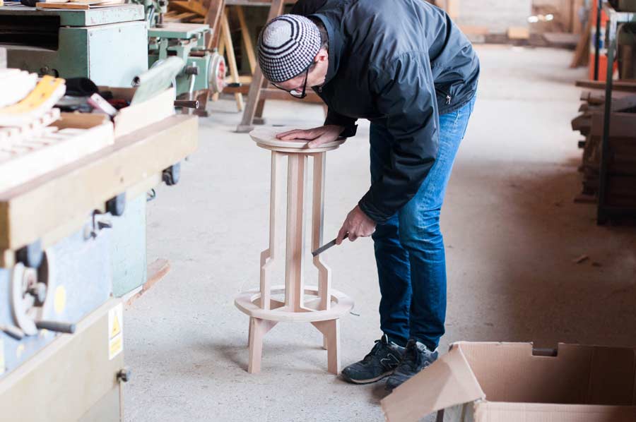
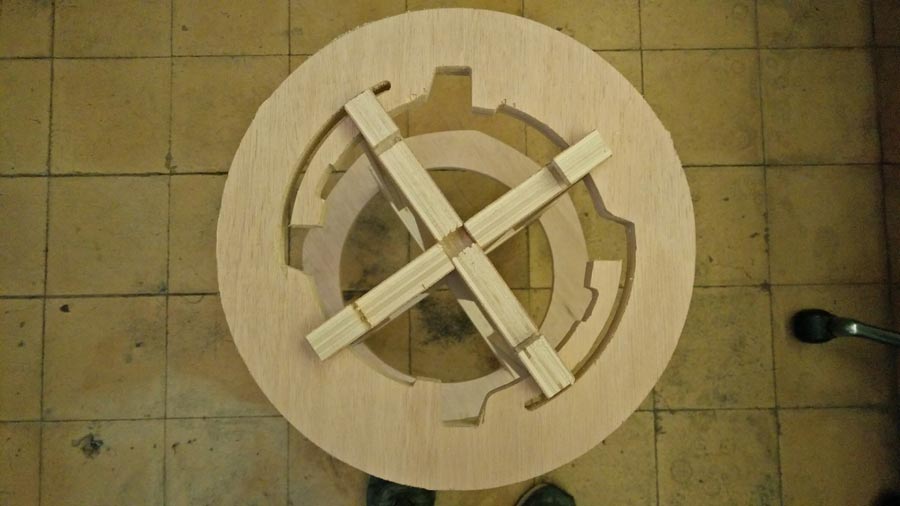
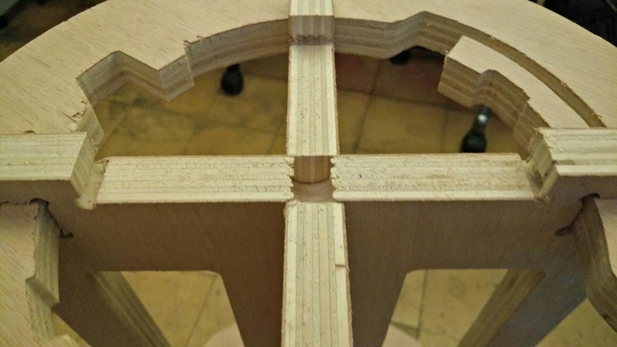
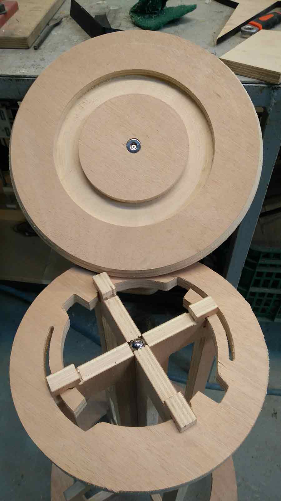
This Twistabis a swivel magnet version - the seat is joined to the legs using a magnet system - A 18mm steel ball is inserted into a whole pocketed in one of the leg and a washer magnet is attached (screwed) inside the pocket in the bottom part of the seat. So the top disk (seat) is attached and can also swivel.
To get a final version of this model I will adjust design and technical details.
Group assignment
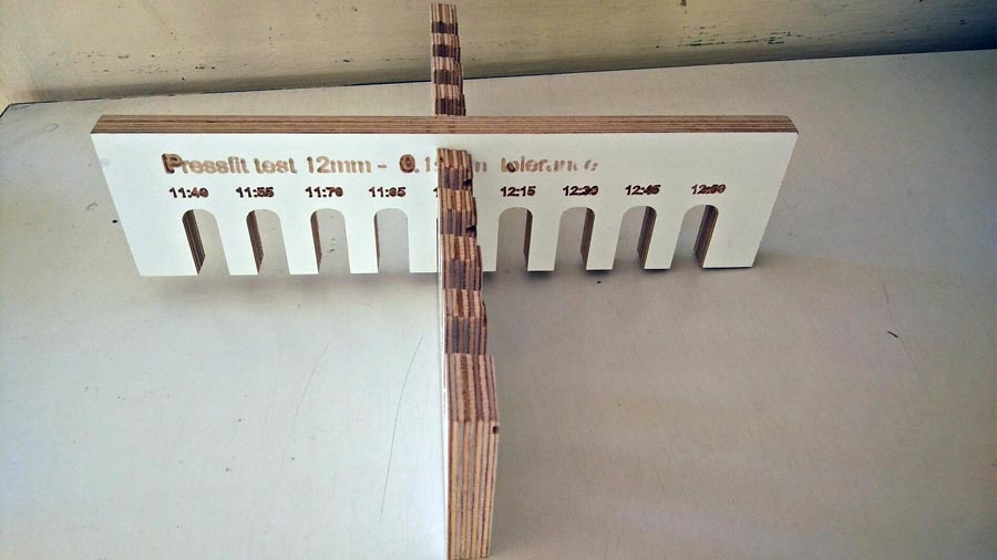
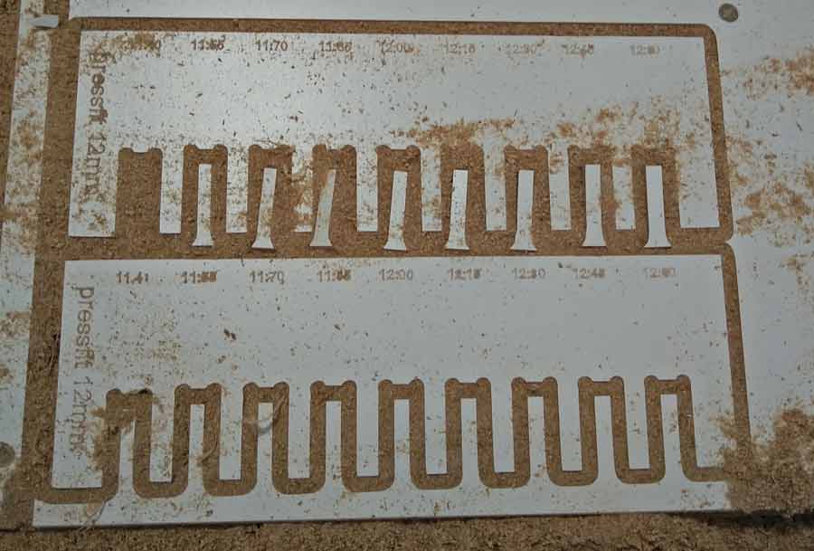
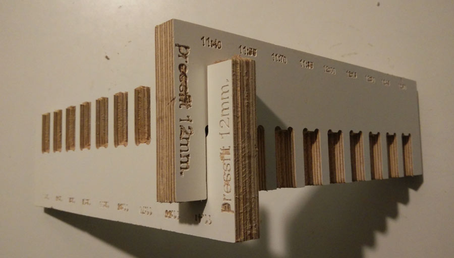
To avoid my group assignment to be redundant with my formal assignment documentation (in which I have integrated Rhinocam and Shopbot processes) I am documenting making toolpath using Fusion360Cam and milling on my own small open source Good Enough CNCmachine which I recently acquired. For the exercise I will be milling a pressfit test for 12mm. plywood.
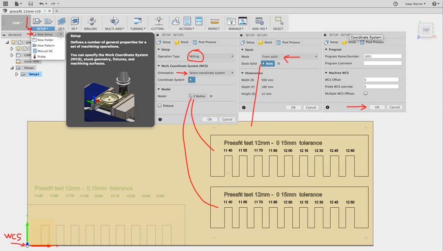
I am using the parametric file I designed on the 2nd week assignment and will use Fusion360 to create the Cam file. With the file open just switch to the cam tab on the top menu and created a new set up. Right clicking on the setup tab opens a new window in which we define the setup, the stock and the post process. In the setup I defined the type of operation (milling), the world coordinate system to model orientation and the origen to model box point and selected the origin point corner of the model. Then I selected the 2 bodies to be milled. Then I defined the stock as a solid (i had created a body for that purpose) For the post process I just left the WCS offset to 0.
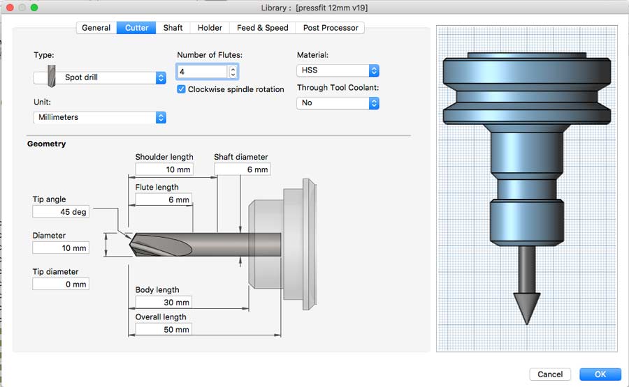
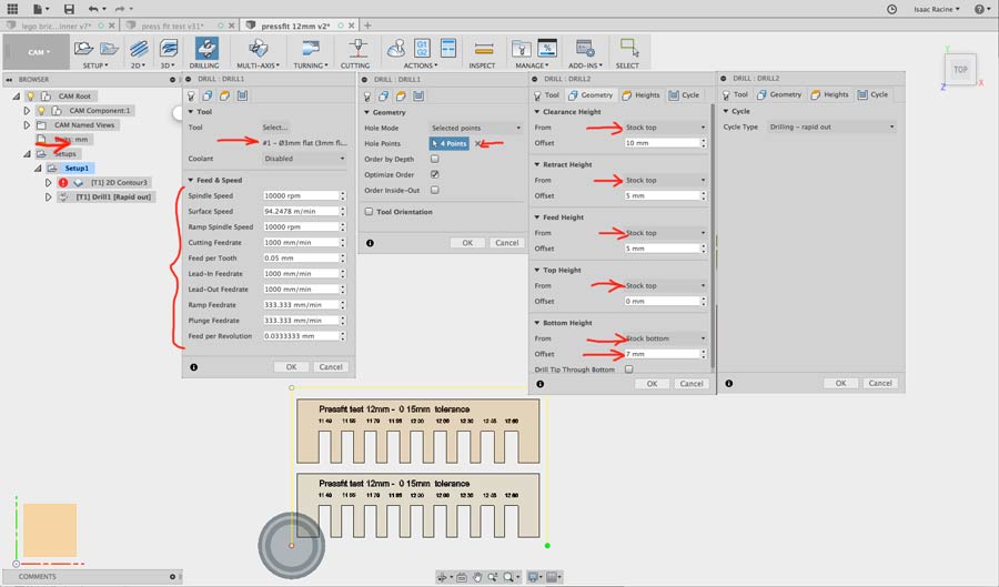
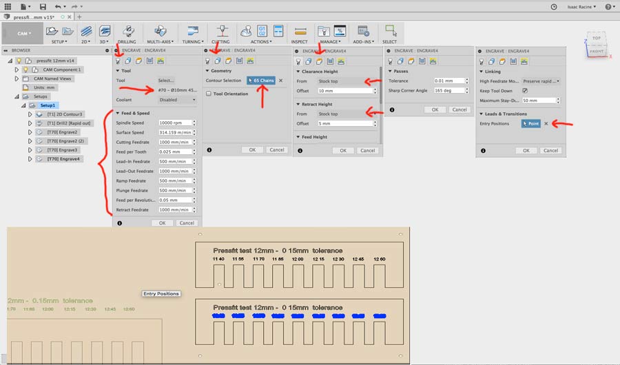
After completing the setup I selected a 2Dcontour toolpath from the top menu. This opens a new window allowing to set up the toolpath parameters. I started by creating the tools I will use for this job. That is: a 3mm flat end mill for drilling and contour (profiling) and 45ª spot drill for engraving the texts.
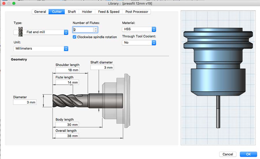
After selecting the 3mm endmill bit in the tool tab of the setup window I set the RPM to 10000 and left the other fields as the preset suggested. They seems good so I'll see after miling if there are needs for adjustment. I have no experience wiith this CNC yet.
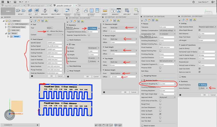
-In the geometry tab I selected the 2 bodies to be milled, defined the tab lenght and height and placed 4 on each bodies.
- In the Height tab I set everything in relation to Stock top, left 10mm. clearance and 5mm for retract and feed, set the top at 0mm. from stock top and added 0.15mm below the stock bottom to make shure it will mill through the stock.
-In the passes I kept it all as the preset suggested except for the "multiple depth" which I set to 2.1mm (every pass the bit will mill 2.1 mm deep of stock).
-Finally in the linking tab I just choose the starting point of the milling job.
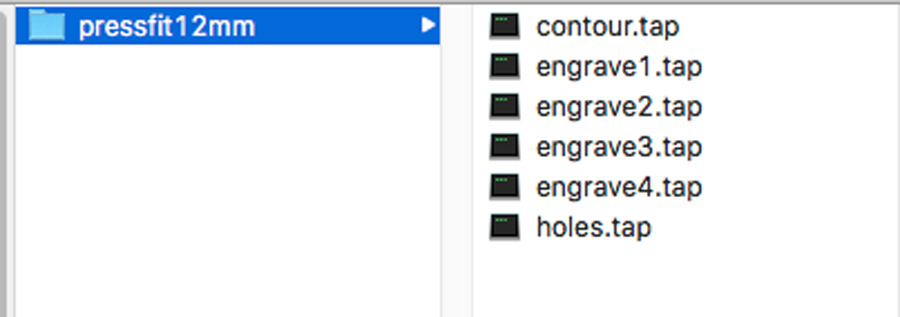
I went through setting up the drilling (hole to screw the material to the machine bed) and engraving (texts) operations. For the engraving I divided the job in 4 parts as it took a lot of CPU power to process it all at once.
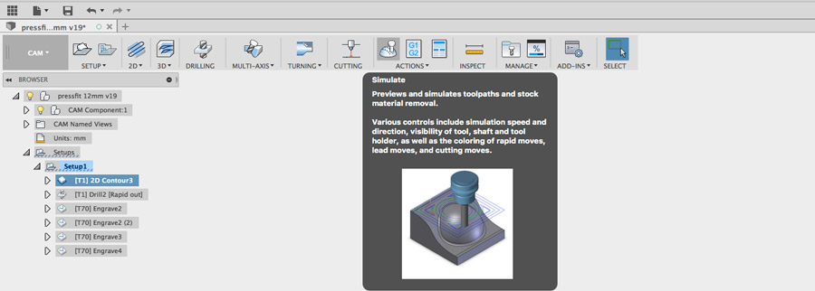
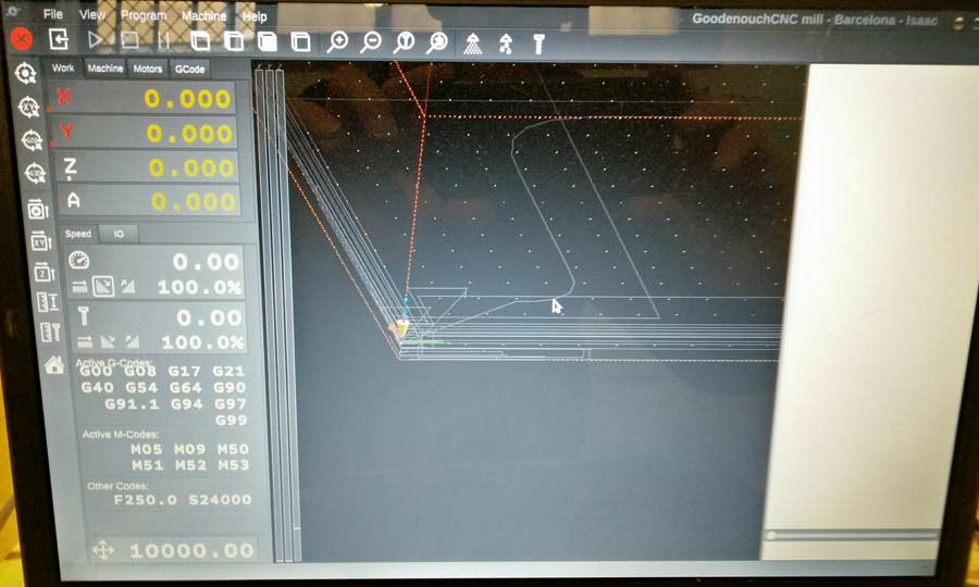
Once the toolpath is created it can be simulated by pressing the "simulate" booton on the option tab from the top menu (or right clicking). Once the simulation is activated the model appears with the toolpath, control keys at the bootm of the screen and a window with various setting for the simulation. Pressing play shows how the job will proceed.
Also in the action tab there is a subtab to post-process the files. The window that opens allows to select the source, the post processor, name the file and choose the units. My CNC is configured for Mach3mill post processor which is generic. When accepting a new window will open asking to choose the location where to save the Gcode. By default Fusion 360 saves the file to a self created nc folder in the Fusion360 folder on the user folder - but it can be rooted to any folder. The file created is a .tap file but it actually is a simple text file and can be opened in any text editor.
The G-code is basically a series of coordinate orders for the job to be executed. At the beginnig it sets up the job (spindle speed, feed rates, etc) and the coordinate on each axis of every position of the milling bit throughout the job. I found this G-code translator that was very helpful to understand what means what in Gcode language.
Milling the pressfit 12mm test
Before even starting it is important to make shure the machine is set properly and match the WCS of the file. X and Y zeros are by default set on the bottom left corner of the machine and the Z zero on the surface of the sacrificial board. I use a small application called Planet CNC. The machine designer has given me a preset file that guarantees all the ports and setting are suited for this specific machine. I personalized the motor limits and the ranges (they both have to match exactly) to be able to use maximum area of the machine bed on both axis and limit the margin to -3mm on the z axis so they is no risk to mill into the sacrificial board. Lastly I set the machine and work zeros on the 3 axis.
Then the stock has to be placed on the machine bed and fixed properly so the friction of the milling bit won't make it move. The position on the bed and on the Cad drawing has to match exactly. In my case the file to be milled is ofsetted 265mm on the x axis and 25 mm on the y axis from the WCS on the file so I placed the stock in a position with the same offset on the x and y axis. Then I loaded the Gcode files and started the actual milling. Beeing new to both the machine and the software I struggled quite a lot before understanding that in the settings the "limits" and "range" has to coincide perfectly.
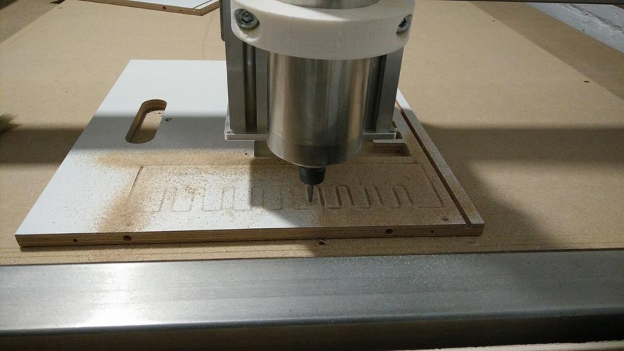
For beeing the first time milling with this CNC it went pretty well though far away from perfect. Some mistakes are due to the files, cam setup and my lack of experience with Fusion and others because the machine is not properly set.
1º -I had compeltely forgot to insert dogbones. I found out there is an Dogbone addin for Fusion that makes easy to add dogbones to existing sketch and most of the time they work with parametric aspect of the design.
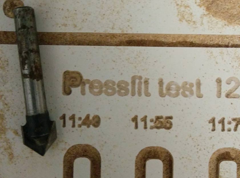
2º -For the engraving I had chosen a 90º Vmill bit but the tip of the tool I used is not completely sharp so I finally replaced it with a small 1/32inch recycled bit (it had broken and we rescued it filing it with a dremmel) and it gave better result.
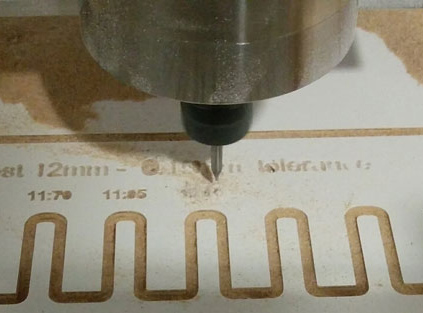
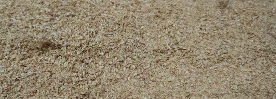
3º -The relationship between the spindle speed and the feed rate and dept of cut was obviously not righ judging from the chipload that is completely dusty. Spindle spped was way too high (20 000 RPM) and the depth cut only 2 mm for a 3mm bit.
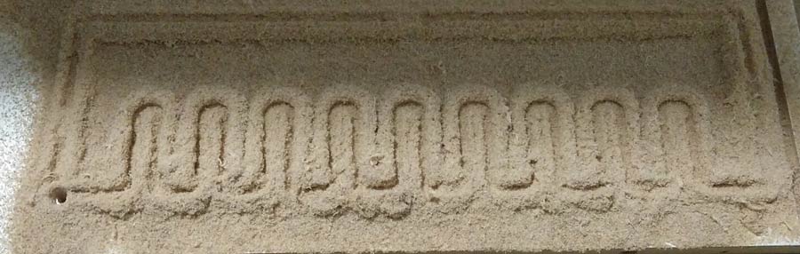
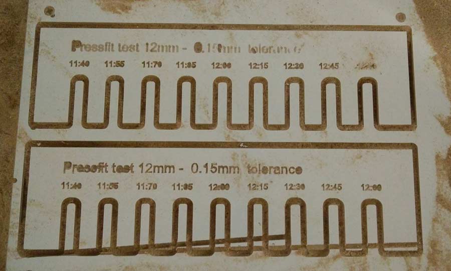
4º -As we can see in the following pictures the engraving is correct on the right hand side while barely unreadable on the left hand side menaning the machine is not on the x axis. Solution to this will be to mill the whole bed surface with a T-slot bit which I will do eventually.
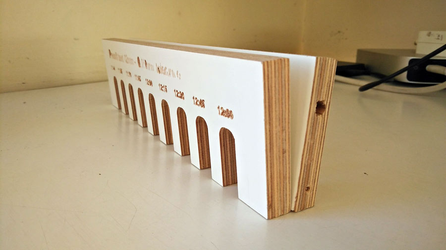
5º -But before anything I will need to level the up the mechanical Z axis unit. The cutting angle is not at 90º. When resting the cutted pieces on one of its edges one notice the inclination.
6º - I noticed an offset between the measurement of the slots of the cad file /vs of the milled piece. For example the cad 12:00mm slot came out as 11.50mm which is quite a difference. This has to do with the calibration of the Step/mm on each axis which I took for granted as they came as presets but they seem not to be so accurate.
This test is conclusive in terms of learning the workflow of CNC machining and also to list all the adjustments that need to be done before this CNC can give acceptable results. Before making an another milling test I reviewed all the setttings and calibrated the Step/mm on each axis using the following this formula:
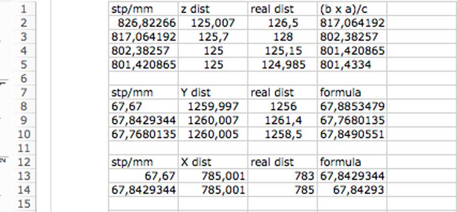
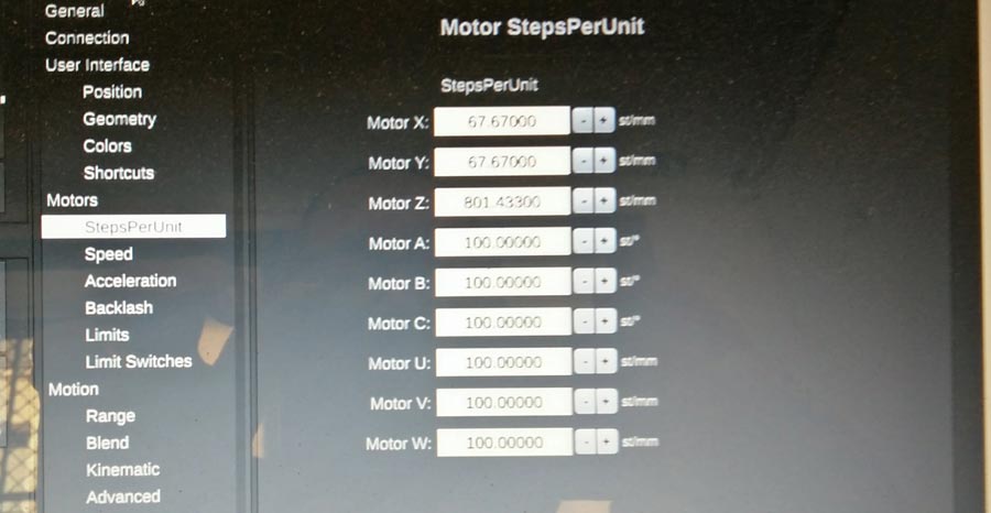
With these new settings I got a much better result but yet not perfect. I will need to do another calibration session for the machine to mill with 100% precision.
Conclusion
This week I learned a lot about designing, milling and make cam files. But the most importasnt thing I learn is about methiod and workflow: the secret is in taking time to do things properly. Most of the work is done in the preparation phase. Milling is what the machine does and the preparation is what the machine needs to know to do a good job. No point to go milling before 500% ready. It will only waist time, energy and material and create frustration. Making test is clue to get it right. I have learned also a lot by first using the shopbot and Rhinocam, and after contrasting the experience with Fusion360 and a smaller yet less intimidating machine. It helped me acquire a skills in term of planning design and milling stratyegy but also a much deeper understanding of the workflow, process and concpets of CNC.