TOTEM: a smoke signal machine
project development
In my free time, I like thinking of art installations for light festivals. Light is a fascinating material that attracks us in a mystical and instinctive way. But there is another natural fact that I think really intrigues us as much as light does: movement. Especially the movement of natural phenomena, such as burning fire, streaming water or running clouds, can also hypnotize us and have us inexplicably staring at them for a long time. Thinking how far we can control the movement of natural happenings is something that is lately obsessing me.
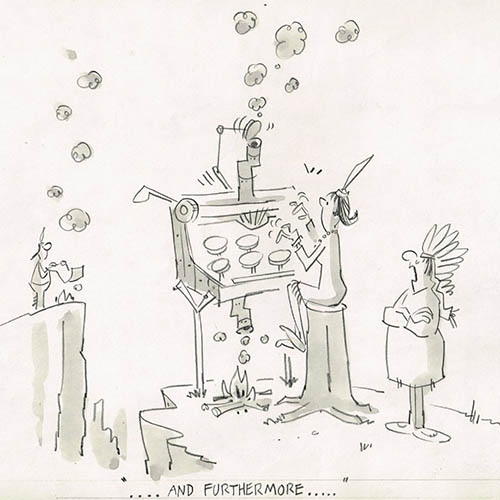
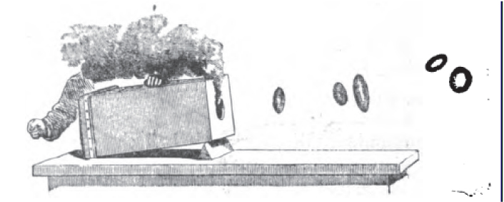
Smoke flowing is another captivating event and its always changing form is not easy to capture. However, thinking this way I remembered how Native American Indians somehow 'shaped' the smoke in order to make smoke signals as a relatively long-distant communication system.


Chinese (8c. BC)also used smoke signals


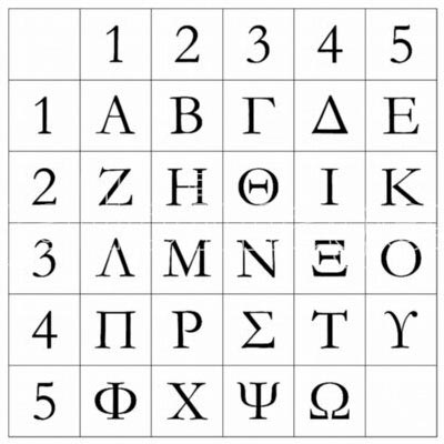
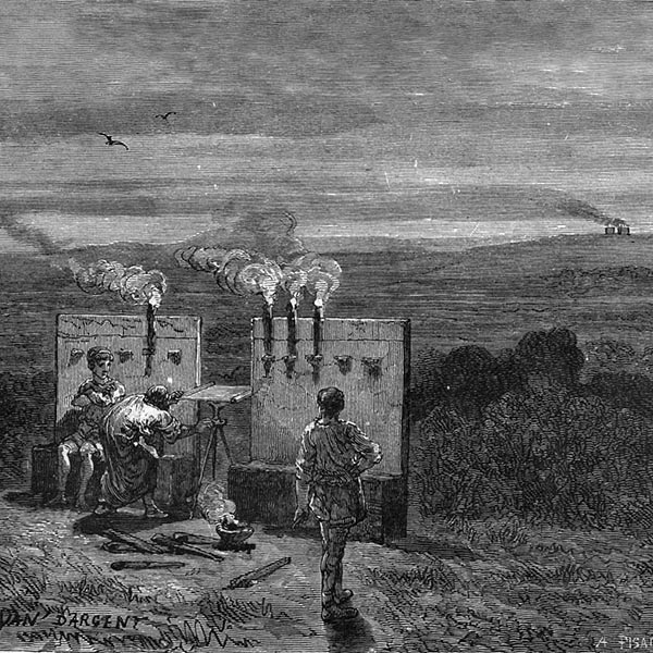
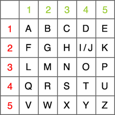
And also the Greeks (150 BC) used smoke signals. They used the Polybius square
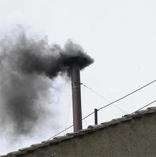
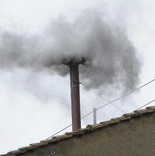
Nowadays smoke signals are not used anymore, except for symbolic acts like the choosing of a new Pope
I want to build a machine that can transform nowadays communication systems into smoke signals, mixing the oldest long-distant communication system with contemporary technology.
The signal
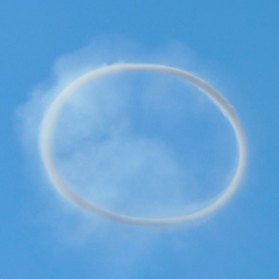
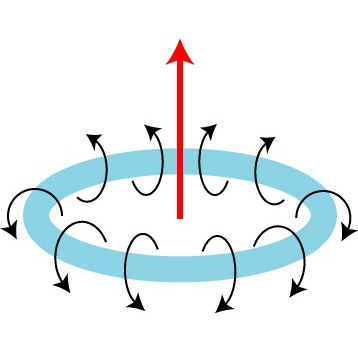
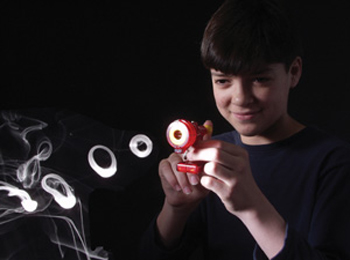
Since smoke form is hard to control, shaping it will be better for understanding the message. Smoke vortex rings can be helpful for that.
The language
In a morse language way (or on its own invented code), the smoke signal machine can shoot rings into the sky in order the be seen and read by people.

The machine
Similar things
the process
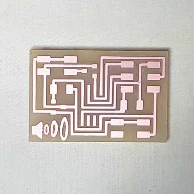
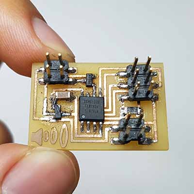
In week 11 - output devices I chose the speaker as my output device. But I'm not so interested in the sound but the movement of the speaker. This movement is what I will use to push out the smoke in the shape of smoke rings. I guess this movement can also be done with other methods (servos, steppers, solenoids...), but people who have done similar things before, they use a speaker, so I'm going to use the same thing for now...
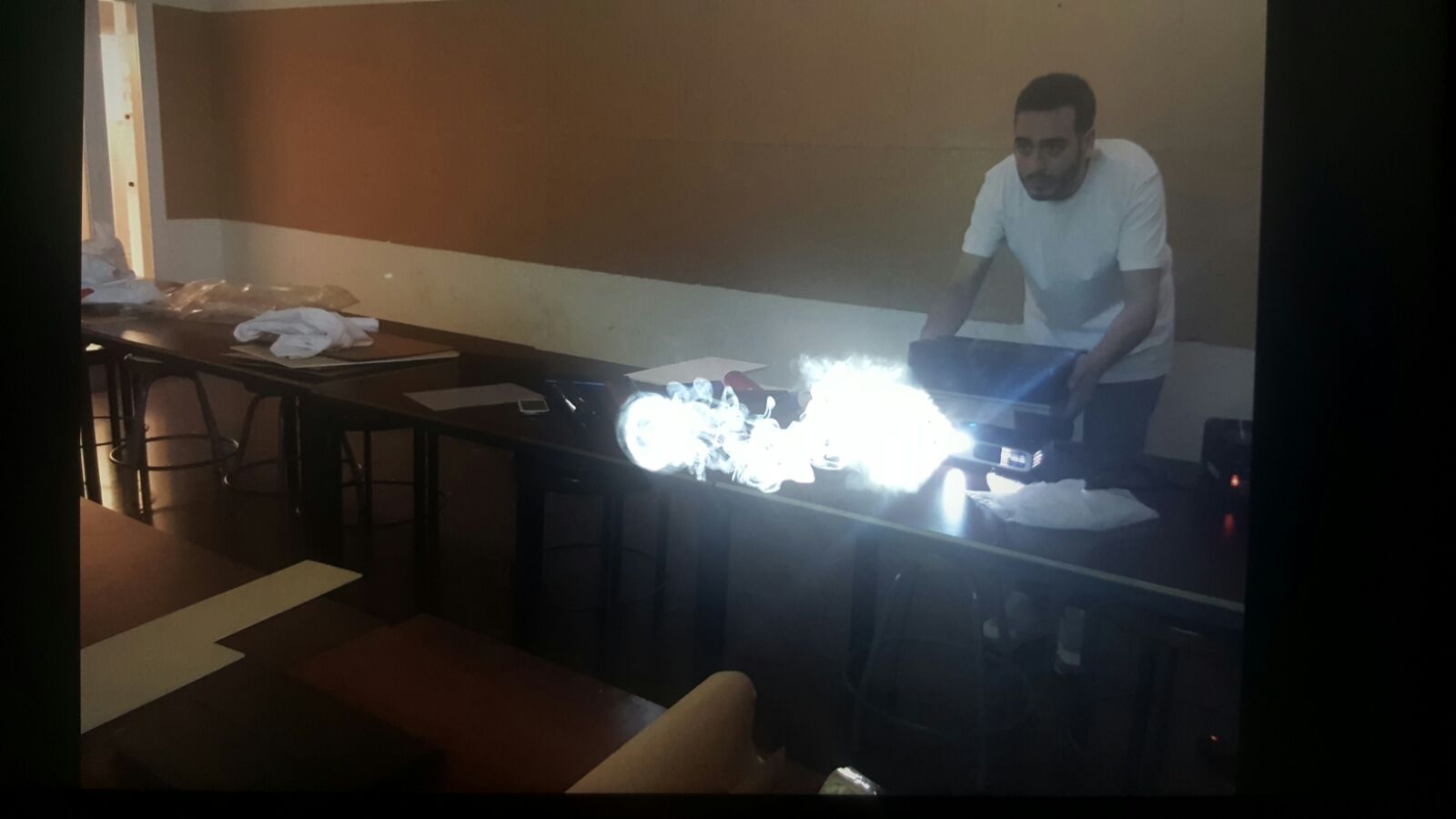
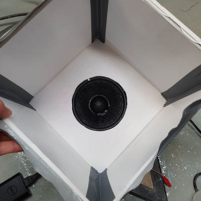
At the end of that week I did a first prototype of the smoke signal machine. I made a simple box made of foam board sealed with tape. On the bottom of it I made a hole for the speaker, and on the top I made a little hole through which the smoke rings would come out.
After trying different arduino examples online, I found a very simple code for generating the movement:
  #include < SoftwareSerial.h >
int speakerPin = 1;

SoftwareSerial myTotem(0, 2); // RX, TX

char val;

void setup() {
  pinMode(speakerPin, OUTPUT);
  myTotem.begin(9600);
  myTotem.println("Hello, world?");
}

void loop() {
  if (myTotem.available())
  {
    val = myTotem.read();

    if (val == '1')
    {
      analogWrite(speakerPin, 255);
      delay(20);
      analogWrite(speakerPin, 0);
      delay(20);
    }


  }
}
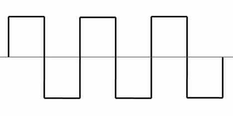
This code however generates the same movement strenght when the speaker moves up as when the speaker moves down. My idea was to get one beat for each smoke signal, which means I only want to hear the sound when the speaker goes up. In other words, right now this would be the movement of the speaker:
And this is what it should be, so the speaker goes up fast but it goes down slowly:
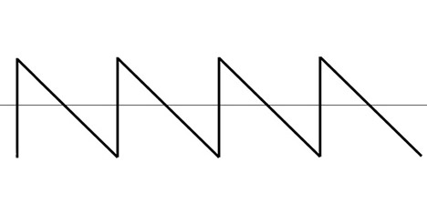
Thanks to Guillem, we managed to make it work with this code:
  int speakerPin = 1;

  void setup() {
    pinMode(speakerPin, OUTPUT);
  }

  void loop() {

    // fade in from min to max in increments of 5 points:
    for (int fadeValue = 0 ; fadeValue <= 255; fadeValue += 25) {
      // sets the value (range from 0 to 255):
      analogWrite(speakerPin, fadeValue);
      // wait for 30 milliseconds to see the dimming effect
      delayMicroseconds(30);
    }


     delayMicroseconds(50);


    // fade out from max to min in increments of 5 points:
    for (int fadeValue = 255 ; fadeValue >= 0; fadeValue -= 5) {
      // sets the value (range from 0 to 255):
      analogWrite(speakerPin, fadeValue);
      // wait for 30 milliseconds to see the dimming effect
      delayMicroseconds(10);
    }
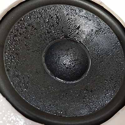
Because the smoke is made of glycerine and water (actually I should call it fog) there is some condensation. I'm still not sure how I will solve this, or if this can end up affecting the speaker.
At that stage, I started to think about having different sizes of holes in order to make different sizes of rings, and therefore being able to make a binary code such as morse in order to send complex messages. I thought of the idea of making some kind of rotating template with different hole sizes. But my fab mate Oscar suggested something very interesting: using an iris/diaphragm. I decided to develop this idea later on the week 14&15 - mechanical & machine design.
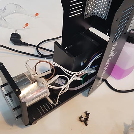
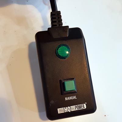
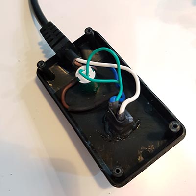
In this first prototype, I filled the box with smoke manually but I would like to include the smoke machine mechanism inside my machine. For that I dismantled the fog machine in order to understand its components and include them in my machine. The fog machine has a manual controller, which I would also like to control by installing a relay.
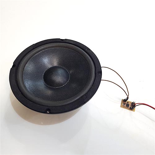
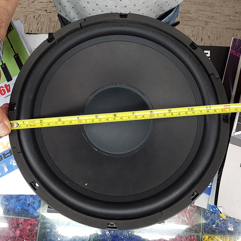
Then I decided to design the bigger version. I first bought a bigger woofer.I went to Metro Electronica a told them what I wanted the speaker for. They told me they have a client who bought this Beyma 12BR70 12" low frequency speaker for experimenting with non-newtonian fluids. I was not sure if this was the one for me, but I went for it anyway.
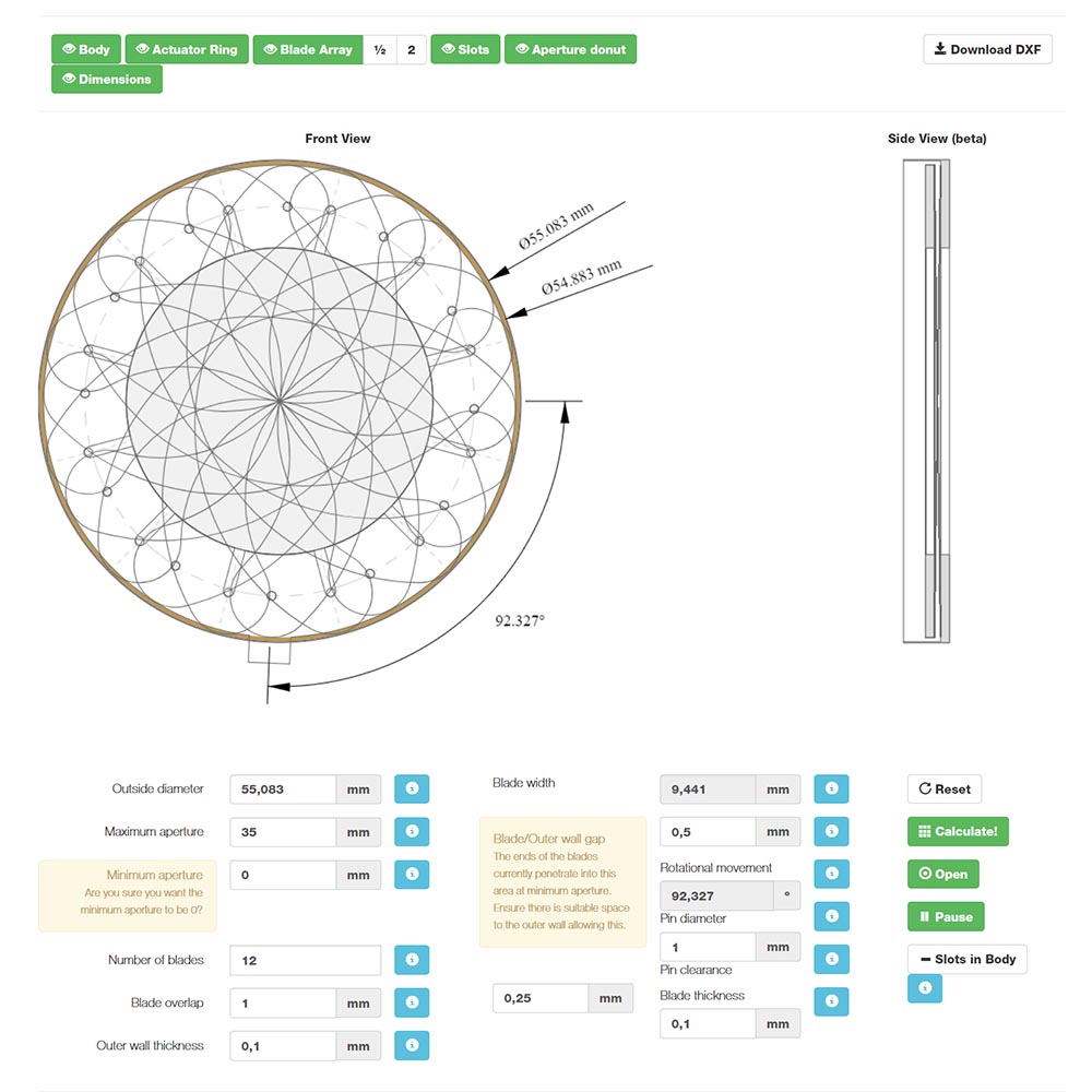
To design the iris I used the Iris Calculator, which I already used for the week 14&15 - mechanical & machine design. I didn't follow any rule for the relation of the iris size and the woofer size, I completely did things by intuition. So considering I had a 12" (≈30cm) woofer, I chose an iris with a maximum aperture of 35cm and 12 blades. The more number of blades, the thinner the blades will be, which also means a thinner frame.
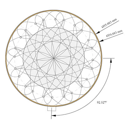
I noticed something very particular when I was playing with the iris calculator. When the blades are overlapped it really looks like a dreamcatcher, another sacred indian item. Dreamcatchers were traditionally used by the Ojibwe nation as talismans to comfort the sleeper below, "filtering" the air filled with good and bad dreams, catching up bad dreams and only letting good dreams pass through. Somehow the iris will act the same way, a filter retaining the air filled with smoke and only letting the message pass through.

Totem poles are monumental carvings consisting of poles carved with symbols or figures. They are usually made from large trees by some tribes of native american indians. Each animal or spirit carved on the pole has meaning, and when combined on the pole in sequence, each figure is an important symbol constituent of a story or myth.

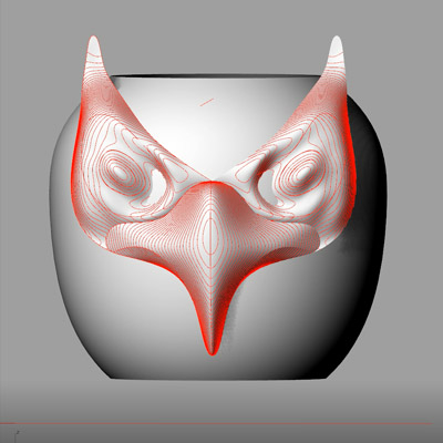
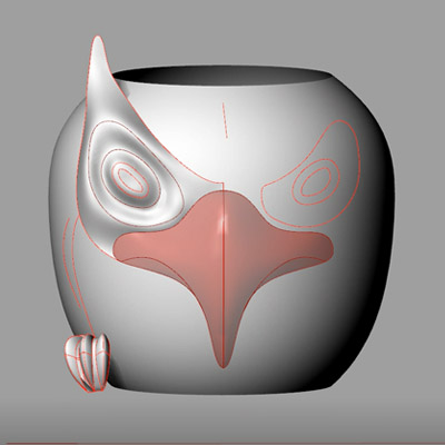
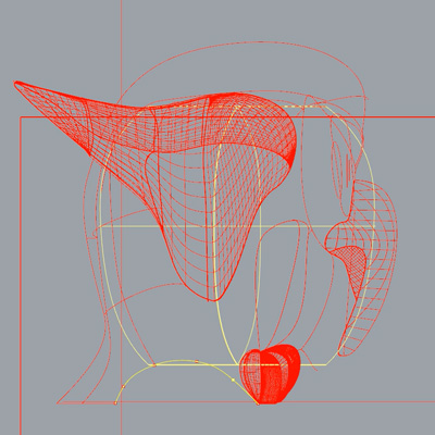
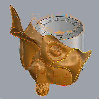
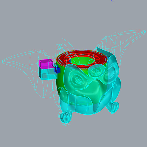
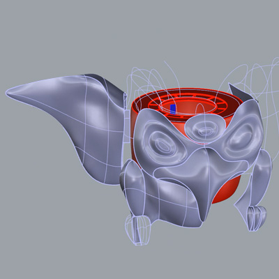
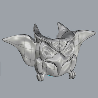
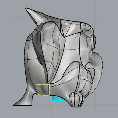
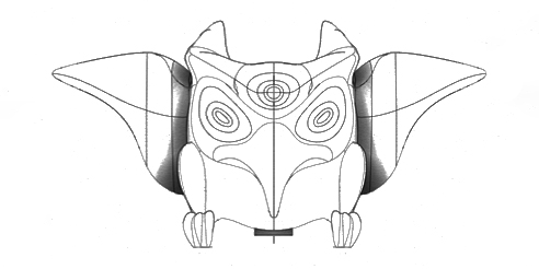
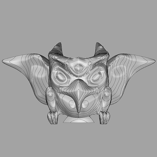
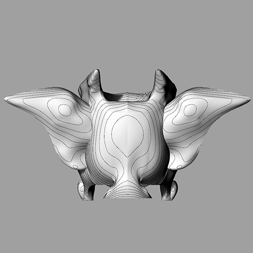
The thunderbird was the symbol of power in the sky. He controlled the thunder and lighting. He is usally at the top of the totem pole. His wings are always out-stretched. He was a messenger from the sky. Because TOTEM will send messages into the sky in the shapes of smoke signals, I decided to extract the symbolism of the thunderbird and apply it in my design. However, modelling the thunderbird is tricky. The creature is a mixture of eagle and owl. In order to model it nicely I took some inspiration from pictures of real birds. The beak, the legs, the wings, the ear tufts...
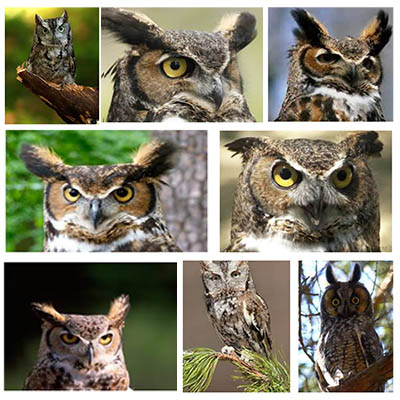
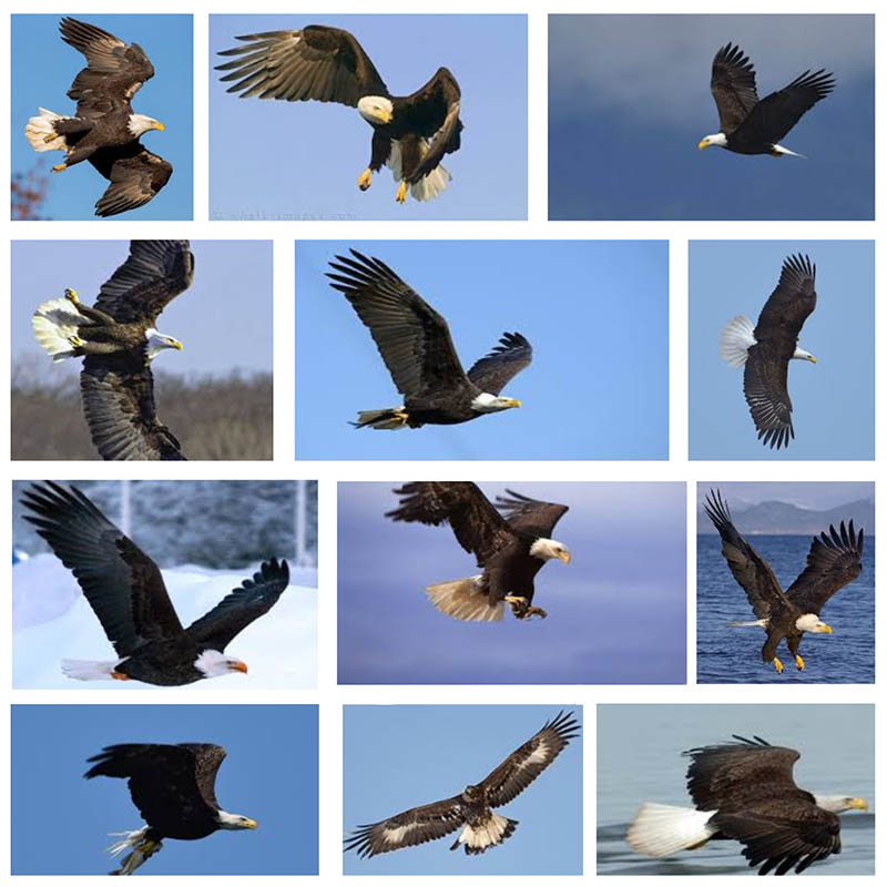

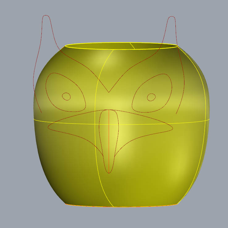
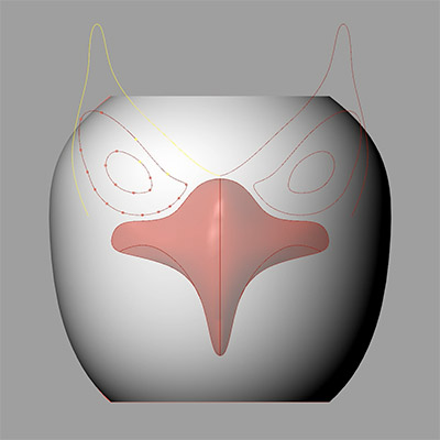
I have never 3d modeled an organic shape with such a level of detail, and everything is tricky and easy to look bad if I don't do it with care. I'm not looking for a realistic appearance (totems weren't either realistic) but neither do I want it to look like a parody of a bird or character out of an Angry Birds game, so the design should be something in between.
I modeled some parts directly in Rhino and some other parts in Grasshopper. I realized the patch command in Rhino and the Patch command in Grasshopper do not work exactly the same way. The one in Grasshopper seems to be more accurate with what I wanted most of the times, so that's why I mixed both solutions.
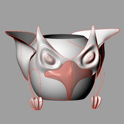
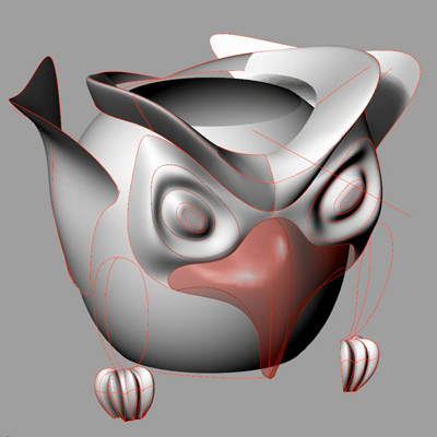
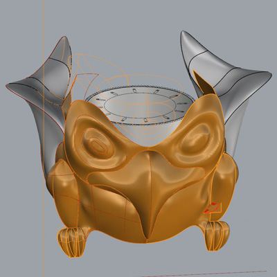
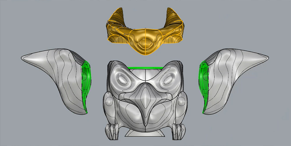
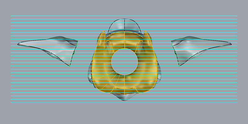
At the beginning I thought of having all the machinery at the back of the bird. However, due to the size of all the components, it turned quite complicate to fit everything there, especially the smoke machinery. When I modeled the wings, I did them mostly flat and attached to the body of the bird. I then decided to change the location of all the machinery to the wings, which would be spread open, just like totems. For assembling everything and machinery maintenance, having removable wings will be very helpful.
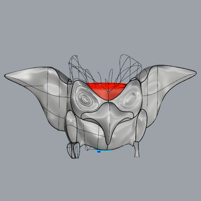
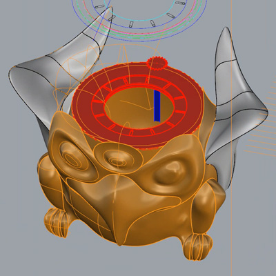
At the top of the head there is another removable piece that covers the whole iris mechanism. This Mohican hairstyle piece is inspired in the ear tufts on owls. This removable piece will also be very helpful for assembling the iris and check any possible problem in the mechanism.
The bottom of the bird is for the speaker/woofer. Because I'm afraid the woofer can get warm, I will leave some air underneath the TOTEM. The claws and tail of the thunderbird will elevate the volume from the ground so the speaker can breathe better. This might help evacuate the exceeding condensed fog, in case there is any.
I chose a 12" (30.48cm) woofer, but I made the space big enough to fit a 15" (38.1cm) woofer just in case. I found out there is a type of speaker which could also be interesting to try, a coaxial speaker. As far as I understood it's like a speaker in the center of a woofer, so it can reproduce a wider range of frequencies, which means I could play music and push the smoke at the same time with only one speaker. I will not try it now because they are very expensive though…but in the future…
Totems used to have very particular motives (haida style) painted on them.


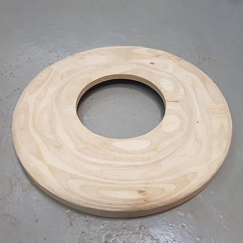
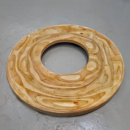
Since I will mill my design in plywood, I can end up having some tribal motives aswell just by the nature of the material itself: the milling will reveal the different layers of plywood, something similar to the images below.
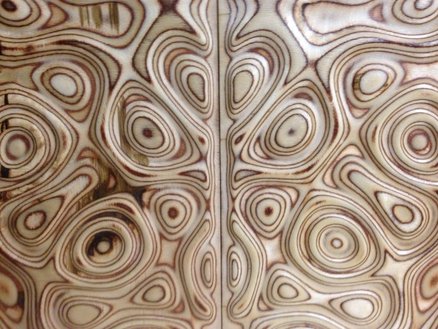
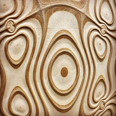
The wood I would like to use is a combi plywood which mixes two kind of woods. Because one is dark and the other is lighter, a very visible curvy pattern will appear when milling it (hopefully). I found this one (left), which alternates layers of okoume/poplar but it comes from France and it would take a few days to arrive here. The closest thing I could find near Barcelona is this one (right), which is similar but not the same, because the okoume is just on the outside layers and the interior are only poplar layers.
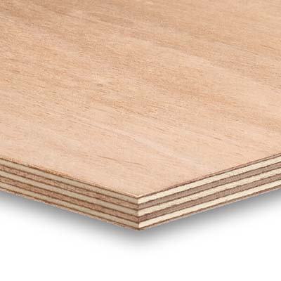
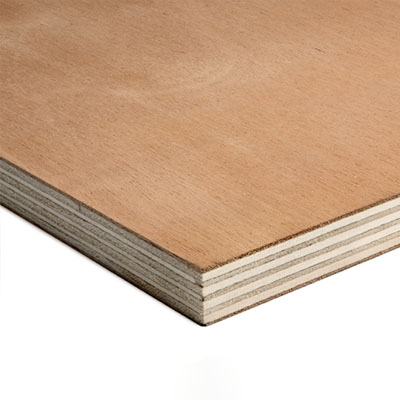
Since I don't have many days left, I will go for the one on the right. Hopefully I will still be able to see the pattern I'm looking for...
These are the lines I expect to see on TOTEM:
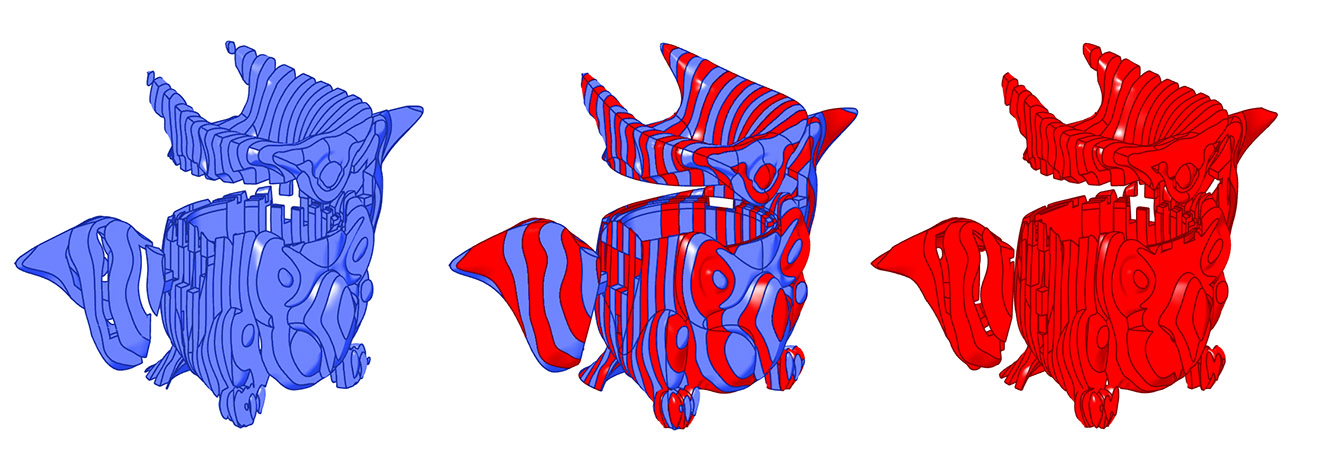
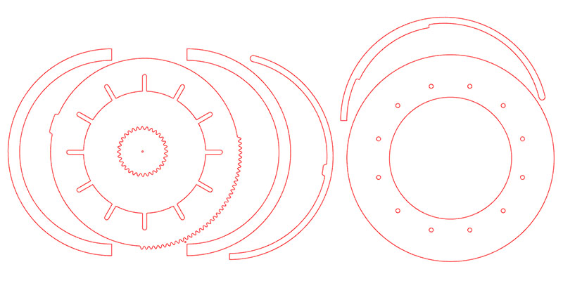
I split the whole model in slices of 30mm thick, which will be the pieces for milling. I created several planes with a 30mm offset and trimmed the model. That way I had the edge face of every piece.
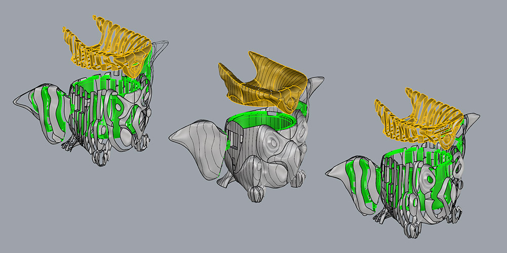
For the two flat faces of every piece, I intersected the planes with the model. That way I can have an outer boundary of every piece flat faces (I discovered later this could have been done with the command Contour). Since the 3d model is not 100% perfect, this boundaries were not fully closed curves, so surfaces could not be made. With the help of CrvEnd (shows the end of curves) I closed every curve with BlendCrv (+join).
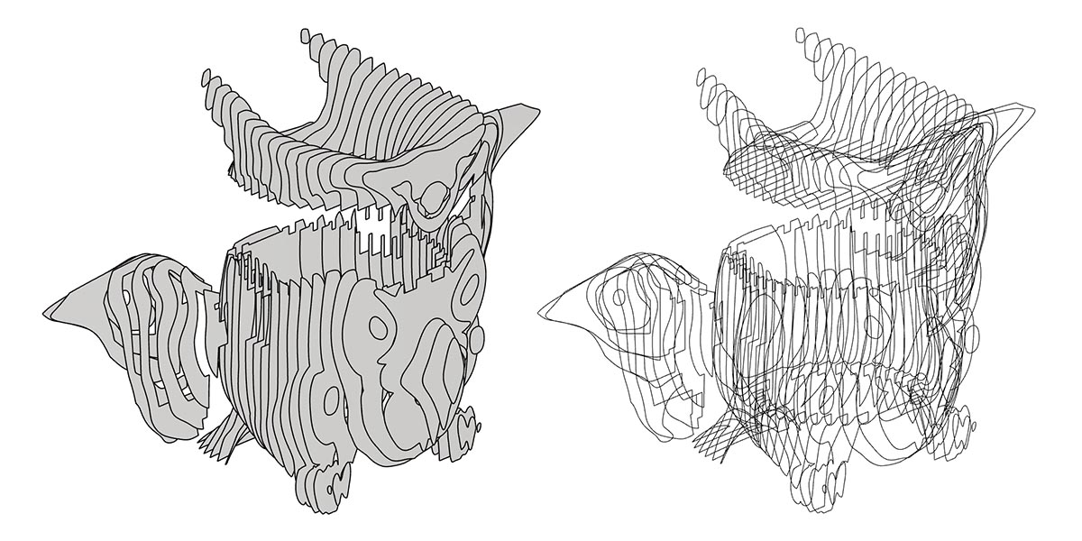
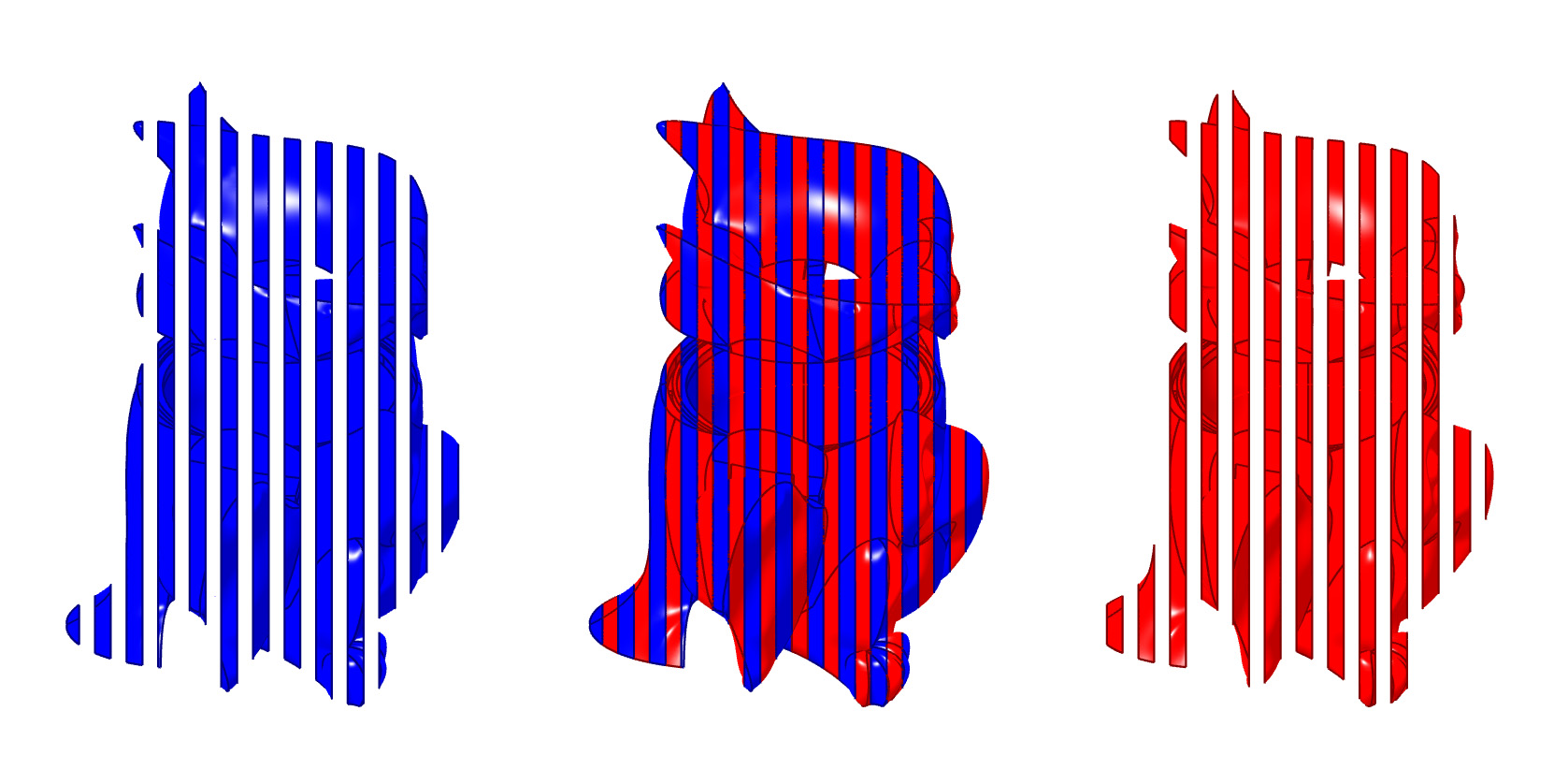
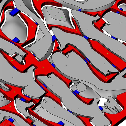
Since I had now the flat face and the edge of every piece, I had all the pieces that form the whole 3d model. I separated them into even and odd (red/blue) for more clarity, since each piece shares a face with the piece next to it.
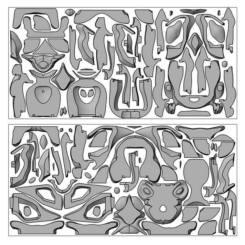
I did all the nesting piece by piece until fitting everything in the two sets of wood. It took some time and pieces had to be very close together in order to fit in two wood stocks.
Update: For the nesting I could have used the help of RhinoCAM or SVGnest, but I believe it can only do the nest with 2d pieces, so first you need to have the outline of every piece. To obtain these outlines, you can use the Dupborder command. If the result is not the desired one, you can turn the polysurfaced objects into a meshes (command Mesh) and get the outline with the command Meshoutline. (Ungroup>Join>Mesh>Meshoutline>Rebuild). That way you can obtain the 'footprint' of every 3d piece in 2d, so the automatic nesting can be calculated.
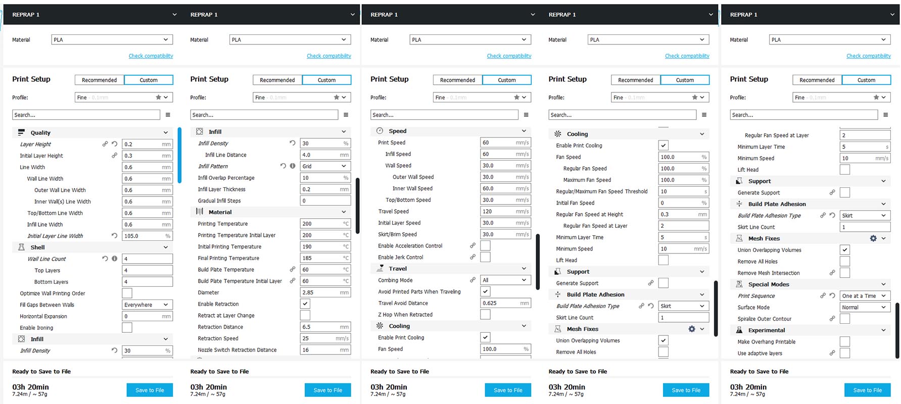
The strategy to follow in RhinoCAM for milling these 3d pieces is Horizontal Roughing + Parallel Finishing. However something else needs to be done in order to save some time. From each piece, we need to make some offset outer boundary curves (in this case 12mm) that will serve to contain the cutting to only the areas needed. That way we will not mill the areas not needed (red) and save some time. In addition, I made some tabs (blue) that extend from the wanted parts to the containment curves. These tabs will help fixture the parts to the stock on the bed of the CNC machine. Also some marks were done for an easier assembling of the pieces (grey points) and for the screws (green points). A very thin floor is also necessary for the machine to detect the pieces.
I had everything ready for milling the thunderbird...but little I knew this was not going to happen. Two 2500x1250 boards to be 3d milled on both sides....and RhinoCAM estimated a milling time of about 3 or 4 days... when I only had 5 days left for the final project presentation.
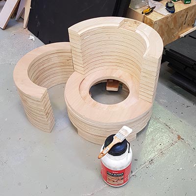
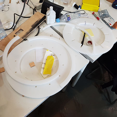
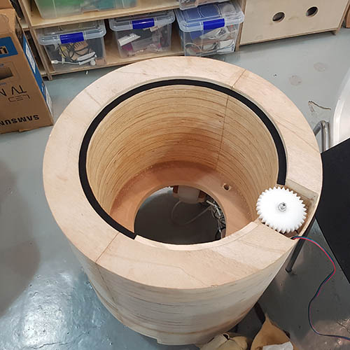
Ok, that means no thunderbird... I took me a while to accept this, but there is no way TOTEM will not be ready for the final presentation day. So I went for Plan B. I opened back Rhino again and modeled a simpler TOTEM with the same wood I had: just a cilinder made of sections. It's uglier than the thunderbird and it doesn't have a face to look at but it will do the job.
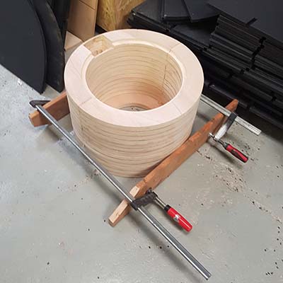
After milling the pieces, I glued them all together using wood glue and some clamps.
Even though I simplified the pieces, I still wanted to see pattern of layers that appears when the plywood is 3d milled. That's why I milled the cover of the machine with a wavy relief. The resulted cover is the one on the left. I photoshopped the picture to imagine how it would look if it was varnished, in order to make the contrast of layers more clear. It looks quite trippy...
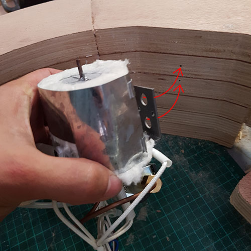
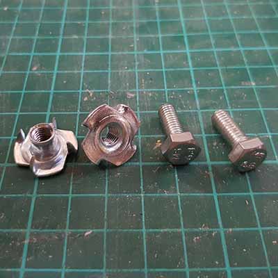
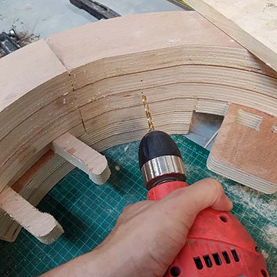
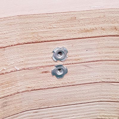
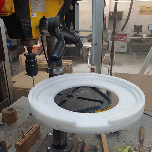
Time to set up all the fog machinery underneath. For the heater, I needed to make a couple of drills and install two T-nuts on the wood.
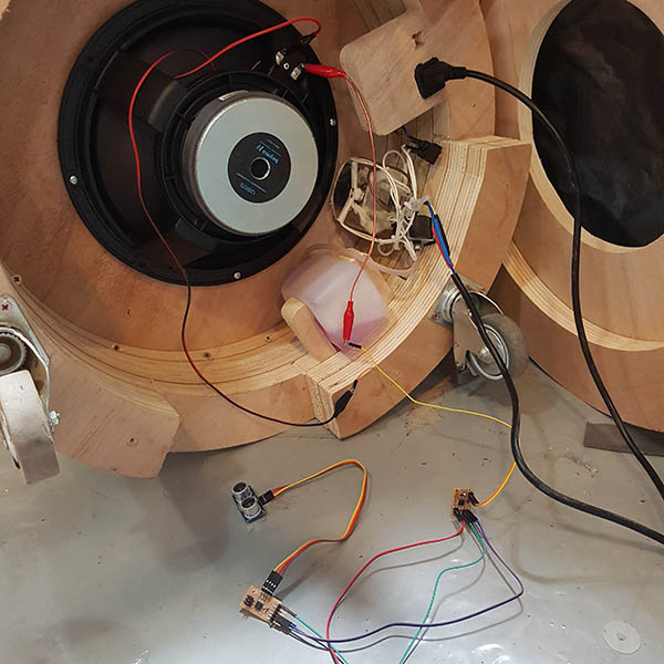
The rest of the components were already considered in the design in order to press-fit them. The speaker was installed in place using a few screws.
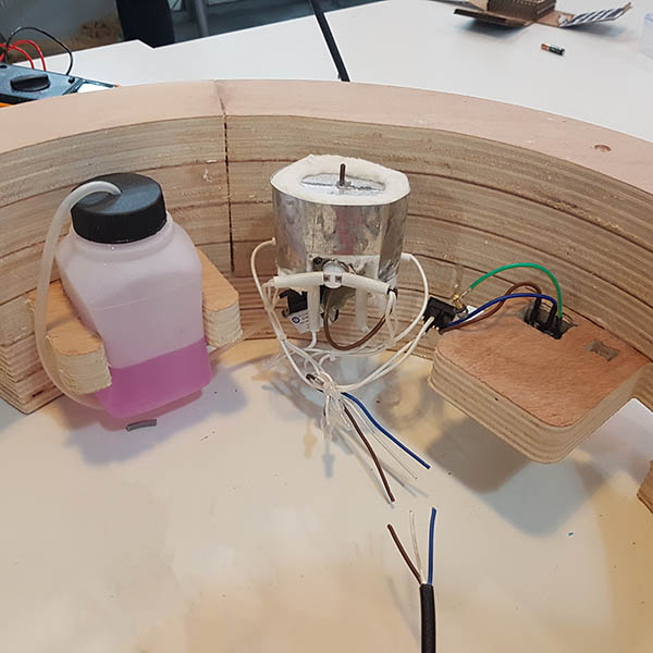
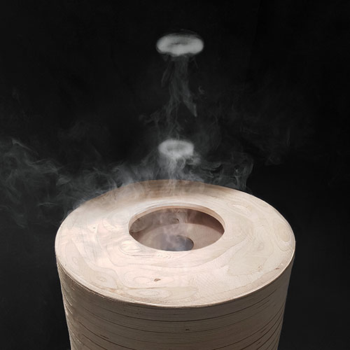
The iris mechanism was not ready for the final presentation day, so I laser cuttered a temporary cover with a fixed diameter. The fog mechanism was incorporated in the bottom of TOTEM, but the fog actuator was finally not connected to a relay, so the fog was activated manually. Finally, here is the machine making smoke signals automatically.
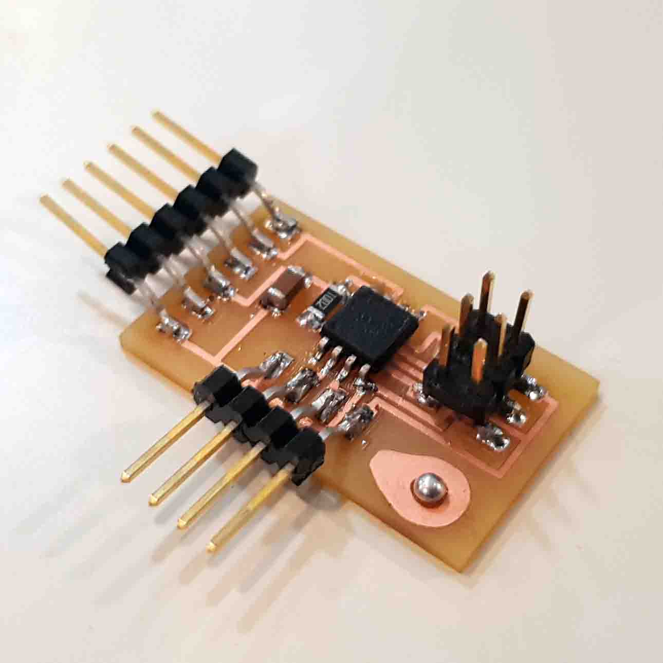
Even though my final goal is synchronizing TOTEM to music (which I will do later using an Arduino shield), for the final presentation I decided to use a distance sensor (sonar) as an input device, like I did in week 10 - input devices. I communicated both the speaker board and the sonar board via serial communication, as seen in week 13 - networking & communications.
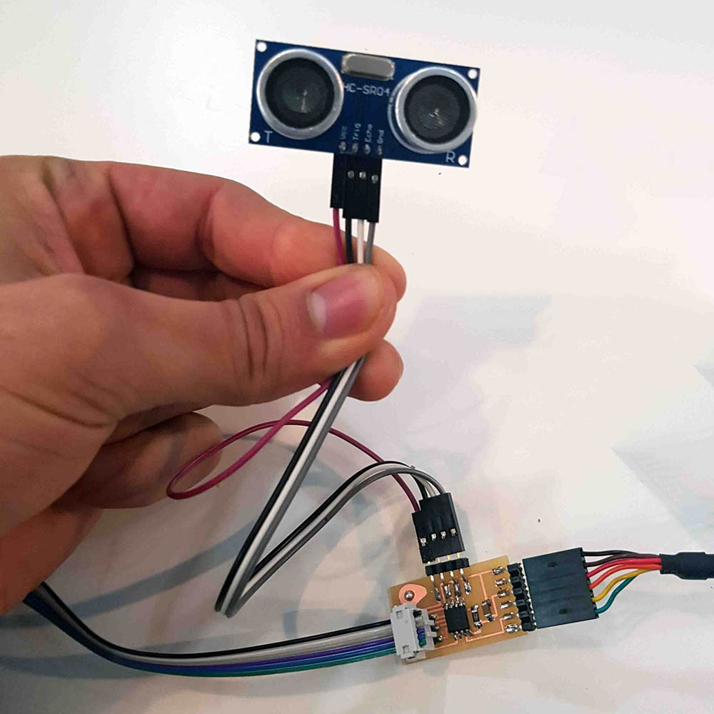
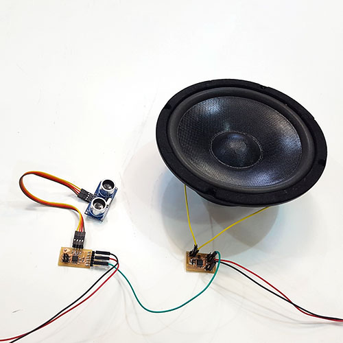
And here is the result of TOTEM working with the distance sensor
Basically I wanted the speaker to make a push everytime my hand gets close to the sonar. It was tricky to achieve one single push for every time I got my hand close to the sonar. After several tries, I solved it like this:
    #include < SoftwareSerial.h >

    SoftwareSerial mySonar(1, 2); // RX, TX

    const int Trigger = 4;//Pin digital 4 para el Trigger del sensor
    const int Echo = 3;   //Pin digital 3 para el Echo del sensor
    int i = 0;

    void setup() {

      pinMode(Trigger, OUTPUT); //pin como salida
      pinMode(Echo, INPUT);  //pin como entrada
      digitalWrite(Trigger, LOW);//Inicializamos el pin con 0

      mySonar.begin(9600);
      mySonar.println("Hello, world?");

    }

    void loop()
    {

      long t; //timepo que demora en llegar el eco
      long d; //distancia en centimetros

      digitalWrite(Trigger, HIGH);
      delayMicroseconds(10);          //Enviamos un pulso de 10us
      digitalWrite(Trigger, LOW);

      t = pulseIn(Echo, HIGH); //obtenemos el ancho del pulso
      d = t / 59;    //escalamos el tiempo a una distancia en cm

      if ((d < 10) && (i == 0)) {
        mySonar.write('1');
        mySonar.println();
        mySonar.println("boom");
        i = 1;
          }

      if ((d < 10) && (i >= 1)) {
        mySonar.write('2');
        mySonar.println();
        mySonar.println("move away");
        i = 2;
          }

      else {
        mySonar.write('2');
        mySonar.println();
        i = 0 ;
      }

    }
    #include < SoftwareSerial.h >
    int speakerPin = 1;

    SoftwareSerial myTotem(0, 2); // RX, TX

    char val;

    void setup() {
      pinMode(speakerPin, OUTPUT);
      myTotem.begin(9600);
      myTotem.println("Hello, world?");
    }

    void loop() {
      if (myTotem.available())
      {
        val = myTotem.read();

        if (val == '1')
        {
          analogWrite(speakerPin, 255);  // S
          delay(20);
          analogWrite(speakerPin, 0);
          delay(20);
        }
      }
    }
The code for the sonar board is basically the same as the one I used for week 10 (input devices), but adding the Serial Communication lines seen in week 12 (network & communication), and adding some statements. I'm sure these statements could be better written, but considering my no background in coding, I'm quite happy that I made it work.
Basically I defined a variable:
int i = 0;
Inside the loop(), if the distance read by the sonar is more than 10cm, the variable will remain the same, i=0. But if we get our hand closer to the sensor, as soon as the read distance gets less than 10cm, this variable will now be i=1 and the sonar board will send a '1' via serial, which will be read by the speaker board and make one speaker push.
    if ((d < 10) && (i == 0)) {
      mySonar.write('1');
      mySonar.println();
      mySonar.println("boom");
      i = 1;
        }
If the distance detected by the sonar is still below 10cm, on the next loops the variable will be now i=2 and the sonar board will now send a '2' via serial, which doesn't mean anything to the speaker board, so the speaker will not do anything.
    if ((d < 10) && (i >= 1)) {
      mySonar.write('2');
      mySonar.println();
      mySonar.println("move away");
      i = 2;
        }
In order to get another push, we need the variable to be i=0 again, which we will only achieve by making the distance read by the sonar higher than 10cm.
    else {
      mySonar.write('2');
      mySonar.println();
      i = 0 ;
That way when the variable is i=0 and the distance detected by the sonar gets lower than 10cm again, the sonar board will send another '1' via serial, which will be read by the speaker board and make another speaker push.
But the smoke signals were not so big and not as clear as I wanted. Some smoke was leaking through many gaps in the wood.
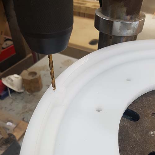
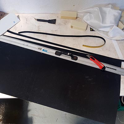
I decided to keep on working on the machine and develope the iris. The iris is made of HDPE, a high density polyethylene. The good thing about this material is that friction is not so high, allowing smoother movements in machinery. When I did the iris for the machine week I used wood and friction sometimes got the iris stuck. By using HDPE I tried to get a better mechanism movement. I used a Polyethylene adhesive to glue all the pieces together (hot glue or any other kind of glue will not stick well to the material). Also I made a few holes by hand for the screws that will hold everything together (iris rings, blades and pins, cover).
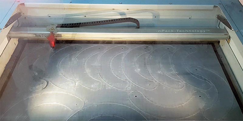
I cut the blades of the iris with the lasercutter. The material is 0.5mm "plakene", which is a commercial name for a kind of polypropylene (PP). This material can be lasered as it doesn't contain clorine derivated substances and doesn't release toxic gases when lasered.
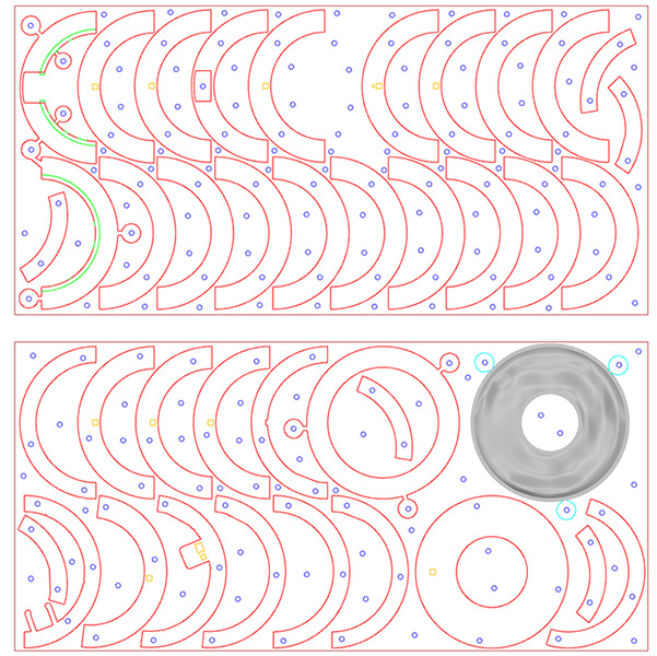
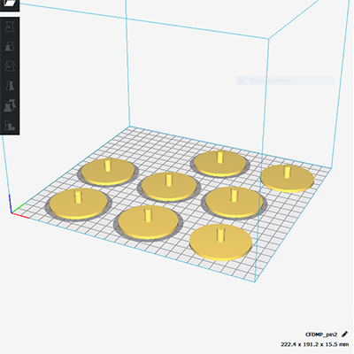
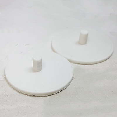
To hold the blades to the actuator rings, I 3Dprinted some pins. However I didn't expect they would not work. What happens is, as seen in the picture below, when the iris is closed, the overlapping of the green blade and blue blade is bigger than the pin head diameter (magenta). That means the blades can close but they can't open back again. Two options I had for solving this: gluing headless pins to the blades (like I did for the machine design week) or making the head of the pins bigger than the overlapping (cyan).

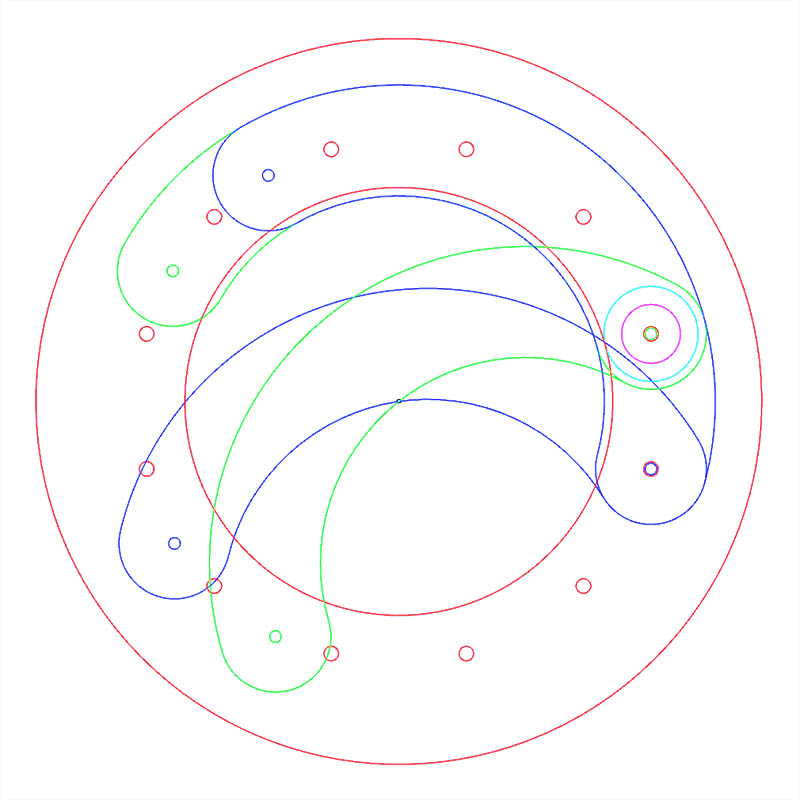
I decided to go for the second option.
In order to make the dreamcatcher appearance more clear, I chose a semitransparent polypropylene (PP) for the blades because you can kind of see through them, which helps to see the overlapping of the blades and therefore, the dreamcatcher look.
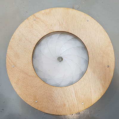
I put some rubber on the iris cover stand so it seals better the volume containing the smoke. (the tape is to seal the pin holes, so less smoke will leak throuh)
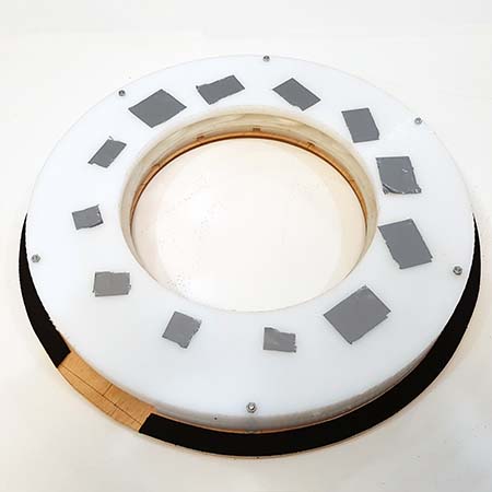
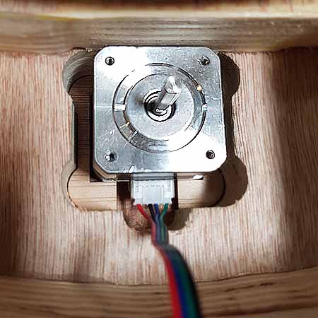
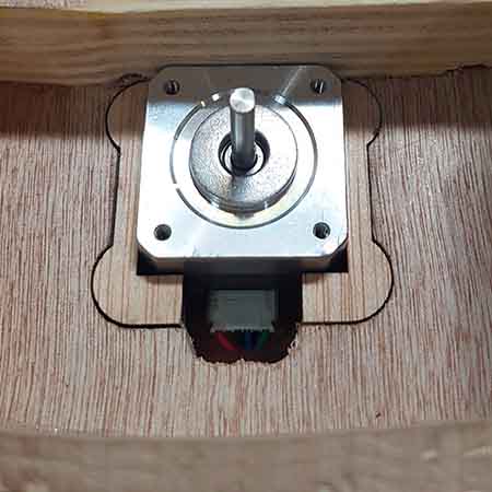
Here is the iris finally working using my hand. Now I just have to replace my hand with a stepper motor.
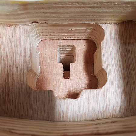
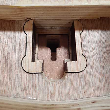
I made a mistake when doing the milling strategy: I made a profile cutting for the stepper motor hole, but I made it an exterior profile cutting instead of a interior profile cutting. That means the resulted hole for the stepper ended up being bigger than it should have been. I solved this by cutting the difference with the laser cutter.
  #define EN        8
  //Direction pin
  #define X_DIR     5
  //Step pin
  #define X_STP     2
  //DRV8825
  int delayTime=5000; //Delay between each pause (uS)
  int steps=190;// Steps to move

  void move(boolean dir, byte dirPin, byte stepperPin, int steps)
  {
    digitalWrite(dirPin, dir);
    delay(100);
    for (int i = 0; i < steps; i++) {
      digitalWrite(stepperPin, HIGH);
      delayMicroseconds(delayTime);
      digitalWrite(stepperPin, LOW);
      delayMicroseconds(delayTime);
    }
  }

  void setup(){
    pinMode(X_DIR, OUTPUT); pinMode(X_STP, OUTPUT);
    pinMode(EN, OUTPUT);
    digitalWrite(EN, LOW);
  }

  void loop(){
    move(false, X_DIR, X_STP, steps); //X, Clockwise
    delay(1000);
    move(true, X_DIR, X_STP, steps); //X, Counterclockwise
    delay(1000);
    }
Just like totems were worshiped by native americans, I want people to dance to TOTEM. TOTEM will react to sound and synchronize smoke signals to the beat of music.

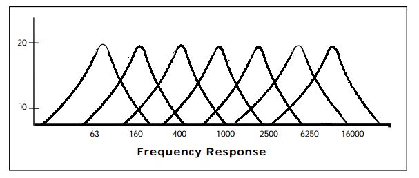
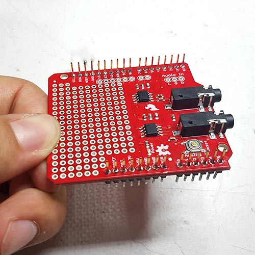
To achieve that, I used the Spectrum Shield, which enables Arduino with the capability of splitting a stereo audio input into 7-bands per channel. You can then read the amplitude of each channel using the ADC on your Arduino allowing you to control everything from LEDs to motors, pumps to relays, or even fire, all with sound.
This guide was very helpful to understand how the shield works. Out of the 7 bands the audio signal is split into, I will take the lower frequency one (63Hz), so I can synchronize the bass of electronic music to the smoke signals.
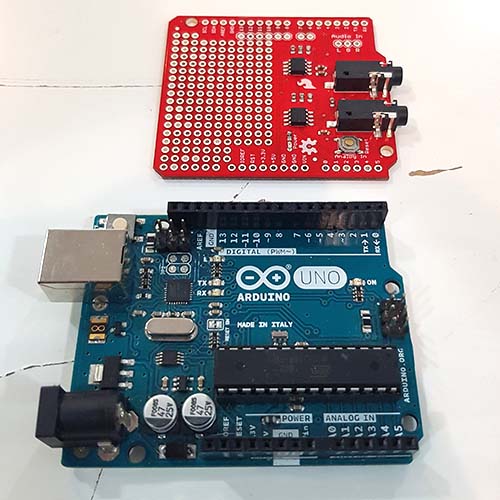
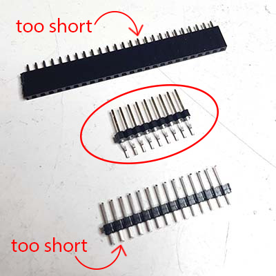
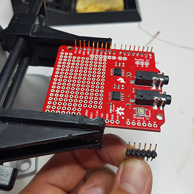
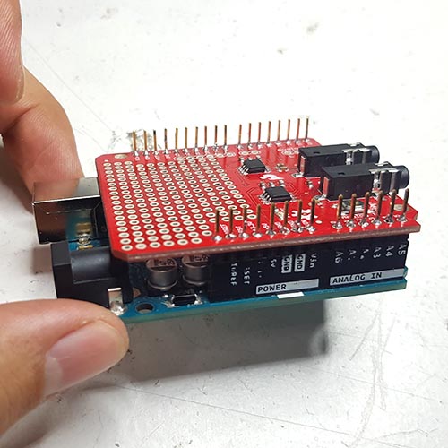
This shield uses the Arduino Uno R3 footprint, but it's a header-less shield, so it doesn't have a connection method to Arduino. We need to turn it into a fully functional, ready-to-plug-in module. Usually we would do it with stackable headers, but we don't have them in the lab so I will use a male to male pitch horizontal header (straighten with the help of pliers). The other options have very short pins and will not work properly.
Once straighten, I soldered them to the shield. Useful instructions about this can be found here
However, when I got into programming the board. I realized the board doesn't detect peaks in the audio. To solve this I applied the same method I did for the distance sensor, I generated a variable
j = j + 1;
and chose a threshold of 250.
if ((Frequencies_One[0] > 250) && (j == 1)) {
  myBoom.write('1');
}

if (Frequencies_One[0] < 250) {
  j = 0;
}
This means when the read frequency is below 250, our variable will remain j=0. But when the sound gets higher than 250, this variable will start growing each time the loop is run (j=1, j=2, j=3, j=4, j=5, j=6...) and will go back to j=0 when the sound gets below 250 again. It's in the moment of the sound exceeding the threshold when our variable will be j=1 and therefore it will write ('1') via serial. By this method we can somehow detect a peak, as long as the sound gets above and below our threshold. However, for instance, if there are two consecutive peaks above our threshold, it will only detect it as one.
Here is the entire code I used for the Arduino:
  #include < SoftwareSerial.h >

  SoftwareSerial myBoom(0, 1); // RX, TX

  //Declare Spectrum Shield pin connections
  #define STROBE 4
  #define RESET 5
  #define DC_One A0
  #define DC_Two A1


  //Define LED connections on the Arduino/Shield
  int LED[] = {7, 8, 9, 10, 11, 12, 13};

  //Define spectrum variables
  int freq_amp;
  int Frequencies_One[7];
  int Frequencies_Two[7];
  int i;
  int j = 0;

  /********************Setup Loop*************************/
  void setup() {
    //Set LED pin configurations
    for (i = 0; i < 7; i++)
    {
      pinMode(LED[i], OUTPUT);
      digitalWrite(LED[i], LOW);
    }

    //Set spectrum Shield pin configurations
    pinMode(STROBE, OUTPUT);
    pinMode(RESET, OUTPUT);
    pinMode(DC_One, INPUT);
    pinMode(DC_Two, INPUT);
    digitalWrite(STROBE, HIGH);
    digitalWrite(RESET, HIGH);
    pinMode(3, OUTPUT);

    //Initialize Spectrum Analyzers
    digitalWrite(STROBE, LOW);
    delay(1);
    digitalWrite(RESET, HIGH);
    delay(1);
    digitalWrite(STROBE, HIGH);
    delay(1);
    digitalWrite(STROBE, LOW);
    delay(1);
    digitalWrite(RESET, LOW);

    myBoom.begin(9600);
    myBoom.println("Hello, world?");
  }


  /**************************Main Function Loop*****************************/
  void loop() {

    Read_Frequencies();
    Graph_Frequencies();
    delay(50);

  }


  /*******************Pull frquencies from Spectrum Shield********************/
  void Read_Frequencies() {
    //Read frequencies for each band
    for (freq_amp = 0; freq_amp < 7; freq_amp++)
    {
      Frequencies_One[freq_amp] = analogRead(DC_One);
      Frequencies_Two[freq_amp] = analogRead(DC_Two);
      digitalWrite(STROBE, HIGH);
      digitalWrite(STROBE, LOW);
    }
  }

  /***************Light LEDs based on frequencies******************/
  void Graph_Frequencies() {

    j = j + 1;

    if ((Frequencies_One[0] > 250) && (j == 1)) {
      myBoom.write('1');
    }

    if (Frequencies_One[0] < 250) {
      j = 0;
    }


  }
And here is the result of TOTEM synchronized to the beat of music:
TOTEM can only make small smoke rings yet. The movement of the woofer is still not big enough to push out big rings. I would need to try to connect the woofer to an amplifier to increase the movement. Another option could be reducing the volume containing the smoke, so the ratio WooferSize/SmokeVolume is bigger. If still this is not enough, instead of using a woofer I would try a different mechanism to push out the smoke.
Also, the machine is still not 100% airtight, air and smoke leaks through the gap between the iris rings and the blades.
Another consideration is the kind of smoke. This fog is made of glycerine and water. Technically the more glycerine, the denser the fog (I would consider trying the vaping liquid used in electronic cigarretes). Another smoke could be the evaporation of solid CO2 (aka 'dry ice'), which is denser than air. That means it will tend to descent, so the air will not become cloudy and the smoke rings will be much more clear.
TOTEM is still not a final product. Many improvements need to be done yet. Hopefully I can keep working on this idea. My main idea for TOTEM is to become a Live Show machine that can be accompanied by a DJ playing some good bass elecronic music, and a VJ who would control the smoke rings, as well as a projection mapping on the bird:

Hopefully this becomes true someday!
download files

This work is licensed under a Creative Commons Attribution-NonCommercial-ShareAlike 4.0 International License.