week 3 - computer-controlled cutting
-group assignment: characterize your lasercutter, making test part(s) that vary cutting settings and dimensions
-individual assignment: design, lasercut, and document a parametric press-fit construction kit, accounting for the lasercutter kerf, which can be assembled in multiple ways. Cut something on the vinylcutter
For this week assignment we had to test both the laser cutter and the vinyl cutter.
Together with my classmates
Oscar,
Thais and
Andres we did some tests with the laser cutter in carboard and plywood.
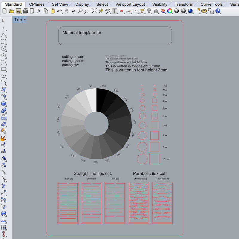
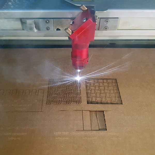
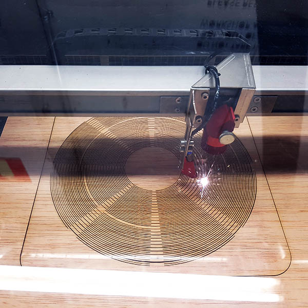
First we did some simple power/speed tests in order to find some right settings for cutting 4mm cardboard and 3mm plywood. The test consisted on multiple circles, each of them in a different color, in order to set a different power/speed to each of them. We always kept the Frequency at 1000Hz. The optimal results for us were:
Cardboard 4mm:
Cutting: 30% power - 0.9 speed
Engraving(vector): 5% power - 1.5 speed
Plywood 3mm:
Cutting: 80% power - 1.5 speed
Engraving(vector): 30% power - 3 speed

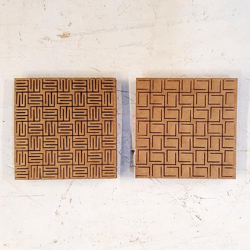
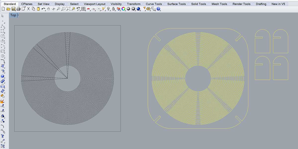
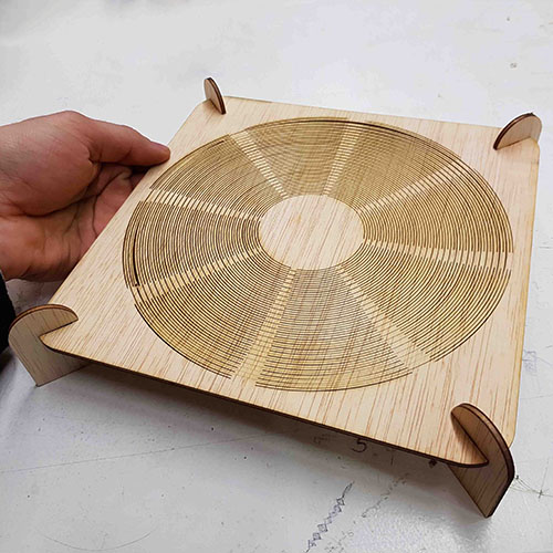
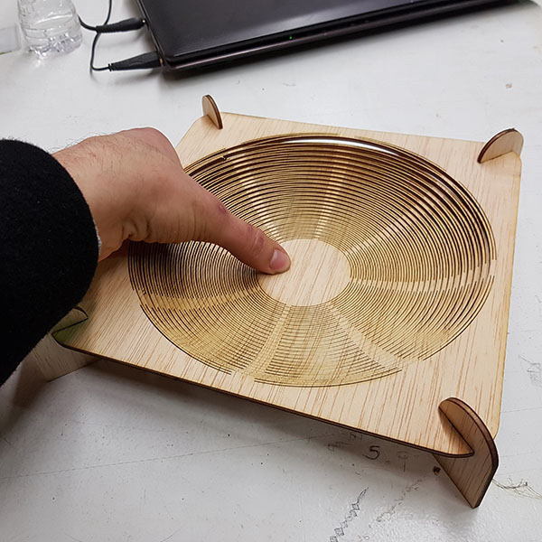
Once we had these values, we used them on an already made template an adapted it to our needs with Rhino. It has different cutting sizes (straight and curve lines), different rastering shades, different text sizes and a few living hinge samples.
The template is printed from Rhino to JobControl. The wheel is made of solid hatches with different shades of grey, which will then be read JobControl as an image. Red lines are vector cutting. Black text is read in JobControl as an image to raster. However, we ended up exploding the text in Rhino in order to have it as a vector, but the text ended up with no fill, just the boundary of the letters (Maybe there's a better way to have a solid filled vector text?)
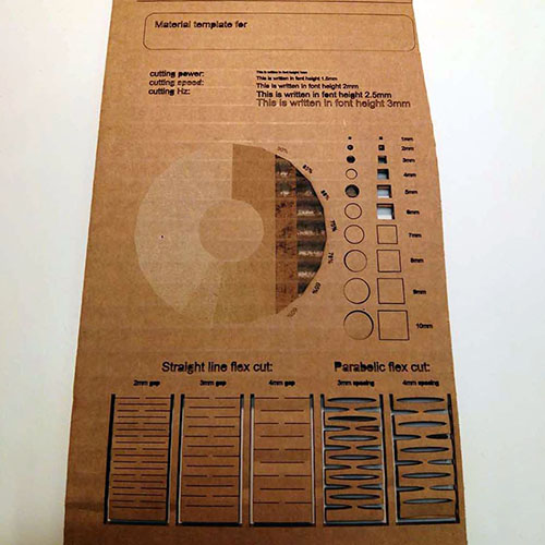
Cardboard 4mm:
We ended up modifying the power of the rastering, since it was burning the first layer of cardboard. We set the speed to 90 but we need to test more on the power and the rastering engraving texture, since the result could be better.
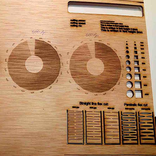
Plywood 3mm:
The same procedure was followed for the plywood. We did a few tests for the rastering engraving, but the result did not fully convince us. Looks like rising the DPI resolution improves the contrasts of the shades. We'll have to keep testing on that.
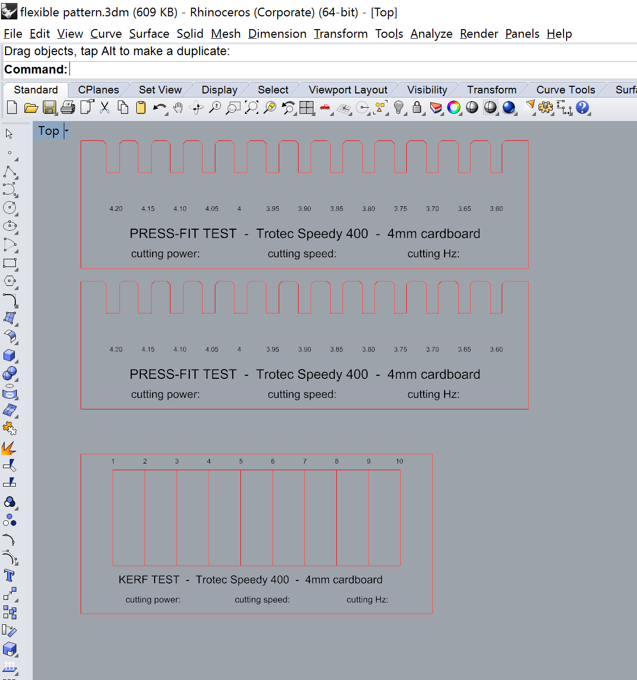
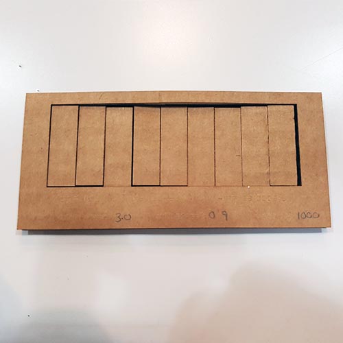
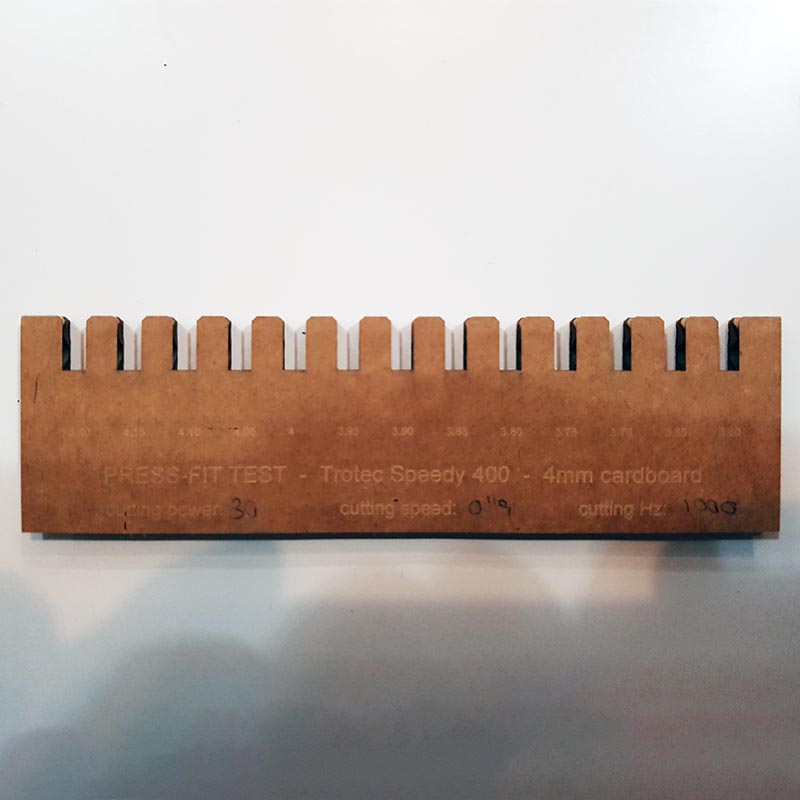
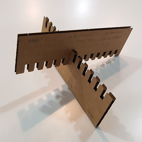
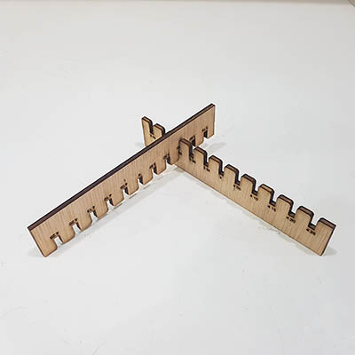
We did a test in order to find the right interlocking nodes and the kerf for both cardboard and plywood. Following other templates, we created our own templates and cut them with the laser. For the press-fit test, we ended up with the following results
Cardboard 4mm:
Fitting gap 3.85mm is quite strong and easy to fit. 3.80 can also be forced to interlock but it's a bit harder. One classmate told us that 3.85 is good for a low quantity of gaps, but if the piece has several ones, it will become harder and hard to interlock the pieces, since each interlocking is pushing the material away from it, squeezing the adjacent gaps.
Plywood 3mm:
A big mistake was done here. We used the same template from the 4mm cardboard to the 3mm wood. The gaps were obviously too big for the wood to interlock correctly. Measure twice, cut once. We ended up finding 2.90-2.95 is a good value for the gap. However not every 3mm plywood is actually 3mm thick,it changes slightly. So I guess a little test should be done for every plywood sheet.
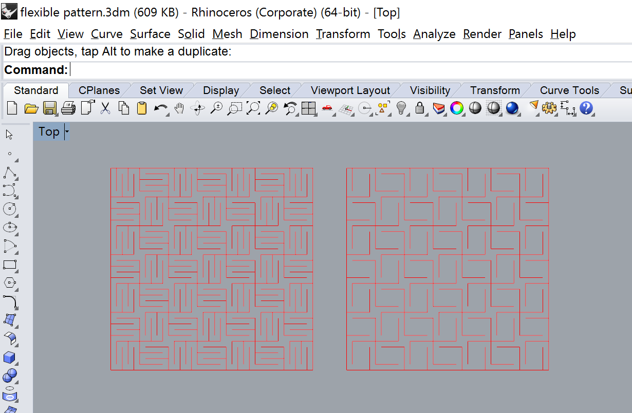
I am in love with living hinges. Turning something rigid into flexible is kind of magic. I had already experienced with living hinges before. However I wanted to keep exploring this way. I designed two flexible patterns in cardboard and plywood. In cardboard, it's easy to make anything flexible, but at the same time it's very weak. I think wood is more interesting for this technique. However my patterns were not as flexible as I thought. One of them broke when trying to bend them. The other one is not so flexible in the X or Y direction, but it is diagonally.
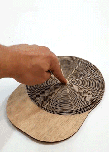
Then I wanted to try a round living hinge. The first try was not so flexible. Too small and not long enough cuts.
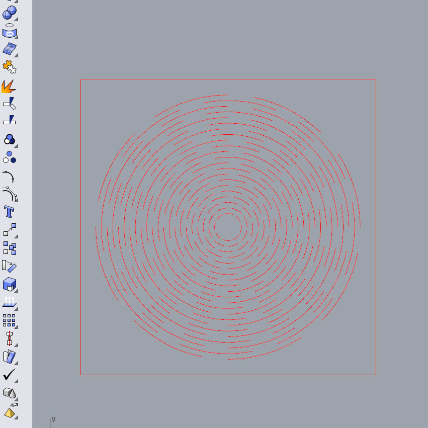
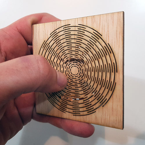
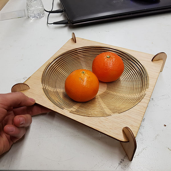
Then I made a bigger version of it. It resulted very flexible, however also a bit weak. Anyway I was happy enough with it for now. Then I cut a few legs with a press-fit join and turned my flexible round test into a fruit bowl!
Then I decided to go further and design a hat.

TA-DA!
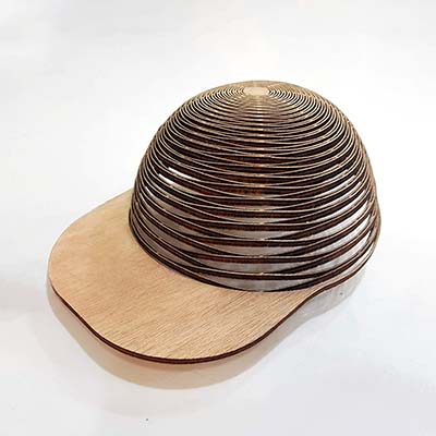
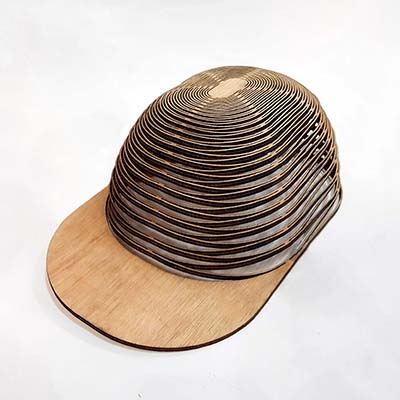
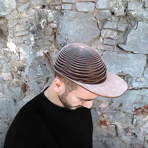
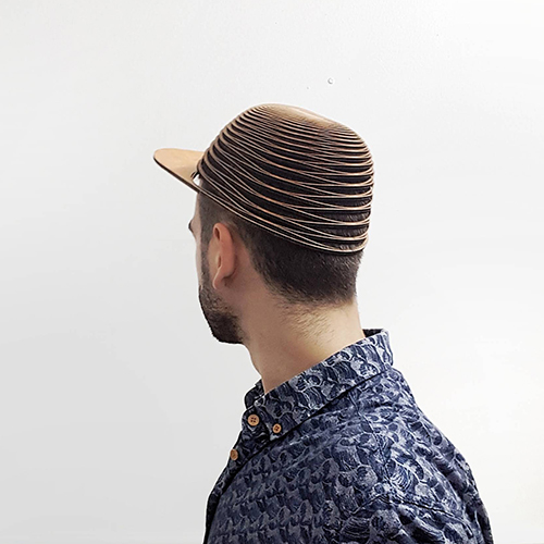
It's a bit fragile because of the plywood, but a better wood would most likely solve this problem.
Making my construction kit
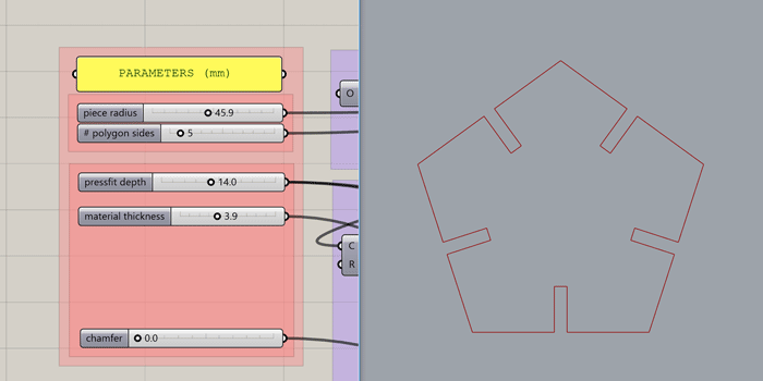
I decided to design my construction kit with Grasshopper, which is a plugin to turn Rhino into parametric. The good thing about parametrizing a design is that you can make changes easy and fast without having to redesign things from scratch. It also helps you think about your design and the key parameters that make it possible. This is my grasshopper design for the press-fit kit:
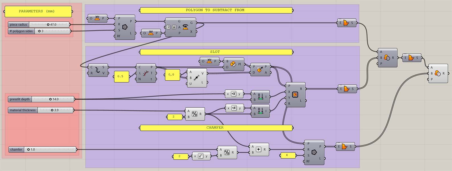
Briefly the process I followed is:
-We have a polygon, which we explode in order to get the segments.
-On each of those segments we find the middle point.
-On those points we set a plane and we orient it according to the center of the polygon.
-On each of these new planes we create a rectangle (these will be the fitting slots).
-We subtract these rectangles to the original polygon.
-On each of the planes we create a square (these will be the chamfers).
-We subtract these squares to the resulted geometry.
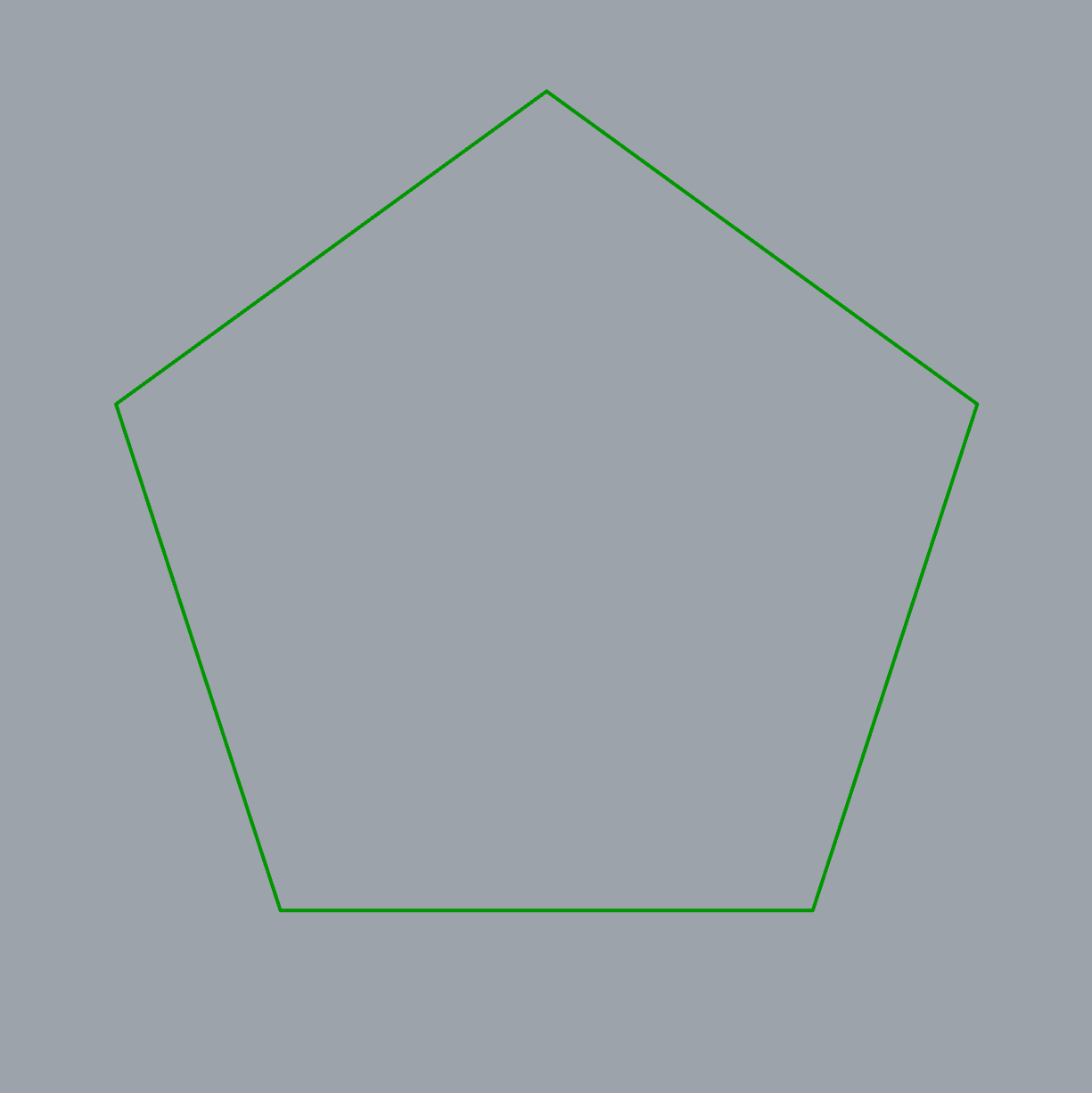
Because the design is now parametric, you can change it according to a few parameters, such as the number of polygon sides:
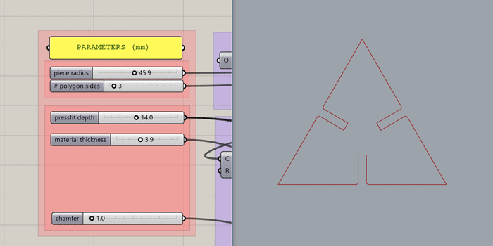
The overall size:
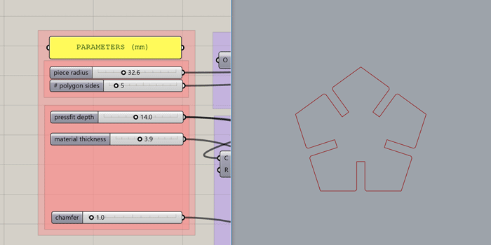
The depth of the fitting slot:
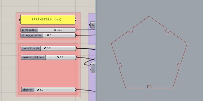
The width of the slot (or the thickness of the material):
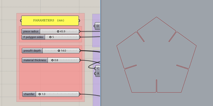
The length of the chamfer to make the fitting easier:
Before cutting the press-fit kit, I'll cut a small test to check the right slot width for a 2.5mm plywood.
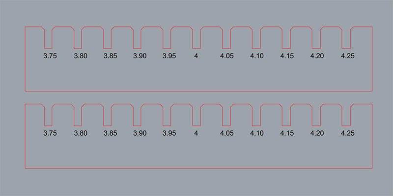
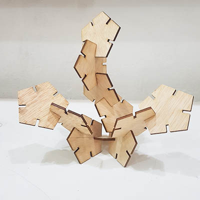
For a 4mm plywood, a gap of 3.85mm or 3.90mm fits okay. And here is the final kit!
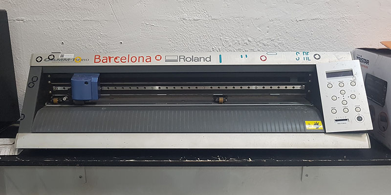
Vinyl cutter
The vinyl cutter is great for cutting stickers, heat-pressing designs for textiles, reflective materials not suitable for the laser or materials that release toxic vapors when lasered. We'll use the Roland GS-24 vinyl cutter.
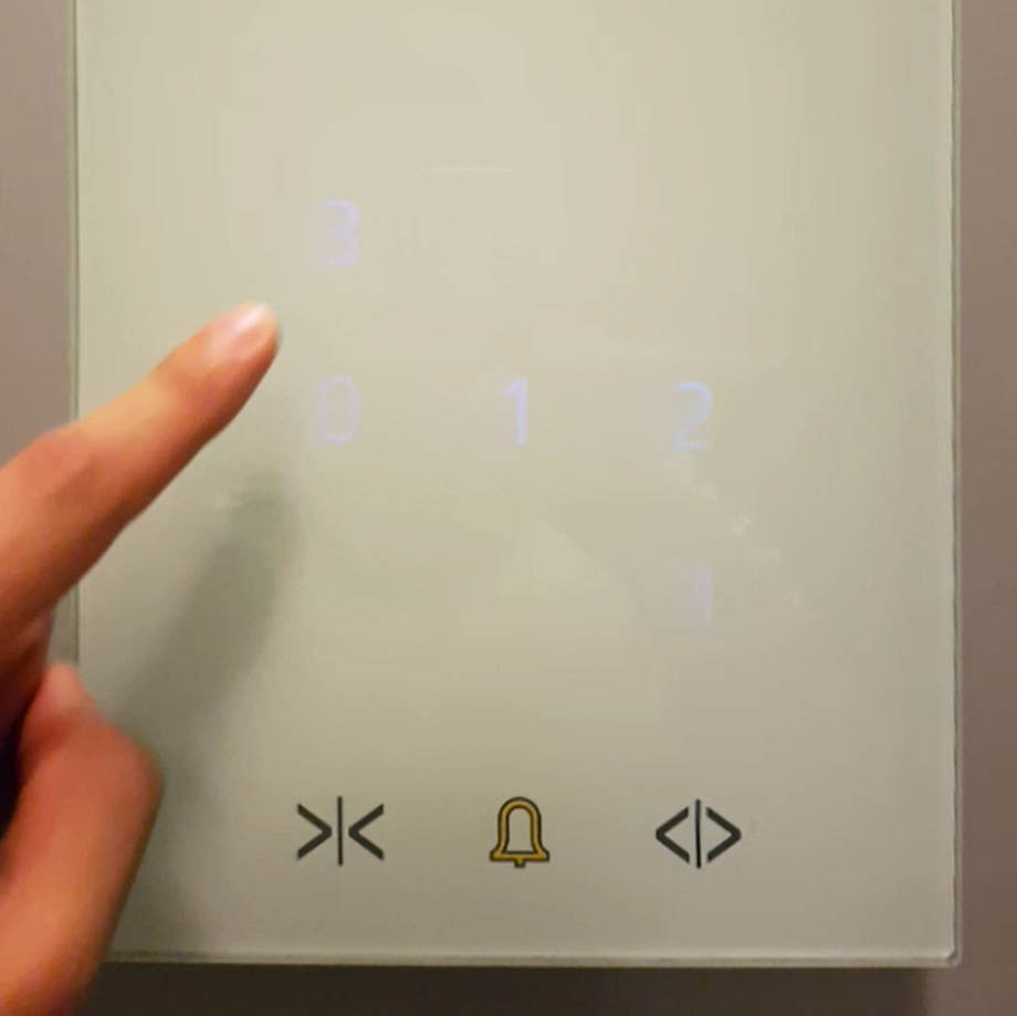
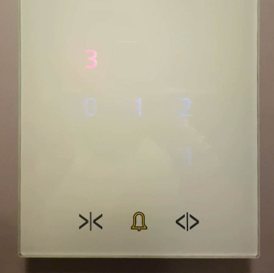
The building where I live has an elevator with a touch panel in which the numbers are barely visible. It's hard to find where to press and only when you have pressed the number you can see something. For this reason, I will cut some numbers and stick them on the panel so it's easier to see what floor number you are pressing.
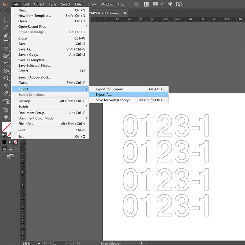
First I did the numbers in Illustrator. For that I just used the Text Tool and turned it into outlines by Type > Create Outlines. I made sure the size of the design was at the same scale as the numbers in my elevator panel. Then exported the design into .svg.
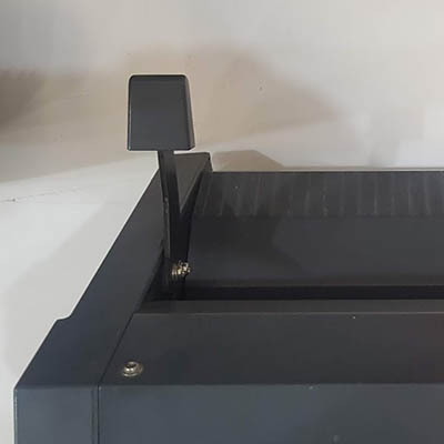
Then set up the vinyl cutter. Place your material in the machine. The lever on the back will lift up the rolls allowing you to insert the vinyl. The rolls always have to be inside the white areas. The vinyl has to bee under the two rolls.
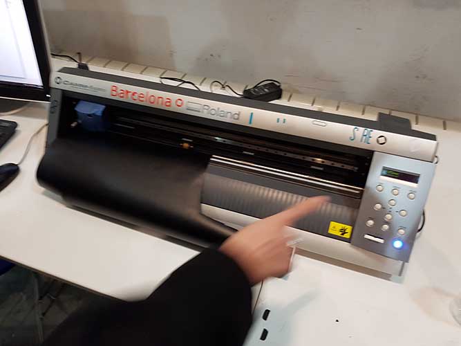
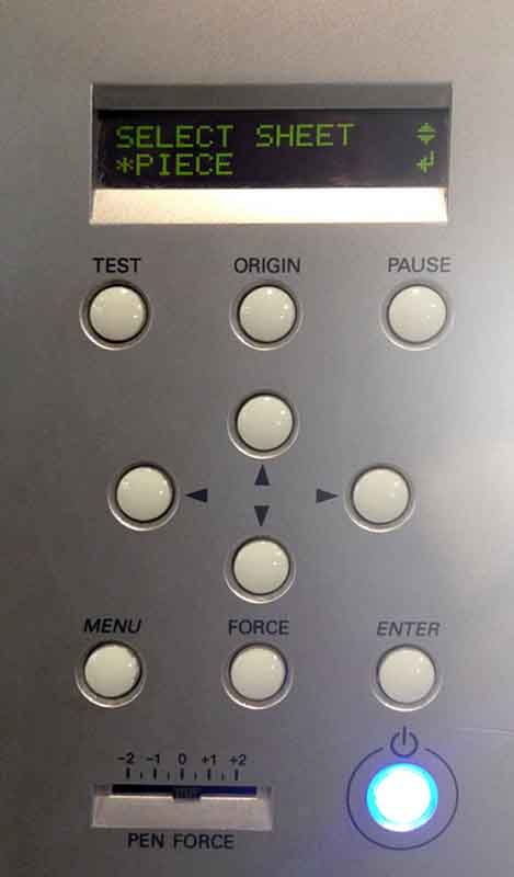
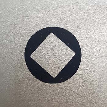
Turn on the machine and measure the vinyl sheet by Select sheet > Roll/Piece/Edge. This will tell the machine what width of material to expect and mesure it. In this case I selected Piece so it can measure the length and width of the vinyl piece. On the machine panel, you can click on test to check how good the cut is. It will cut a circle with a square inside. If the test doesn't turn out well, you can adjust the blade by turning the blade holder. Also you can adust the Pen Force on the machine panel.

Then I used Roland CutStudio, the software that operates the vinyl cutter. Once there, import the .svg file. Then go to File > Cutting Properties > Properties. In Cutting Area click on Get from machine and you'll get the proper size of your vinyl piece. Then go to File > Cutting and check the result!
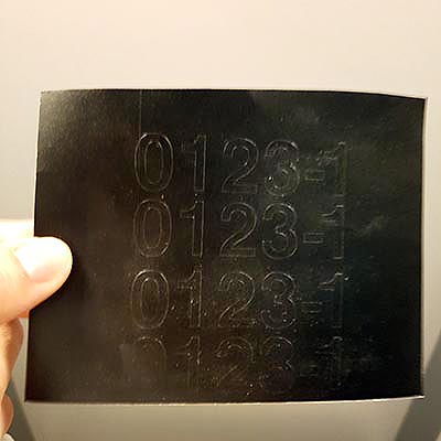
Time to stick them on the panel. Much better now! My neighbours will love it!


download files

This work is licensed under a Creative Commons Attribution-NonCommercial-ShareAlike 4.0 International License.