week 4 - electronics production
-group assignment: characterize the specifications of your PCB production process
-individual assignment: make an in-circuit programmer by milling the PCB, make an in-circuit programmer by milling the PCB
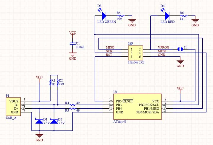
For this week assignment we had to make a AVR ISP programmer/board by using a milled PCB, soldering the components and programming the board. I followed this example.
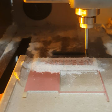
For millig the PCB board we'll use the Roland monoFab SRM-20 small milling machine. It can precission mill a wide range of materials (modeling wax, chemical wood, foam, acrylic, poly acetate, ABS and PC board...)
First I downloaded the PNG files for the traces and the outline
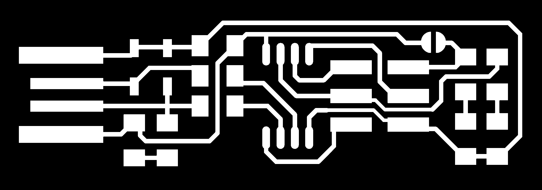

Then you can use Mods or FabModules to generate the toolpath for the milling machine. In my case I used FabModules. You need to do these steps twice, one for the traces PNG and one for the outline PNG. These are the steps for the traces:

The setting of "Number of offsets" is set to 4 by default, you can increase or reduce the amount of cooper to be milled. If you set it to "-1" it will mill all the copper that is not part of the traces. Once you click on "Calculate" you will see a preview of the toolpath. Check everything looks fine (sometimes copper traces can be undesiredly connected, if that happens you can try FabModules or make the path separation bigger in the traces PNG...) and then click on "Save" to generate the .rml file for the milling machine software.
For the outline PNG, the steps are the same except we will choose "PCB outline (1/32)" in the "process" menu.
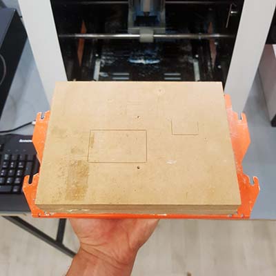
For milling the PCB board we will use FR-1 (PCB blanks). FR-1 is a hard, flat material that consists of a thin layer of copper over a non-conductive phenolic resin.
Take the plate out of the milling machine. In our fab lab, the plate has a wooden block stuck on it. Make sure the surface is flat and clean, any little piece of dirt can make it be not 100% flat and ruin the work. On the wood surface you will stick the PCB. For that, I took a blank PCB that was already milled, but my design still fits in it, so it's ok. Carefully put some doble-side tape on the rear side of the PCB and stick it on the wood surface, making sure it's straight placed.

Now open the VPanel in order to move the machine to a comfortable position to change the bit (1/64 for traces and 1/32 for outline). Tighten the bit well so it doesn't wiggle when milling. Now you need to set the zero. First move the machine in increments of x100, x10 and x1 and set the origin for X/Y. For that you can lower the bit to get closer to the PCB, without touching it.
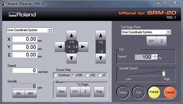
To set the origin for Z, lower the tool near to the PCB without toching it and then loosen the bit to let it fall (carefully!) on the board. Then tighten it well and now you can set the origin for Z.
Now press Cut, Load File and then Output. The spindle will start. You can lower the Cut Speed (not the Spindle Speed!) to see if it does the work right and gradually increase it to 100%.
You can Pause and Resume your work and click on View (the machine will bring the plate closer to you) to check how the work is being done.
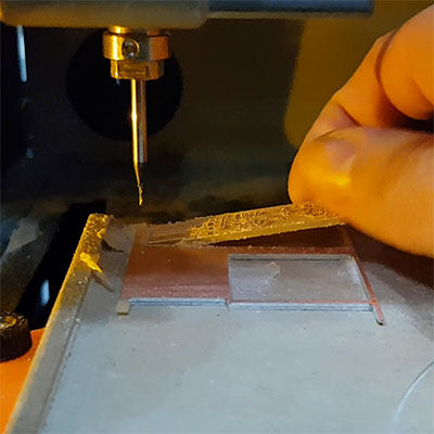
When the milling work is ended, we can take out the piece. Don't forget to clean the machine so others can use it.
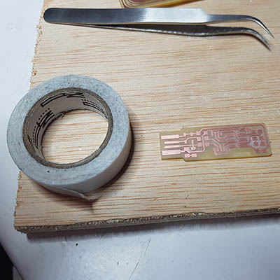
Ok, PCB milling done! It is also good to clean the resulted PCB board using a steel-wool to get rid of little cooper parts.
Before soldering the components, it is better to tape the PCB on something bigger such a piece of wood, in order to give it some weight so we won't move it with the soldering iron. You can also hold the PCB with a vice.
For soldering the parts to the PCB, I used the schematic and board image below as a reference for component values and placement. It is better to start with the most difficult parts (the ATtiny) first, so you have the most access. Install the ISP header last, as it is large and can get in your way if you do it earlier.
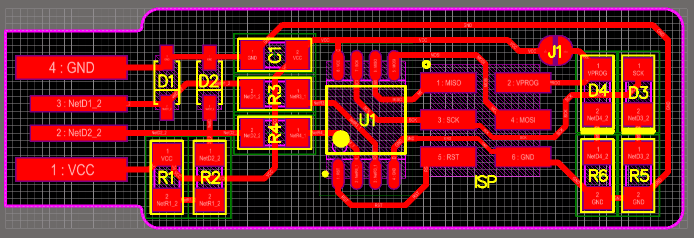
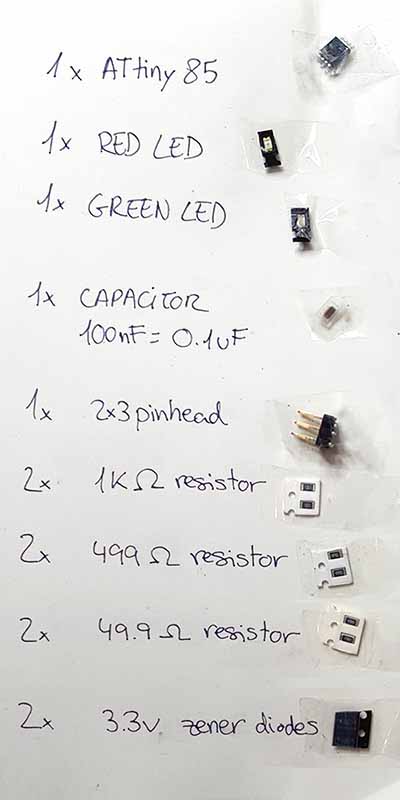
These are all the components I used:
1x ATtiny85 (ATtiny45 can also be used)
2x 1kΩ resistors
2x 499Ω resistors
2x 49Ω resistors
2x 3.3v zener diodes
1x red LED
1x green LED
1x 100nF capacitor
1x 2x3 pin header
Note the components that must be installed in the correct orientation:
- The zener diodes are marked with a line on the cathode side.
- The LED cathodes on the PCB drawing are marked with dots and thicker lines. There is usually a green or black line visible on the cathode side.
- The ATtiny45 marks pin 1 with a dot laser-etched into the corner of the package. Pin 1 is marked in the drawing with a dot as well.
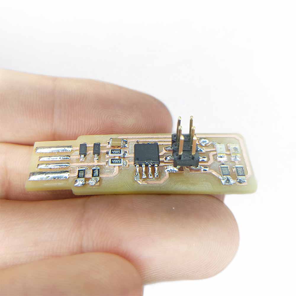
Job done! Soldering tiny components is tricky and you can easily miss some tiny connections. Check each soldering with a magnifying glass, since some connections can look like they are fully soldered when in fact they are not. Remember to create a little solder bridge on the jumper near the ISP header. In this way the header can be used to program the ATtiny. Once it will be programmed, this bridge should be removed to turn the board into your future programmer.
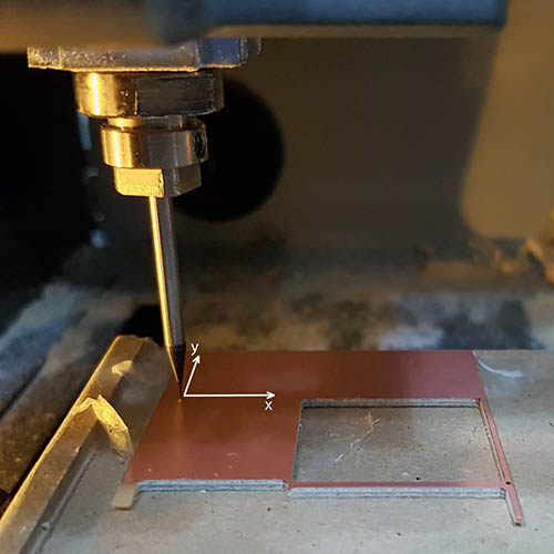
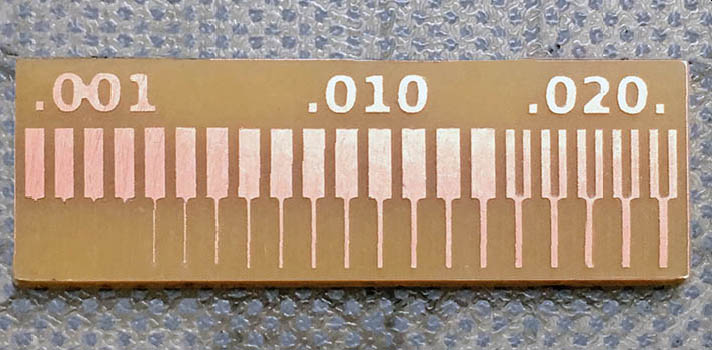
But this PCB traces design was taken from Brian's example. PCBs traces on my future boards will have to be designed and defined by me. So, by following the same steps as before, I also milled a PCB as a test to find the finest traces I will be able to mill.
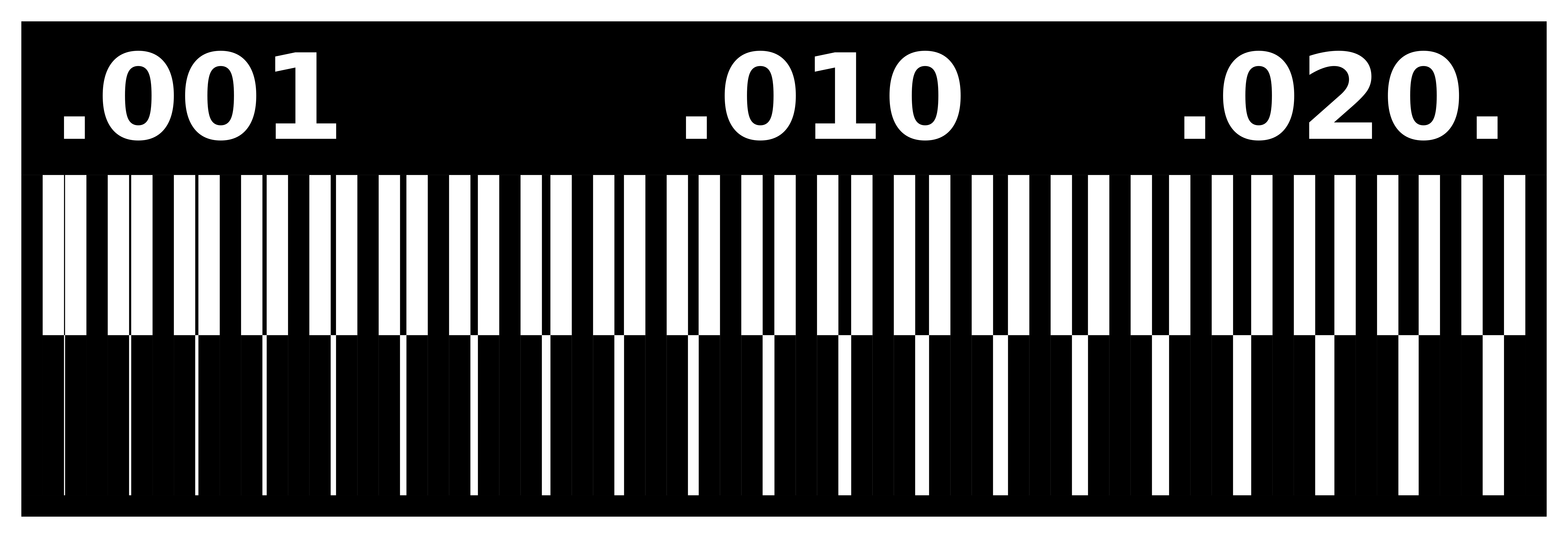

Once milled, I cleaned it with a razor and sanded it with a metal sponge to get a clean result. Seems like widths around .001mm are too risky to mill, but the near to .01mm look fine.
programming
Time to program the FabTinyISP. But first, you need to install some stuff in your computer, in my case I followed Brian's instructions for Windows step by step.
You need to install these:
-Atmel AVR Toolchain for Windows Installed in C:\Program Files
-GNU make
-Avrdude Installed in C:\Program Files
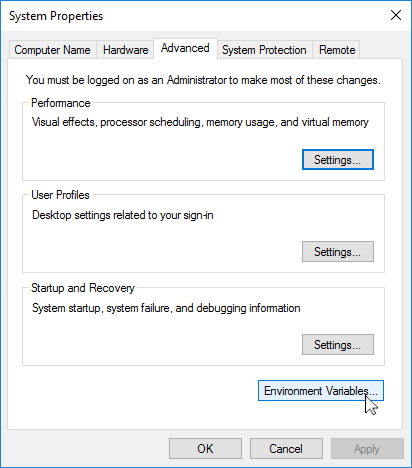
Now we need to tell Windows where to locate all of the tools we've just installed when we type their names on the command line.
Go to Start > Control Panel > System > Advanced System Settings > Environment Variables
and add the following three values, as separate items:
- C:\Program Files\avr8-gnu-toolchain\bin
- C:\Program Files (x86)\GnuWin32\bin
- C:\Program Files\avrdude

Then download and launch Zadig. The USBtiny programmers use a generic libusb driver, but Windows 10's driver signing policy makes the installation more complicated. Fortunately, the tool Zadig helps with this. Plug in your programmer, and select the "USBtinySPI" device in the list. (If it doesn't show up, go to the Options menu and click "List All Devices". The driver you want to install (to the right of the green arrow) is either libusb-win32 or libusb0. Click the "Install Driver" button. You should only have to do this once.

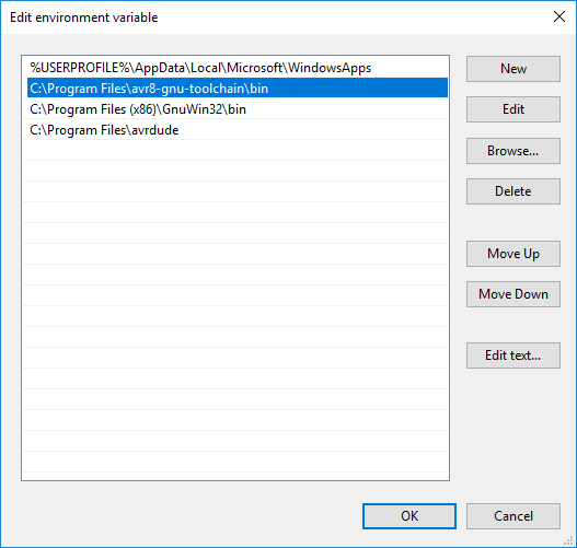
Now check that the commands we installed work ok. For that, open GitBash and type these 3 commands.
The avrdude message we get in response (initialization failed...) means that avrdude successfully found the programmer, but failed to talk to a target board (expected because we don't have anything connected to the programmer right now.
Then download the firmware source code and extract the zip file. Open the terminal program (GitBash) and cd into the source code directory. Run make. This will build the hex file that will get programmed onto the ATtiny. When the command completes, you now have a file called fts_firmware.hex.
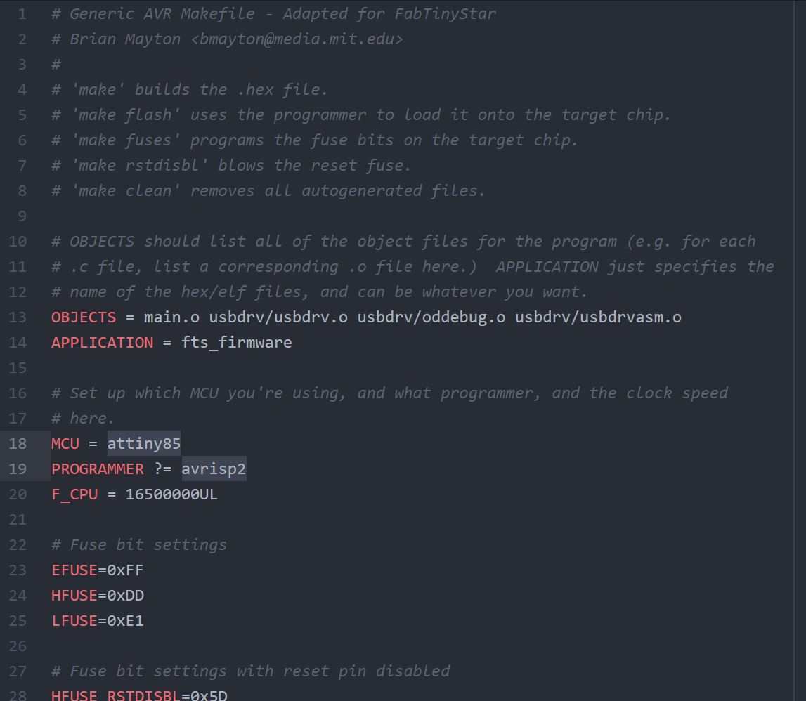
Now we need to edit the Makefile for the type of programmer we are using to program our board. It is important to use a text editor intended for programmers (programs like Notepad or WordPad can add formatting information that breaks the file). In my case I used Atom. When editing the Makefile, near the top of the file, find the line that says PROGRAMMER ?= usbtiny and change usbtiny to whatever programmer you're using, in my case avrisp2. I also changed the name of the MCU from attiny45 to attiny85 since the the one I am using is the 85.
Everything is now ready for flashing the ATtiny. Take the ATAVRISP2 programmer and connect it to our FabTinyISP through it's ISP header. Watch out you connect it with the right orientation (black cable is the ground).

In GitBash run the command: make flash to erase the target chip, and program its flash memory with the contents of the .hex file. Then run make fuses to set up all of the fuses, except the one that disables the reset pin.
Before turning my board into a programmer, I tested the USB functionality. To do that, I unplugged everything and I plugged to USB port my board alone. I verified that it appeared in the Device Manager of Windows, and it was visible. Then I re-connected the programmer to my board and then to the USB ports again and runned the command "rstdisbl". This does the same thing as the make fuses command, but this time it's going to include that reset disable bit as well. Now you can remove the bridge on the solder jumper, thus breaking the connection.
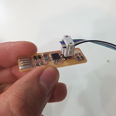
Now I have my own ISP programmer!.
download files

This work is licensed under a Creative Commons Attribution-NonCommercial-ShareAlike 4.0 International License.