Week 13 - Output devices
Assignment
Add an output device to a microcontroller board you've designed and program it to do something.
The idea
for this assignment I'll do a classic, a board connected to a LCD screen. I am taking as a guide the assignment made by Xavi Dominguez , taking advantage of the experiences that he had during the accomplishment of this exercise.
The board
I took Xavi's and Neil's board as a reference, I designed my board with Eagle. This is the list of elements I used, You will find all at the Fab Inventory):
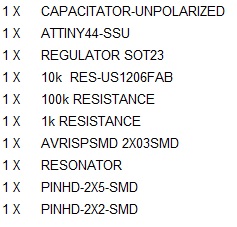
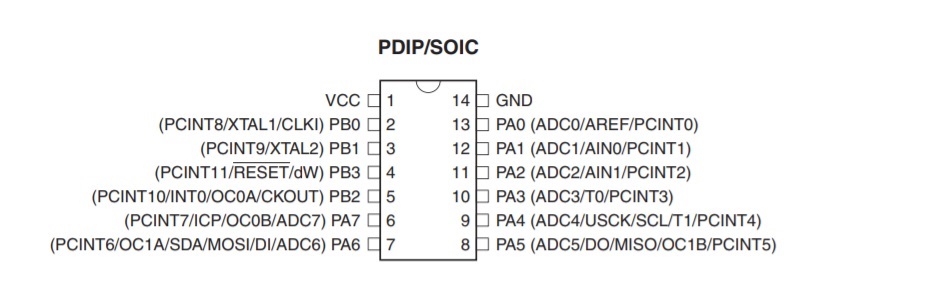
For this board we use the Attiny44, it's important to read "again" the data sheet.
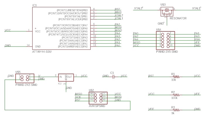
This is the result of the chematic design. To know more about how to design in Eagle take a look al the Electronics Design assignment
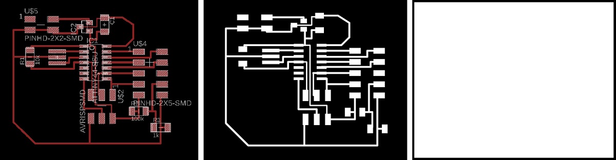
And the result of the draw in the window design generator
This is the result of the chematic design,
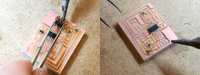
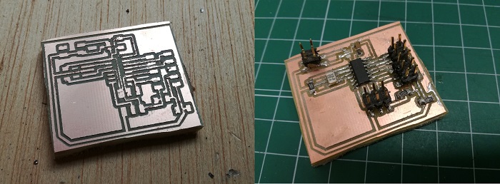
you can notice that the board that I am welding is not the same as the final result, that is because I have manufactured it twice because of an accident with the first board
This is the result of the milling and soldering process. To know more about this process take a look al the Electronics Production assignment
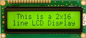
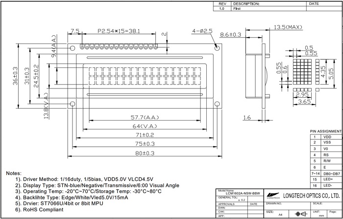
The 16x02 LCD screen
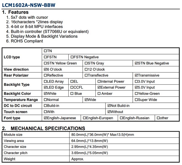
I will use one of the most common LCD screens in the market, You can chack the Data sheet here
I think the best way to understand it is to contrast the data sheet and documented examples
Programming
I'm using Xavi's code for this assignment, I just change a little bit the text to show on the lcd screen.
In any case the important thing is to understand the code.
For a better understanding on the use of input/outputs, registers in AVR microcontrollers there is a nice tutorial
First of all, we must include some useful headers to our c code, which are avr/io.h, util/delay.h and avr/pgmspace.h.
avr/io.h: This header is used to include the apropiate Input/Output definitions and their respective bits value for the microcontroller we are using.
util/delay.h: Includes some busy-wait functions that allow us to create delays specifying actual time values rahter than a number of cycles to wait for.
avr/pgmspace.h: Provides interfaces for a program to access stored data in program space (flash memory) of the device.
//

				//
// hello.LCD.44.c
//
// LCD hello-world
//
// set lfuse to 0x5E for 20 MHz xtal
//
// Neil Gershenfeld modified by Javier Hernandez
// 11/14/10
//
// (c) Massachusetts Institute of Technology 2010
// This work may be reproduced, modified, distributed,
// performed, and displayed for any purpose. Copyright is
// retained and must be preserved. The work is provided
// as is; no warranty is provided, and users accept all
// liability.
//

#include  avr/io.h>
#include util/delay.h>
#include avr/pgmspace.h>

#define output(directions,pin) (directions |= pin) // set port direction for output
#define set(port,pin) (port |= pin) // set port pin
#define clear(port,pin) (port &= (~pin)) // clear port pin
#define pin_test(pins,pin) (pins & pin) // test for port pin
#define bit_test(byte,bit) (byte & (1 << bit)) // test for bit set

#define LCD_port PORTA
#define LCD_direction DDRA
#define DB7 (1 << PA0)
#define DB6 (1 << PA1)
#define DB5 (1 << PA2)
#define DB4 (1 << PA3)
#define E (1 << PA4)
#define RS (1 << PA5)

#define long_delay() _delay_ms(1000) // delay before redraw
#define lcd_delay() _delay_ms(10) // delay between commands
#define strobe_delay() _delay_us(1) // delay for strobe

//
// lcd_putchar
//    put character in lcdbyte
//
void lcd_putchar(char lcdbyte) {
   //
   // set RS for data
   //
   set(LCD_port, RS);
   //
   // output high nibble
   //
   if bit_test(lcdbyte, 7)
      set(LCD_port, DB7);
   else
      clear(LCD_port, DB7);
   if bit_test(lcdbyte, 6)
      set(LCD_port, DB6);
   else
      clear(LCD_port, DB6);
   if bit_test(lcdbyte, 5)
      set(LCD_port, DB5);
   else
      clear(LCD_port, DB5);
   if bit_test(lcdbyte, 4)
      set(LCD_port, DB4);
   else
      clear(LCD_port, DB4);
   //
   // strobe E
   //
   strobe_delay();
   set(LCD_port, E);
   strobe_delay();
   clear(LCD_port, E);
   //
   // wait
   //
   lcd_delay();
   //
   // output low nibble
   //
   if bit_test(lcdbyte, 3)
      set(LCD_port, DB7);
   else
      clear(LCD_port, DB7);
   if bit_test(lcdbyte, 2)
      set(LCD_port, DB6);
   else
      clear(LCD_port, DB6);
   if bit_test(lcdbyte, 1)
      set(LCD_port, DB5);
   else
      clear(LCD_port, DB5);
   if bit_test(lcdbyte, 0)
      set(LCD_port, DB4);
   else
      clear(LCD_port, DB4);
   //
   // strobe E
   //
   strobe_delay();
   set(LCD_port, E);
   strobe_delay();
   clear(LCD_port, E);
   //
   // wait and return
   //
   lcd_delay();
   }
//
// lcd_putcmd
//    put command in lcdbyte
//
void lcd_putcmd(char lcdbyte) {
   //
   // clear RS for command
   //
   clear(LCD_port, RS);
   //
   // output command bits
   //
   PORTA = lcdbyte;
   //
   // strobe E
   //
   strobe_delay();
   set(LCD_port, E);
   strobe_delay();
   clear(LCD_port, E);
   //
   // wait and return
   //
   lcd_delay();
   }
//
// lcd_putstring
//    put a null-terminated string in flash
//
void lcd_putstring(PGM_P message) {
   static uint8_t index;
   static char chr;
   index = 0;
   while (1) {
      chr = pgm_read_byte(&(message[index]));
      if (chr == 0)
         return;
      lcd_putchar(chr);
      ++index;
      }
   }
//
// lcd_init
//    initialize the LCD
//
void lcd_init() {
   //
   // power-up delay
   //
   lcd_delay();
   //
   // initialization sequence
   //
   lcd_putcmd(DB5+DB4);
   lcd_putcmd(DB5+DB4);
   lcd_putcmd(DB5+DB4);
   //
   // 4-bit interface
   //
   lcd_putcmd(DB5);
   //
   // two lines, 5x7 font
   //
   lcd_putcmd(DB5);
   lcd_putcmd(DB7);
   //
   // display on
   //
   lcd_putcmd(0);
   lcd_putcmd(DB7+DB6+DB5);
   //
   // entry mode
   //
   lcd_putcmd(0);
   lcd_putcmd(DB6+DB5);
   }

int main(void) {
   //
   // main
   //
   // set clock divider to /1
   //
   CLKPR = (1 << CLKPCE);
   CLKPR = (0 << CLKPS3) | (0 << CLKPS2) | (0 << CLKPS1) | (0 << CLKPS0);
   //
   // initialize LCD pins
   //
   clear(LCD_port, DB7);
   output(LCD_direction, DB7);
   clear(LCD_port, DB6);
   output(LCD_direction, DB6);
   clear(LCD_port, DB5);
   output(LCD_direction, DB5);
   clear(LCD_port, DB4);
   output(LCD_direction, DB4);
   clear(LCD_port, E);
   output(LCD_direction, E);
   clear(LCD_port, RS);
   output(LCD_direction, RS);
   //
   // initialize LCD
   //
   lcd_init();
   //
   // main loop
   //
   while (1) {
      //
      // go to zero position
      //
      lcd_putcmd(0);
      lcd_putcmd(DB5);
      //
      // print first line from flash
      //
      static const char line1[] PROGMEM = "Turning on..";
      lcd_putstring((PGM_P) line1);
      //
      // move to second line
      //
      lcd_putcmd(DB7+DB6);
      lcd_putcmd(0);
      //
      // print second line from flash
      //
      static const char line2[] PROGMEM = "Wait!";
      lcd_putstring((PGM_P) line2);
      //
      // pause
      //
      long_delay();
      //
      // clear display
      //
      lcd_putcmd(0);
      lcd_putcmd(DB4);
      }
   }
Now we can make makefile: sudo make -f hello.LCD.44.make
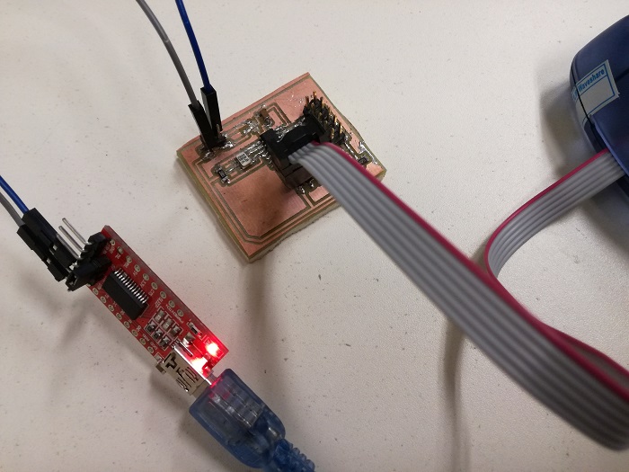
I'm using AVRISPMK2 to program the board, my fabISP is having bad days :-(, and a ftdi232 board to power the board
Wiring
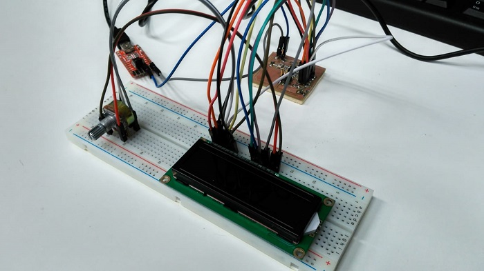
I will use the ftdi232 board to feed the board and the lcd screen. I will need also a potentiometer to regulate the intenisty of the light of the lcd screen. Instead of soldering a female header to LCD board to connect the wires between the boards I will use a protoboard, better option if you are tinkering
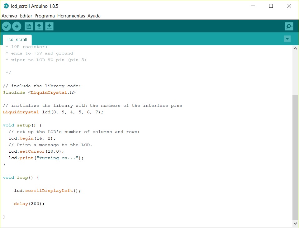
Programming with Arduino
This time I'm going to try programming through the Arduino IDE.
First, we include the LiquidCrystal library, which allows our Arduino board to control LiquidCrystal displays (LCDs) based on the Hitachi HD44780 (or a compatible) chipset.
After that, we must set up the LCD's number of columns and rows, as well as setting text's initial position. In our case, the text that we want to show is: Turning on...
Finally, we enter on an infinite loop where the text will be scrolled to the left infinitely.
This is the Code
//

				/*
  LiquidCrystal Library - scrollDisplayLeft()

 Demonstrates the use a 16x2 LCD display.  The LiquidCrystal
 library works with all LCD displays that are compatible with the
 Hitachi HD44780 driver. There are many of them out there, and you
 can usually tell them by the 16-pin interface.

 This sketch prints "Hello World!" to the LCD and uses the
 scrollDisplayLeft() method to scroll the text.

  The circuit:
 * LCD RS pin to digital pin 12
 * LCD Enable pin to digital pin 11
 * LCD D4 pin to digital pin 5
 * LCD D5 pin to digital pin 4
 * LCD D6 pin to digital pin 3
 * LCD D7 pin to digital pin 2
 * LCD R/W pin to ground
 * 10K resistor:
 * ends to +5V and ground
 * wiper to LCD VO pin (pin 3)

 Library originally added 18 Apr 2008
 by David A. Mellis
 library modified 25 Jul 2009
 by Limor Fried (http://www.ladyada.net)
 example added 9 Jul 2009
 by Tom Igoe
 modified 22 Nov 2010
 by Tom Igoe

 modified by Javier Hernandez

*/

// include the library code:
#include

// initialize the library with the numbers of the interface pins
LiquidCrystal lcd(12, 11, 5, 4, 3, 2);

void setup() {
  // set up the LCD's number of columns and rows:
  lcd.begin(16, 2);
  // set LCD's cursor on a specified location.
  lcd.setCursor(10,0);
  // Print a message to the LCD.
  lcd.print("hello, world!");
}

void loop() {
    // loop where out text will be infinitely scrolled to the left
    lcd.scrollDisplayLeft();
    // wait a bit:
    delay(300);
  }
}
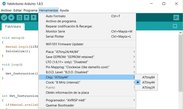
Select the chip - ATtiny44
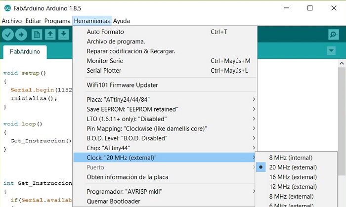
The external clock must be 20MHz
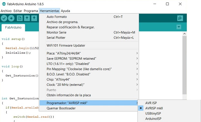
I'n using the AVRISP mkll, so I select it
al finally run bootloader
Run the program