Week 2 - Computer-aided design
Assignment
Model (raster, vector, 2D, 3D, render, animate, simulate, ...) a possible final project, and post it on your class page
Using Gimp and Inkscape

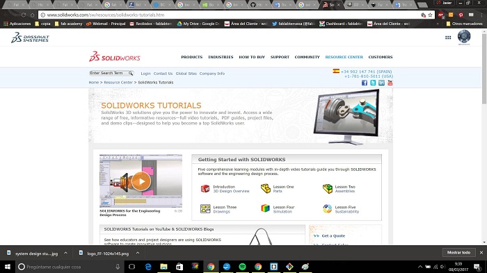
As a regular user of design software it has not been difficult to learn these new softwares. The fact that these sofwares are free is very important since the information can be shared without costs for those interested. In the case of solid works it is different. It is a very complete and versatile software which is used in different design ambits such as universities and design companies. Solid works has a cost but can be obtained.....
Using Gimp and Inkscape

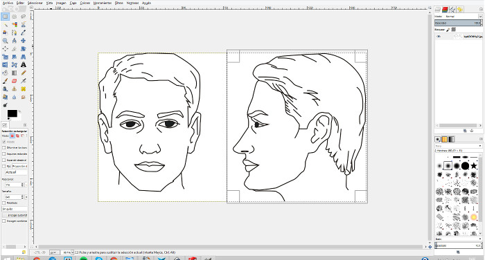
I need to represent the concept of an object. I downloaded an image of Internet to use it. I don't need the whole picture so I cut the image using the rectangle selector "R" and then in the top bar Edit/Cut.
Gimp is a very powerful software and has many tools but in this case I have only used it to cut the image.
Now i change to inkscape.
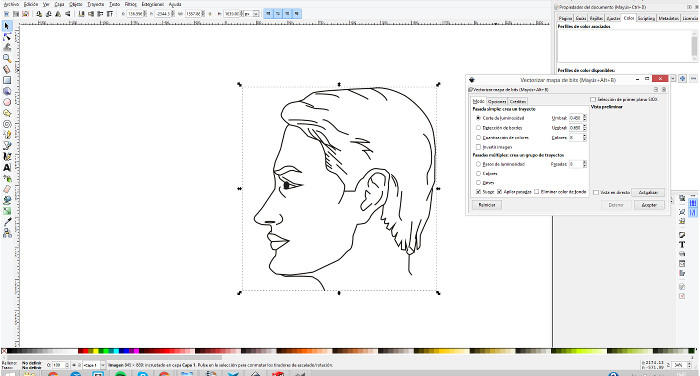
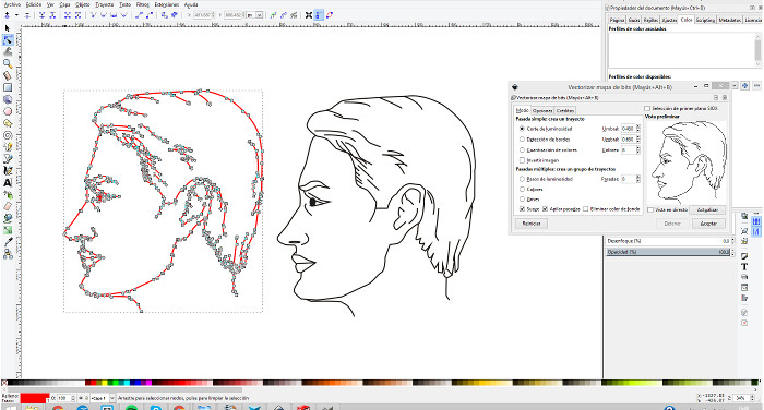
Then I imported the image into inkscape and use the tool to convert it in to a Vector Graphic using the tool on the top bar Path/Trace Bitmap or "Shift+Alt+B
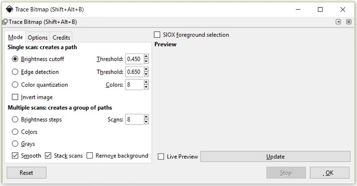
I used the default setup to trace the image, the image i used was easy because it was a b/w image, if you use images whith more details you should play with the different parameters. The image resolution is very important to have good results.
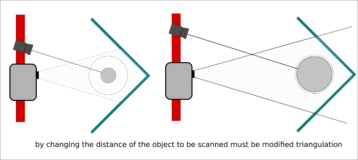
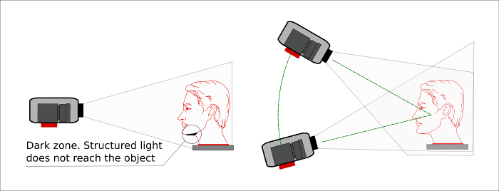
I used Inkscape to make some explanatory diagrams of the functioning of structured light scanner
To draw simple element inkscape is very intuitive and you could get to draw blocks or lines as you have in text editors like word, also modify line thicknesses or fill colors. The good thing begins when you start editing nodes, remember that inkscape is a vector design software.
Using Solid Works
Drawing a Nema stepper motor
To draw the NEMA17 engine, we will work from different parts and an assembly of those parts. In addition to the comments on each step you can see the commands used in the images
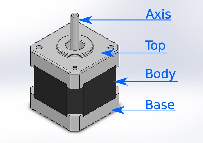
The parts are: Base, Top, Axis and Body
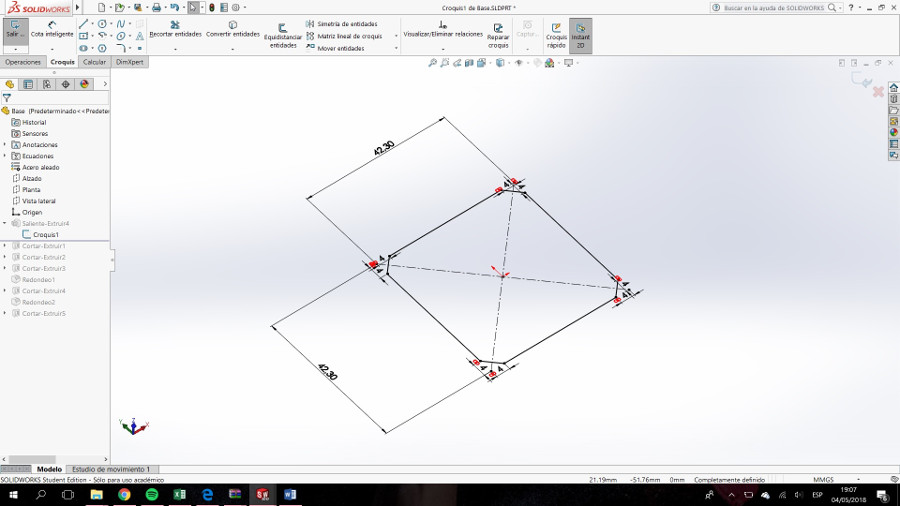
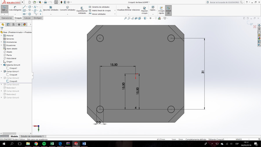
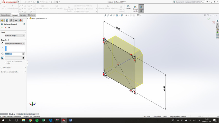
We start with the BASE. We build a square of 42.30 x 42.30 x 12mm. The corners have to be with 4mm chamfer.
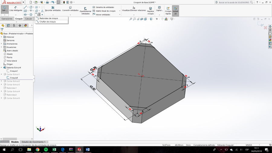
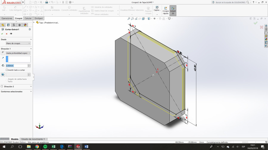
On the upper side we draw the same square only that this time the chamfer must be 7mm.
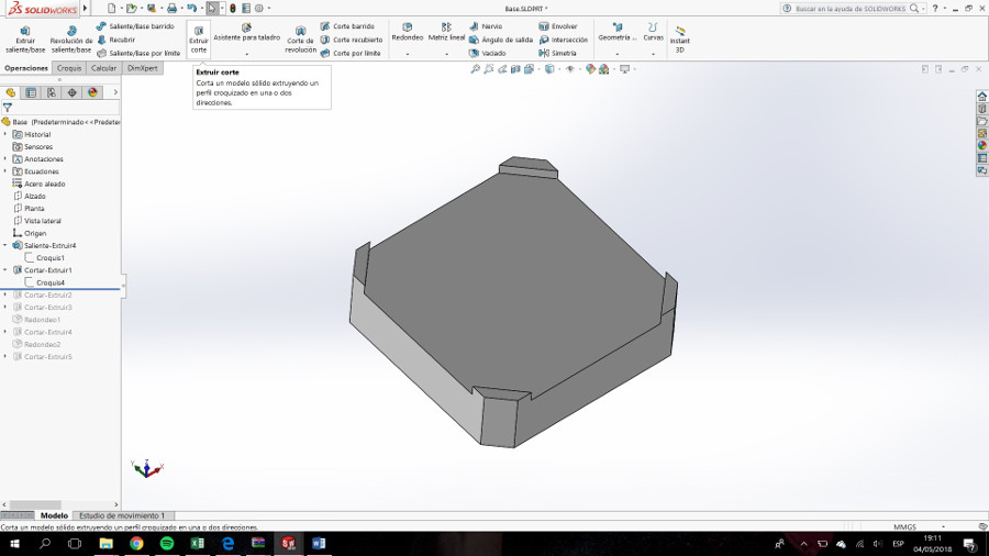
Extrude cut 2mm.
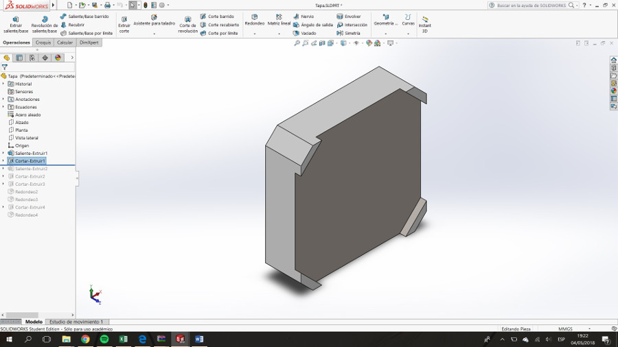
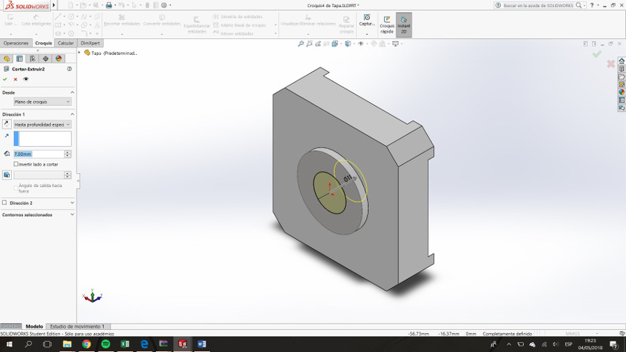
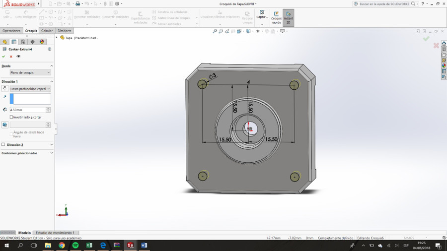
Extrude cut for drills (holes)
Extruded-Cut 5mm for the cavity for the bearing.
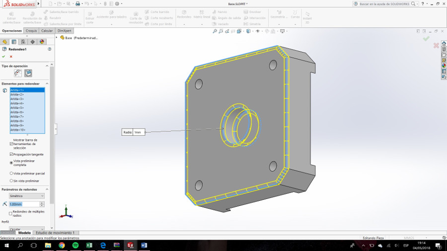
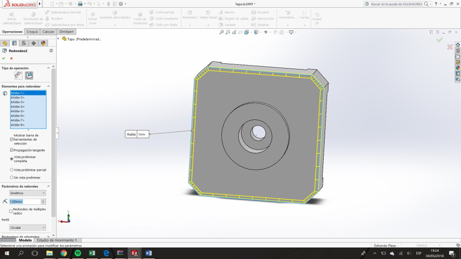
Round the indicated edges
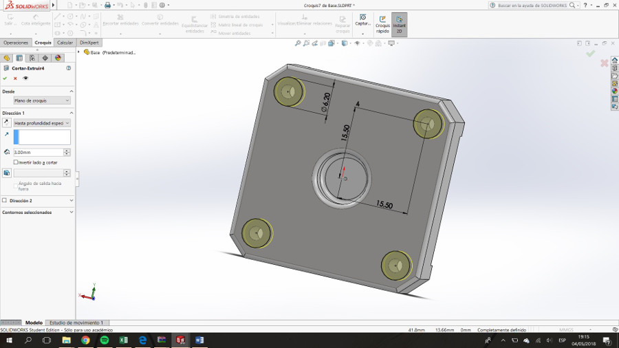
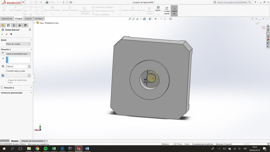
Make the recess for the head of the screws.
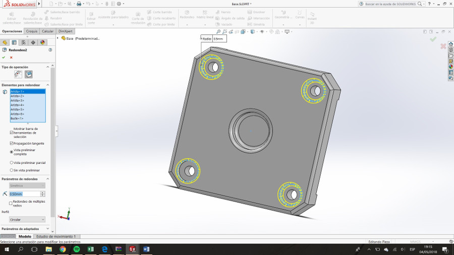
Round off the edges

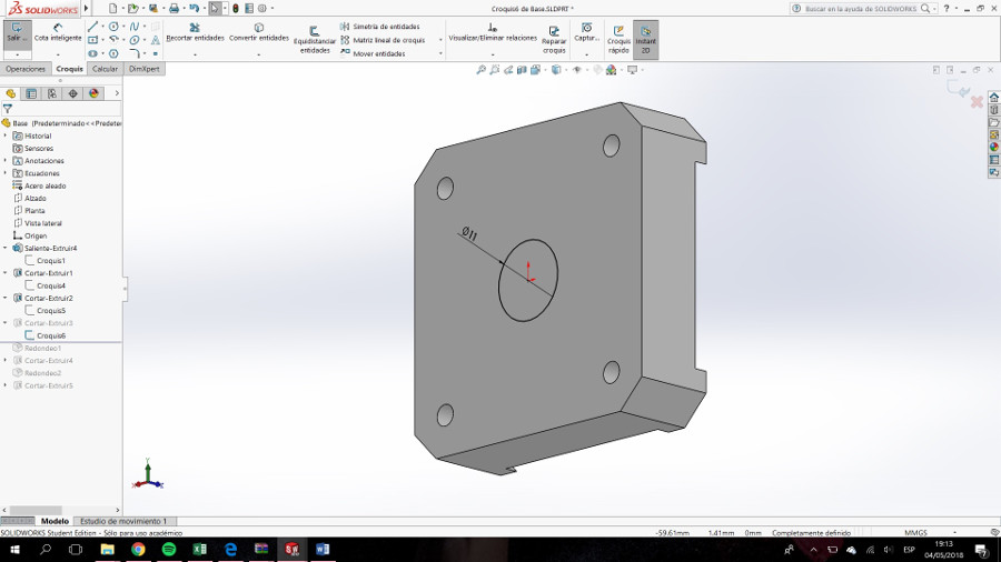
Drill. The axis will pass through here.
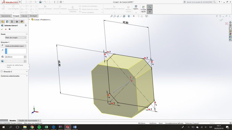
Extrude the body. The measurements are detailed in the image
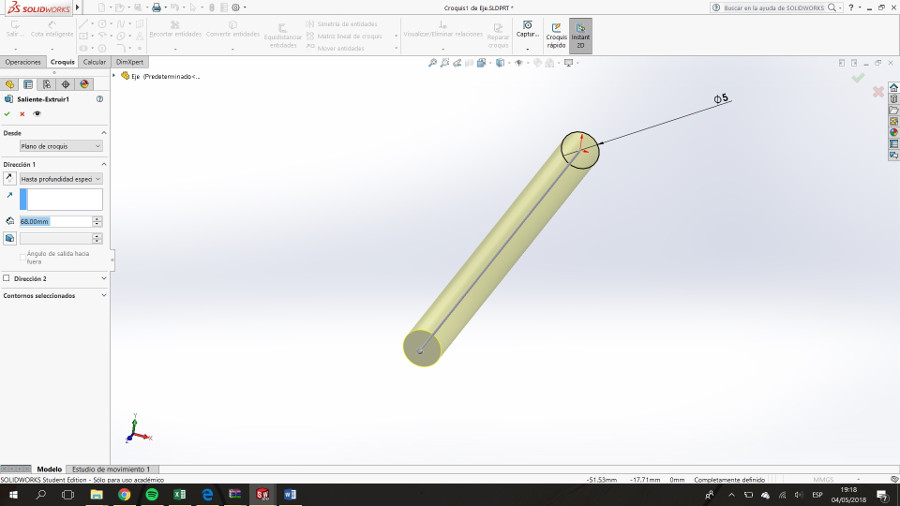
Draw the shaft making an extrusion.
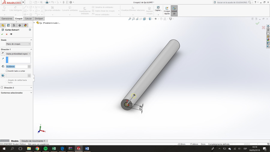
Drill one side of the shaft.
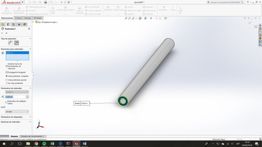
Round it.
Extrude the block that makes up the top.
On the back face lower the interior cavity
It should look like this

On the front face extrude the embossed
Drill the centrer
Drill through the cavity for the shaft
Round edges.
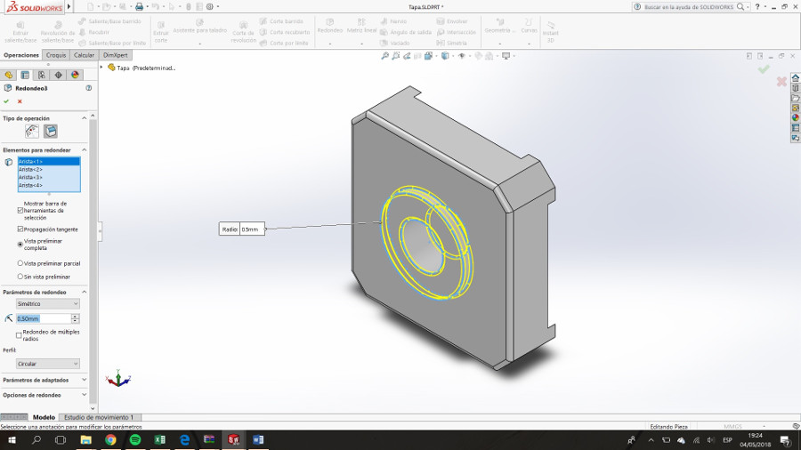
Round edges.
Drill for the hollow of the screws.

Round edges.
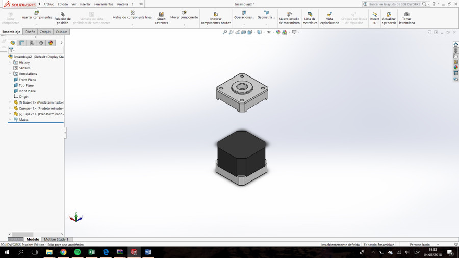
Assembly
It is essential that all parts are stored in the same folder.
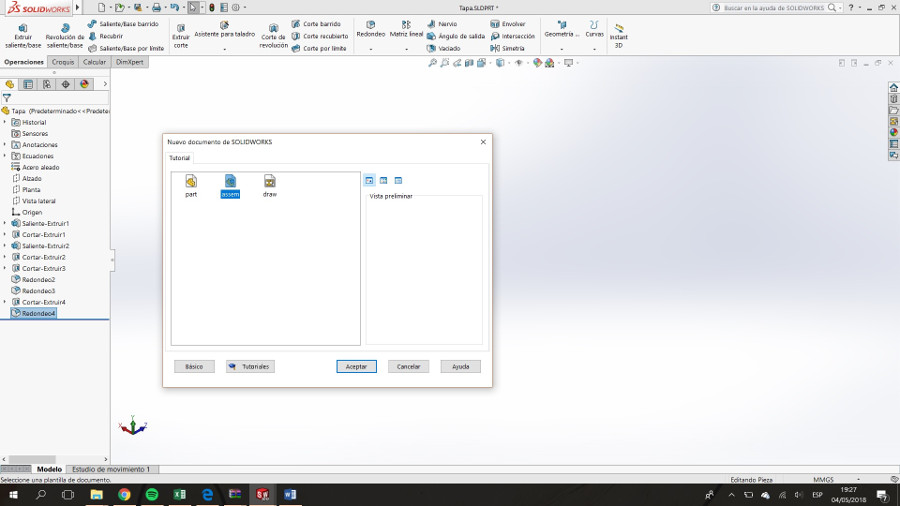
Click on create new file. In the category, we choose assembly. Fundamental to have all engine parts open.
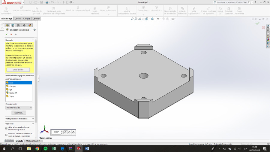
Select the base. On the left is the list of parts.
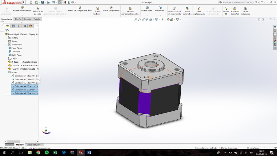
Insert the body
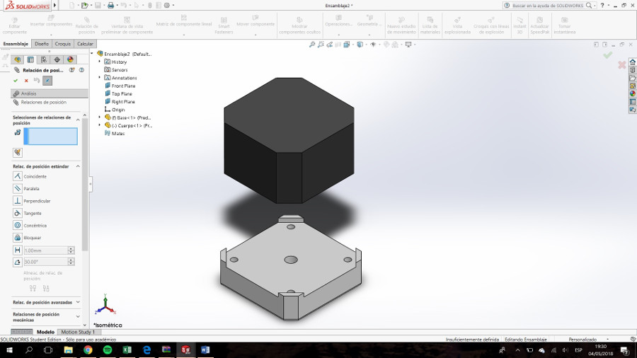
The tool of position link will help us to place the different parts in position.
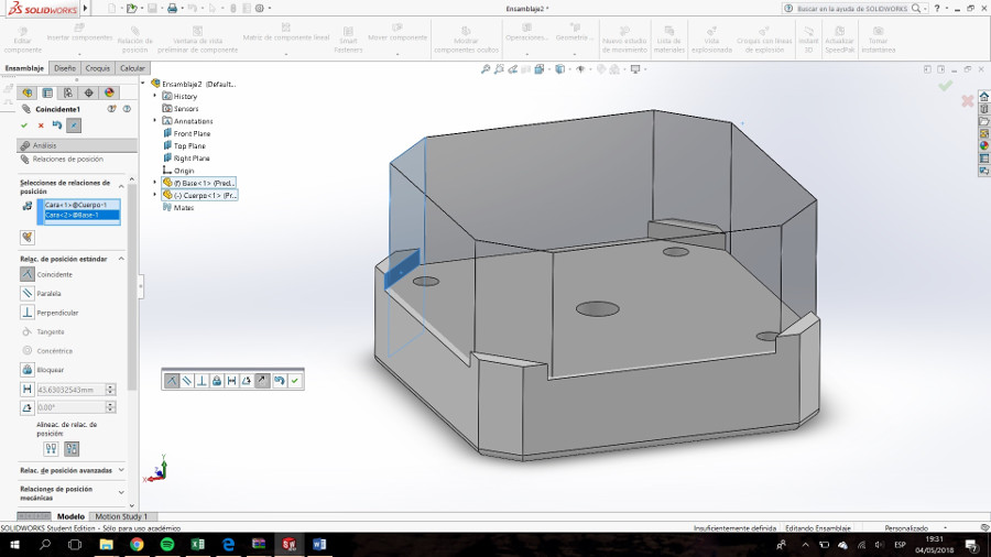
Simply take the edges, faces, planes, etc. And link them to those of another component. In this case we make the chamfers of the body and base coincide.
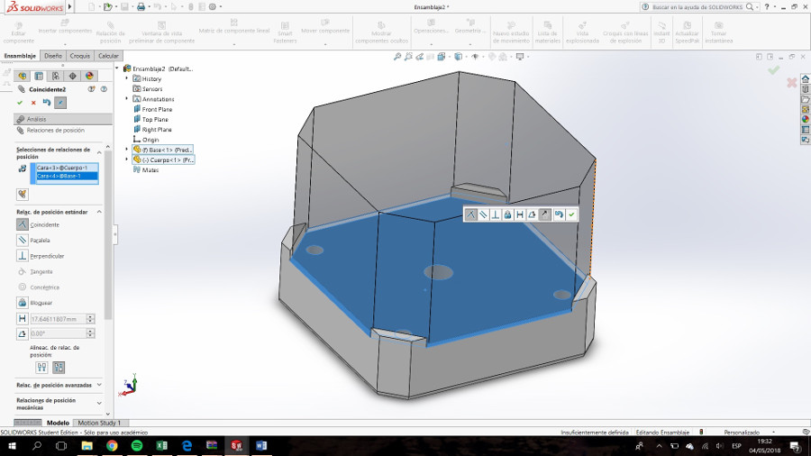
The same with the base of the body and the upper face of the base.
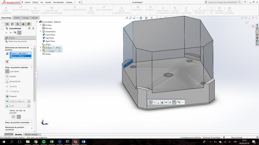
The same with another chanflan.
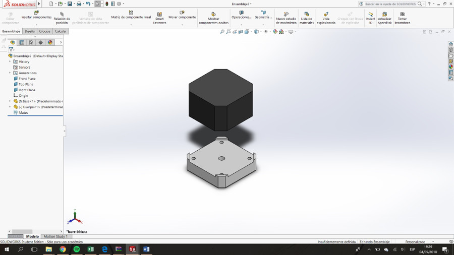
Insert the Top part
Link the Top part and the Body part
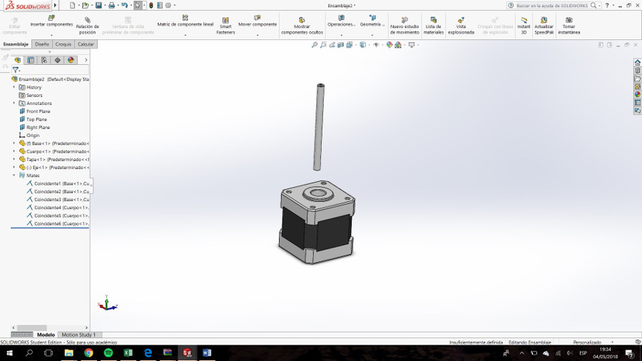
Insert the Axis part
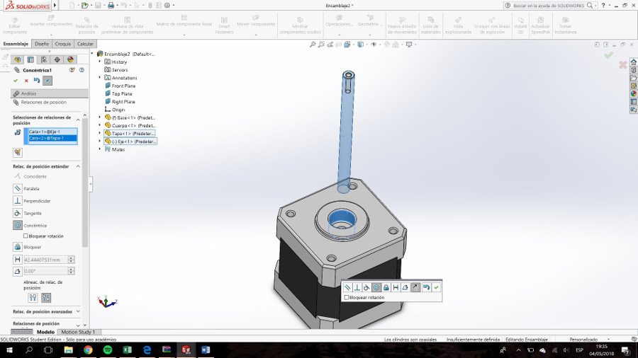
The position of the axis must be concentric with the cavity where it is housed.
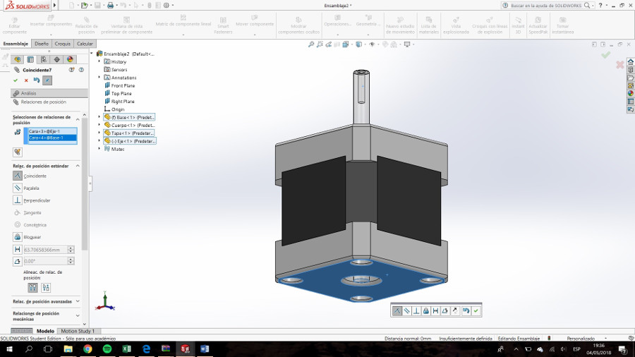
The lower face of the base must be coincident with the other end of the shaft.
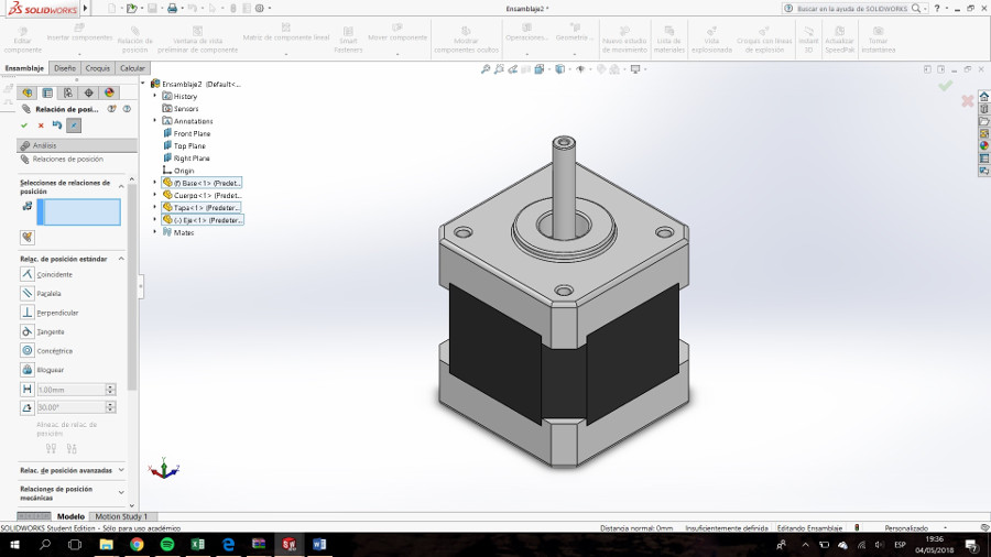
Finished assembly
Conclusion
I have always been a user of Bentley's microstatio, accustomed to civil engineering, mechanical and electrical facilities. Change is hard
The workflow is different and it was no easy to start. Once you get the idea, the workflow it's better, still hard. But I really like that solid works saves all the process and you can go back, rename and restart. Another nice feature is the capabitity to asign variables to diferent elements enabling the design parameterization
It`s important to use the same language, and now on days Solid Work may be the language but You have to pay for the software, I mean, Solidworks is one of the most popular software in the Industry (it's my opinion), and if you want to deal with others, is very possible they work whith Solidworks. It is not a free software, that's why i say we have to pay for it!, This is most powerfull for 3D design and other software. Quick to deploy,to use and simple to administer. People says that simulations in SolidWorks are extremely advanced compared to other CAD systems.
Gimp and Inkscape are powerful tools, also free software.