Fab Academy 2018
by JEAN-BAPTISTE NATALI
jbnatali@gmail.com
daily updates week 03 - computer-aided design
Attending the Fab Academy in Barcelona, I document each week of intense learning as I come across new digital fabrication techniques. This documentation is as much a report of what I do as a reflection on why I do so, and will hopefully guide me back to Oceania to spread and make good use of the knowledge gathered along the path.
--- summary of the assignment ---
objective :
Model (draw, render, animate, simulate, …) a possible final project, and post it on your class page with original 2D and 3D files.
- Evaluate and select 2D and 3D software
- Demonstrate and describe processes used in modelling with 2D and 3D software
what I did :
I designed a seed incubator, as well as a stand for it. This would be a module part of my final project.
- understanding differences between polygonal (mesh) and curve (nurbs) modeling;
- new features and limitation in Fusion 360 : user parameters, sheet metal tool, timeline, online file sharing, constraints, introduction to CAM;
- introduction to FreeCAD, Rhino and Grasshopper (for the latter, see week 16);
- introduction to Inkscape;
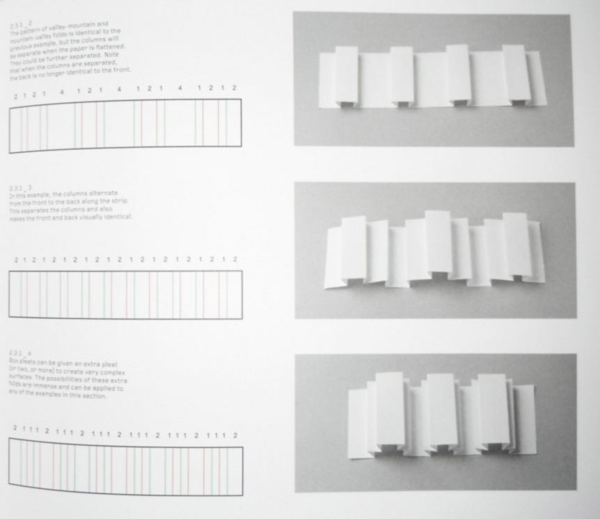
- folding techniques (including curved folding) for planar material and its use in manufacturing;
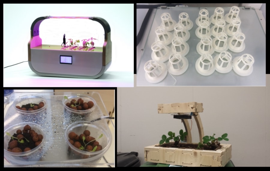
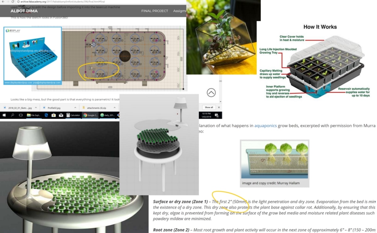
01.02.18 / "Good artists borrow. Great artists steal." P.P. Yeah well, in order to keep the spirits high within the fablab network, I would rather be a little more tactful. I looked for references in the fabacademy archives and found two useful projects. The least I can do is to mention them here. So Haflidi and Albot have been developping incubators of all shapes and sizes, which have been sources of inspiration:
I am designing a simple object with no electronics, ready to be laser cut next week. This design will hopefully be a module which will be added to a bigger structure. This module could become a simple tutorial for laser cutting.
While reading, I pick up useful information about growing plants, which I am interested in since I have little knowledge in it.
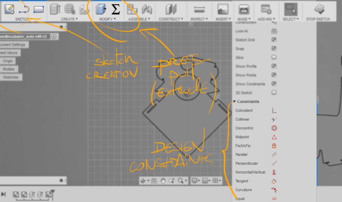
The focus of this week is modeling. Coming from the video game industry, I am used to do direct modeling. Parametric modeling is new to me. I get used to the concept of sketching in 2D first, adding constraints, then specifying dimensions, and finally extruding the surface obtained, turning my sketch into a body :
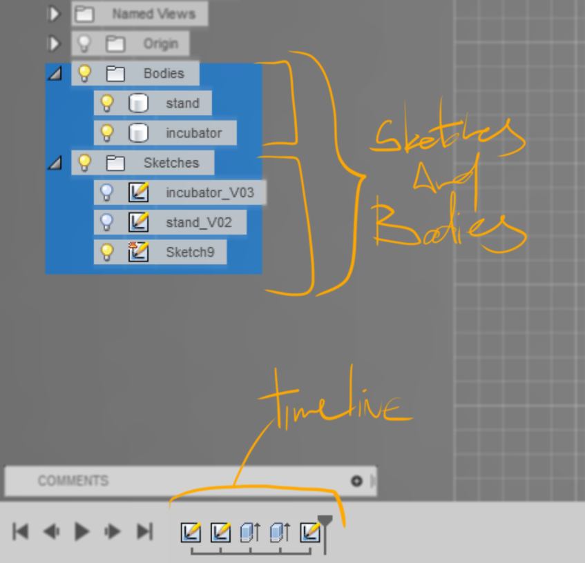
The concept of a timeline is also new to me. Although it is confusing at first ( I am used to sofware like 3dsMax where there is no such thing) it appears as very useful, being able to modify a sketch which then will influence the shape of any object based on it. The fact that sketches and bodies are separated but interrelated is new to me too. The difficult aspect of it is that I am used to have visual feedback, directly looking at and modifying a face of an object. I now have to name sketches and bodies so that connexions between them is obvious :
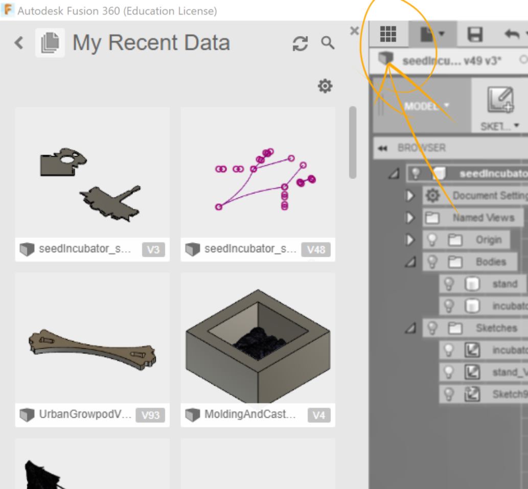
What is really useful in Fusion360 and that I have used in the past is the ability to have a whole team work on a single design, each person designing different components that are all based on an initial design. Everything is stored on the web and accessible for the whole team :
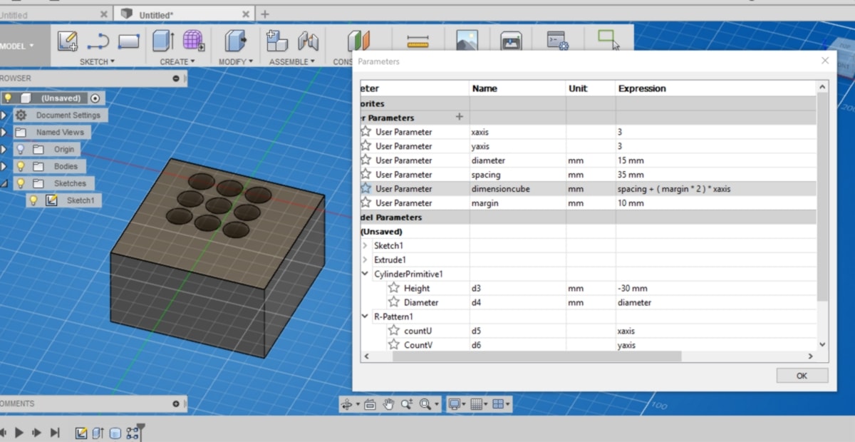
There is also a CAM integrated in the software that I will touch upon later. I am covering tutorials with Fusion360 to complete my understanding of it. What I am really after is something called "user parameters" in Fusion360, to design objects using parameters which can be modified later on :
Discussing with more experienced designers at the lab, I learned that Fusion360 is more approachable and less constraining than other professional softwares such as solidworks or inventor, but is still in its infancy. The simplicity of use comes at a cost, and since the steps required during the construction of a design are not as rigorous, the software is not always able to compute changes when models get too complex. This is discussed in a Youtube video between the designer behind the Wintergatan Marble Machine and Fusion 360 designers.
For the content of the educational platform, since I wish for these tutorials to be used by many labs in the future, with as little restriction as possible, It make sense to design using open-soure, free CAD softwares. However FreeCAD, one of them, is not as intuitive as Fusion360. Rotating around a model feels unatural. It will require some time to get used to it, or get to shape the tool to my preferences. Therefore, for testing purposes this week, I am going to work with fusion360. Between two classes with Ferdinand, I am briefly potting around with the parametric modeling system:
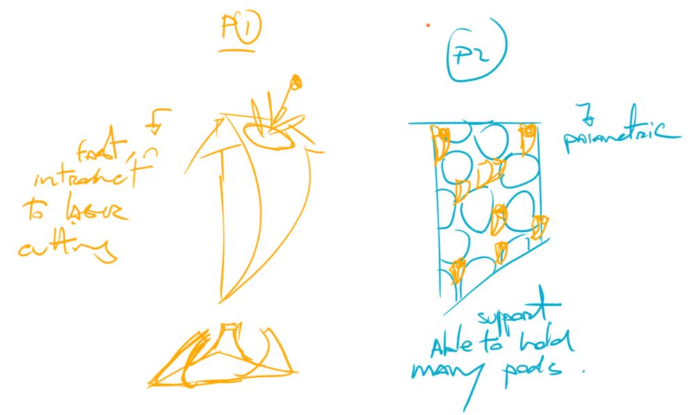
I am interested in parametric design for this model to build a vertical stand which length and high will be parametric. The experience I wish to offer to new members or people discovering the fablab on an open night to make something simple that adds up to a bigger unit. Therefore they are given the opportunity to partake in a communal effort which result is palpable.
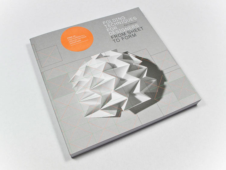
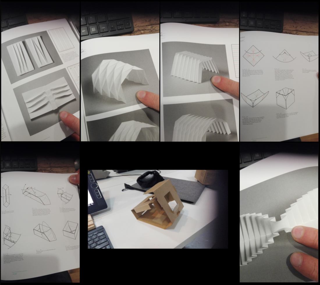
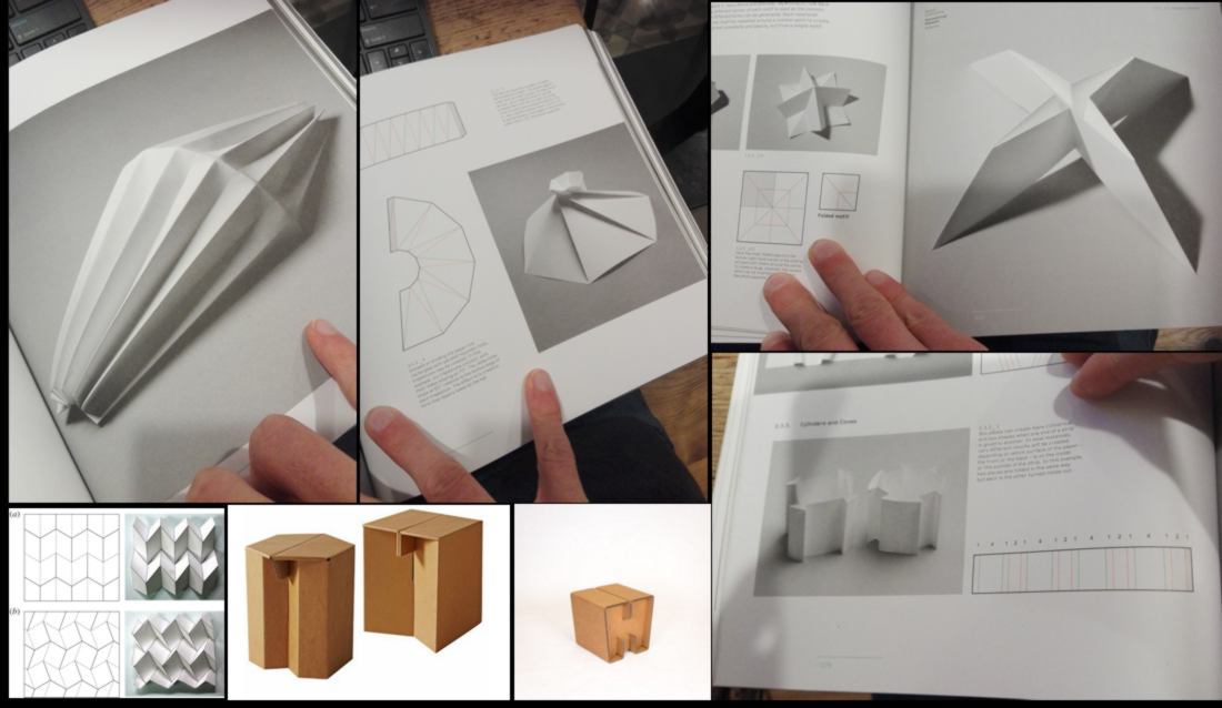
The design of the vertical stand might have to wait for the stand-alone seed incubator to be completed. The next step is to figure out how a 2d shape will turn into a 3d shape. I pick up a book from the shelf called "folding techniques for designers". I am fond of paper folding techniques. I am gathering all sorts of shapes that are either able to provide support, or showing visual appeal in relation with the theme:
In the last two days, the whole class has been chatting about the variety of features and plugins available for CAD softwares, so I would be surprised if there was nothing focused on answering the needs of paper/cardboard designers. And of course there is one in Fusion, but it is a little twisted : it is for metal sheets:
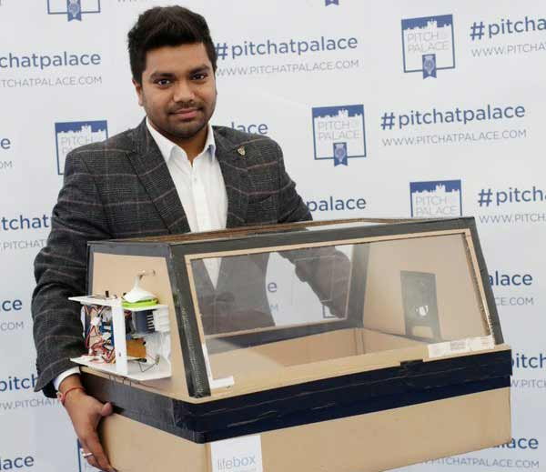
I inadvertenly discover an everyday hero, who has designed a baby-incubator made out of cardboard :
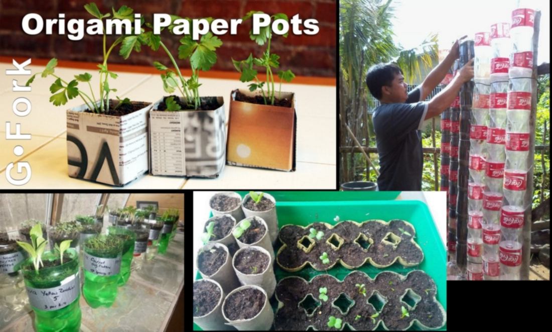
I also bump across the most DIY design for seed incubator, which is really really inspiring:
It makes me wonder WHY people would laser cut their seed incubators. Usually gardeners or apprentice gardeners are happy to have something that does not look amazing. Perhaps, if the incubators are located inside, users might want them to look reasonably good. Also, they might have little space available. Perhaps a vertical seed incubator would make a difference?
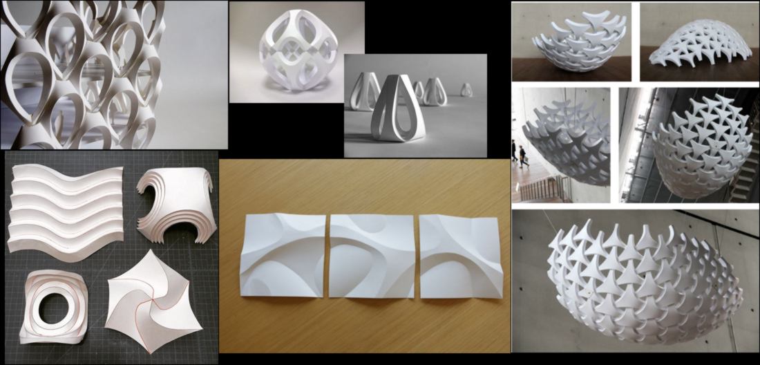
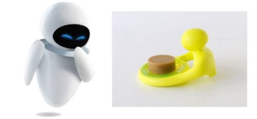
02.02.18 / I keep on looking for options, shapes a little more curvy. I wish to find a shortcut, looking for a design that is pretty much ready to go :
I finally find what I was after:
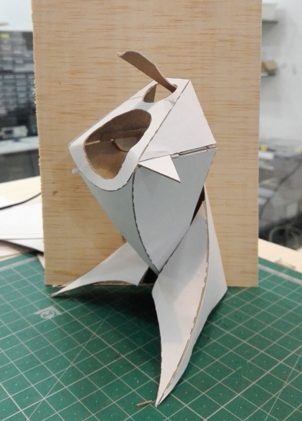
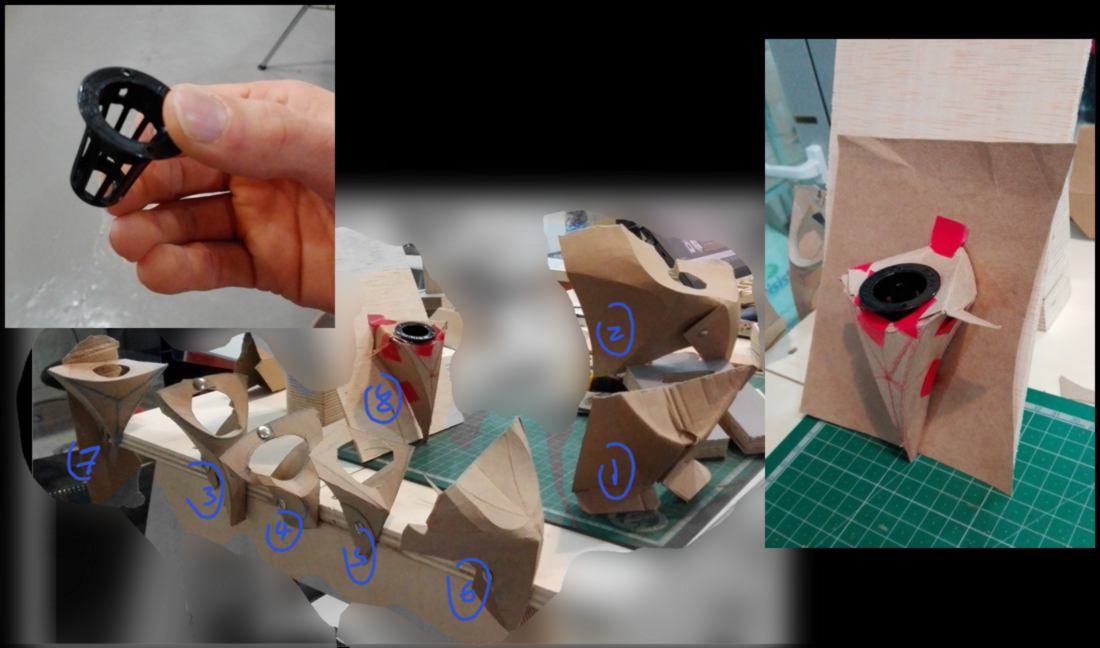
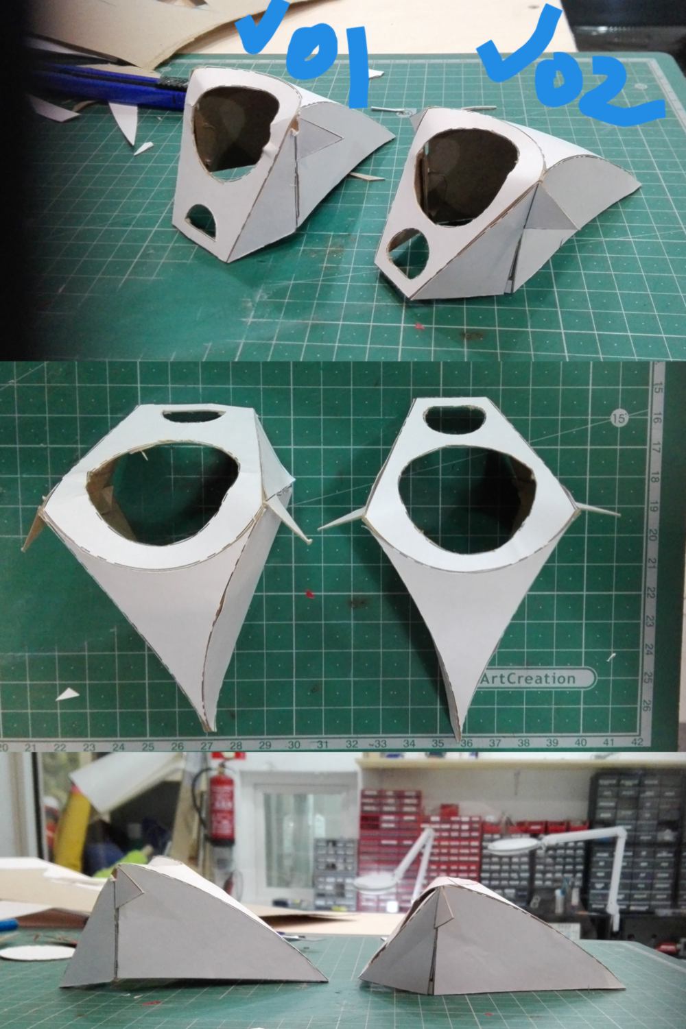
These designs are gorgeous, however, folding with curves rather than straight lines is confusing. I craft a prototype by hand to figure out how this whole thing will work. I am also given a teeny tiny incubator pot for testing purpose:
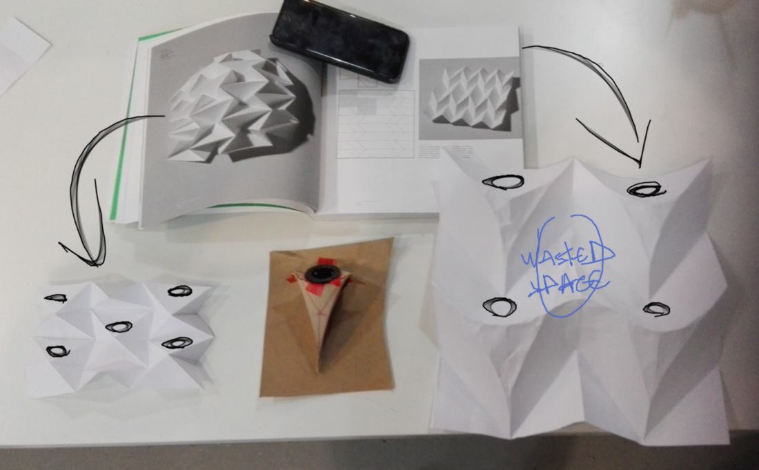
Now I have a shape, I am wondering how to ensure the stand for these incubators will be parametric AND save space. I am pushing for a parametric design to ensure that during a tutorial, learners will think of this feature as useful, therefore looking into the software rather than being content with a pre-cut piece of cardboard:
The design on the left allows more potential pots to be set up. The design on the right has a bit of wasted space right in the middle. I keep it in mind.
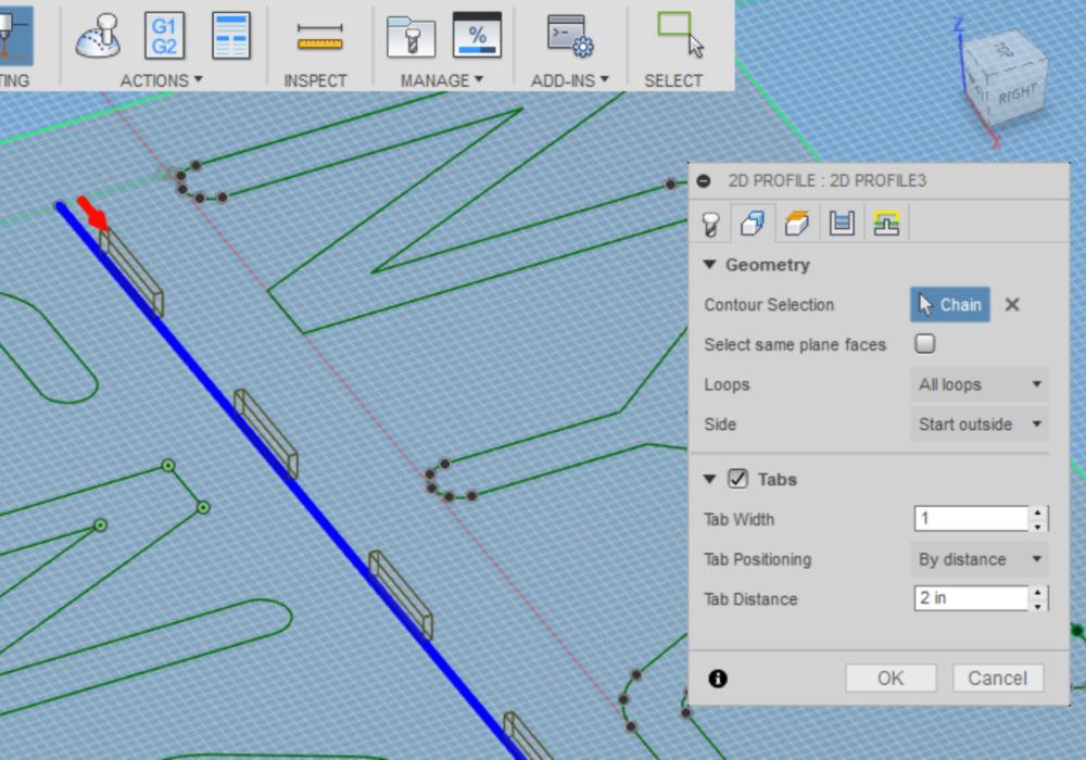
Back to modeling, I have to face a technical dilemna. Now the folding lines are curved rather than straight lines, I cannot use the metal sheet tool in Fusion360 anymore. I will have to draw it as a 2d sketch and get the angles and dimension right. I also need to ensure the folding lines are cut as dashed, not fully. Looking into it, there is an option to add tabs to a laser cut line in the cad mode of fusion360:
It could come handy for next week.
05.02.18 / Back from Paris, I need to wrap things up. As a summary of what needs to be done:
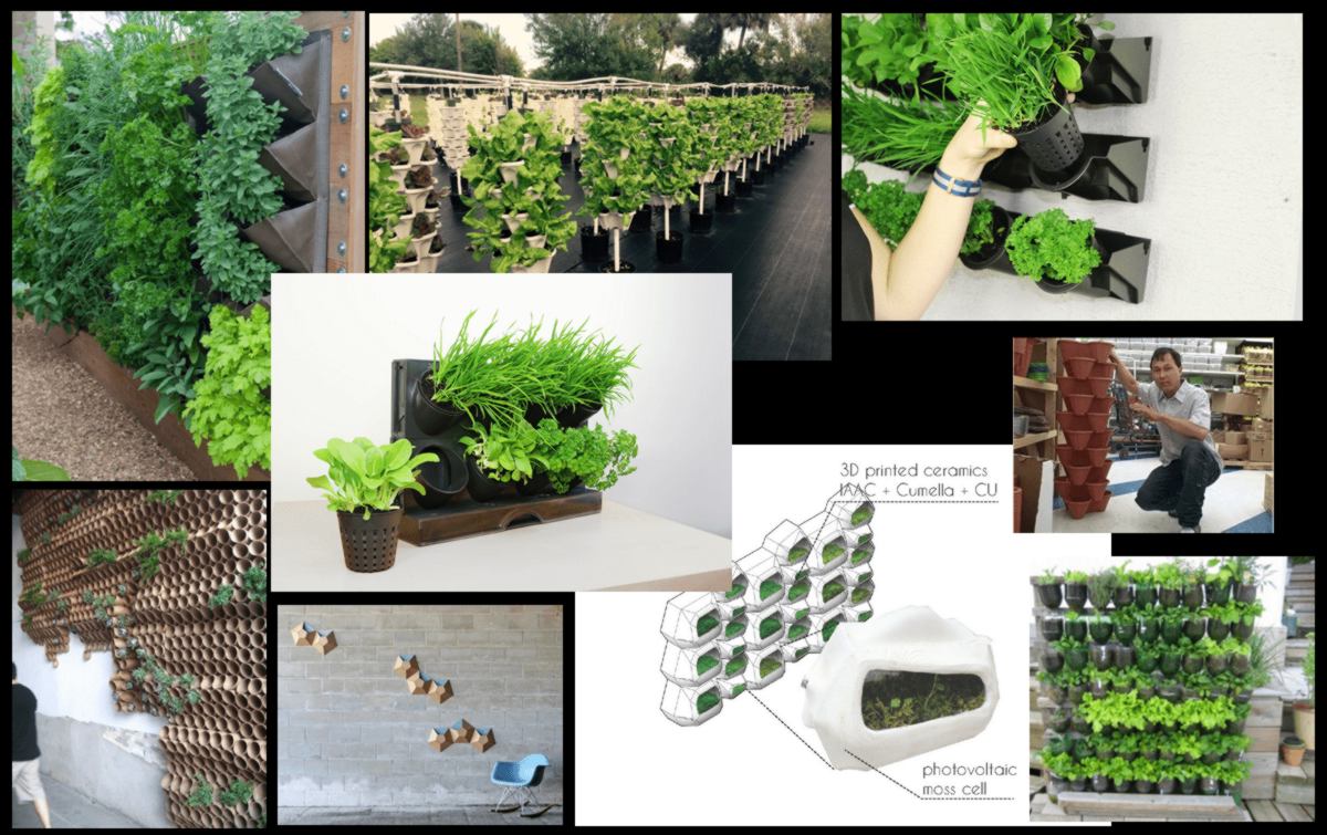
I will solely focus on the design on the left-hand side. I will iterate the shape a little, insipired by the following designs. Making container to host one plant at a time is not effective, and therefore efficiency will not be the point of this design. The idea is that, to make it worthwhile, it must look small and adorable:
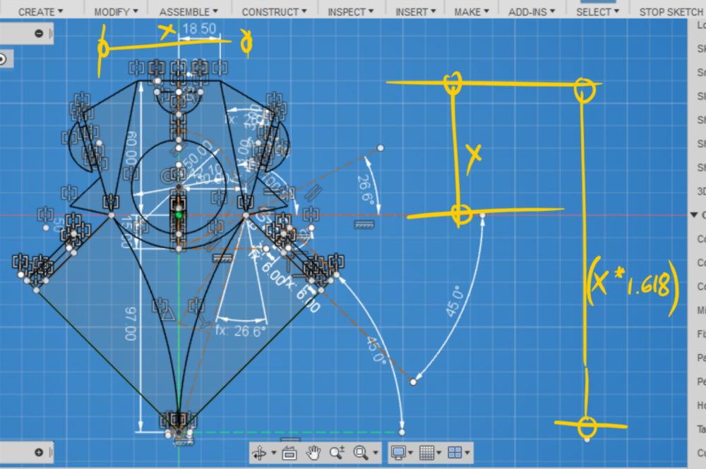
I have added one user parameter called "thickness_material" to adjust the size of the tabs according to the thickness of the material chosen, which is very likely to vary since materials will come out of scrap pieces of cardboard. Also, out of curiosity, I have adjusted my initial design so that the general proportions of this design respect the golden number:
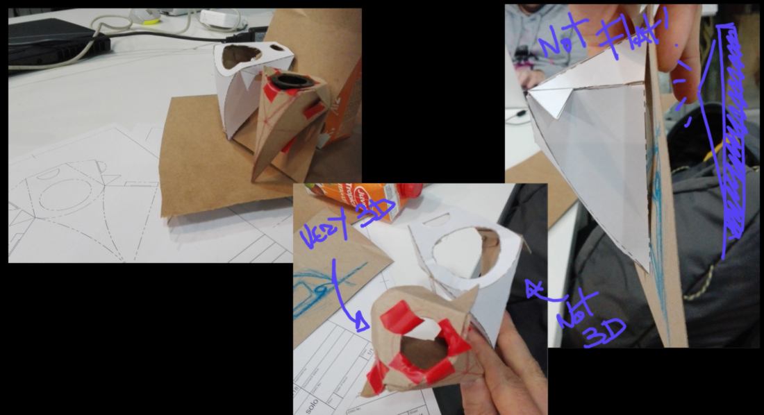
From a technical perspective, Fusion360 is giving me a hard time. When modifying the original design again and again, Fusion360 starts slowing down and crashed a few times. To remedy to that I created a new sketch based on my original one and it now works fine. I have (2D) printed and put together a model. I am happy about the tabs, it holds very well, however I need to make the width of the gap twice longer since I have to fold the cardboard to fit it in. Other things must be corrected : the model does not have a flat back, and the top part of the shape has lost some 3D "feel", which makes it looks a little heavier and clunky.
Over the last few days we have covered many 2D, 3D free modeling and CAD softwares in class, and I am pleased to see there are many open source options available : FreeCAD, OpenSCAD, Blender, Antimony (which makes a lot of sense to me, although I don't pretend to understand the mathematic behind it). I am going to intiate a slow shift towards using these tools over the next few weeks.
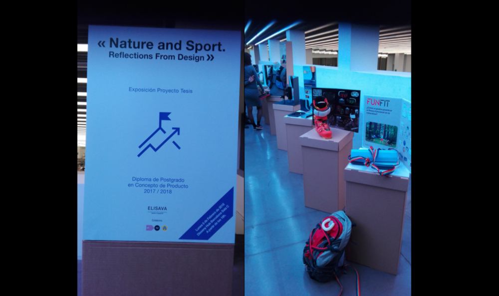
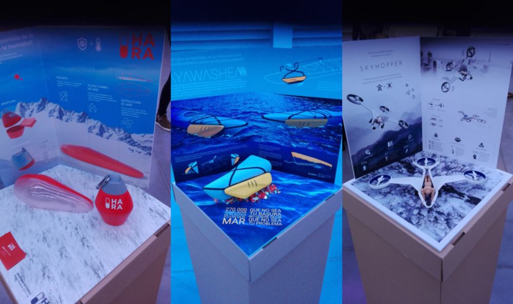
On my way back home I bump into a student exhibition about design for outdoor sport. Most students designed hi-tech objects answering the needs of city-dwellers in need of some fresh air. A student however, designed an object to solve a pollution problem, designing a container attached to the front of canoe, collecting plastic bottles as users gets her/his/their fix of adrenaline :
06.02.18 / Within a single minute, Ferdi and Anastasia rocked my world by giving me new keyword to look into, related to curved-lines folding technique : "Robofold". I am now aware that once googled, this will send me on a week-long trip towards a world of new shapes and softwares to expand on this technique :
For now I am running out of time so I am going to focus on finishing the seed incubator, modifying the issues identified on Friday:
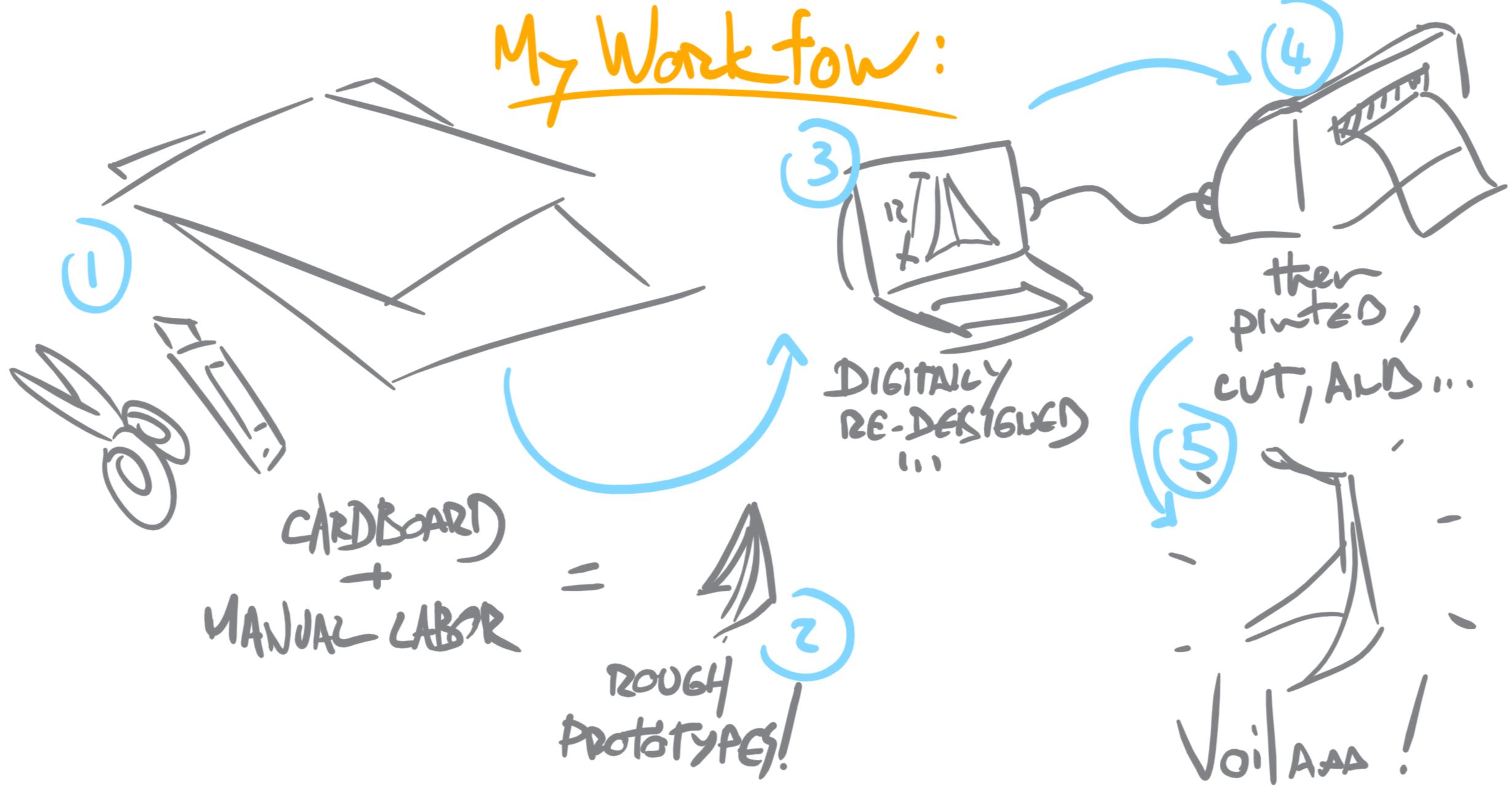
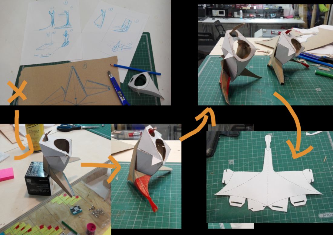
I also need to make a stand for it. The process is identical : I draw something quickly, then shape a prototype by cutting and sticking together some thick paper. I keep on modifying it to test different options. Once the model cannot take any other modifications, I create another copy, and modify it again, until I get what I want. Only then I draft the 2d model digitally, print it out, and fold it. I might keep on iterating the model for a bit, modifying the digital version, printing and folding it again and again, until the prototype is functional.
The difficulty with this model is to fold the material along curved rather than straight lines. Calculating the projected angle and length of different parts is a little more tedious. With a cardboard model though, I get away with approximations.
I am not particularly pleasedby the shape of the stand. I am dubious people would use something which looks that "edgy" and futuristic in their kitchen for daily use. If I had to design it again, I would stick with a very simple "pot" shaped design, or something rounder, like a nut or a shell:
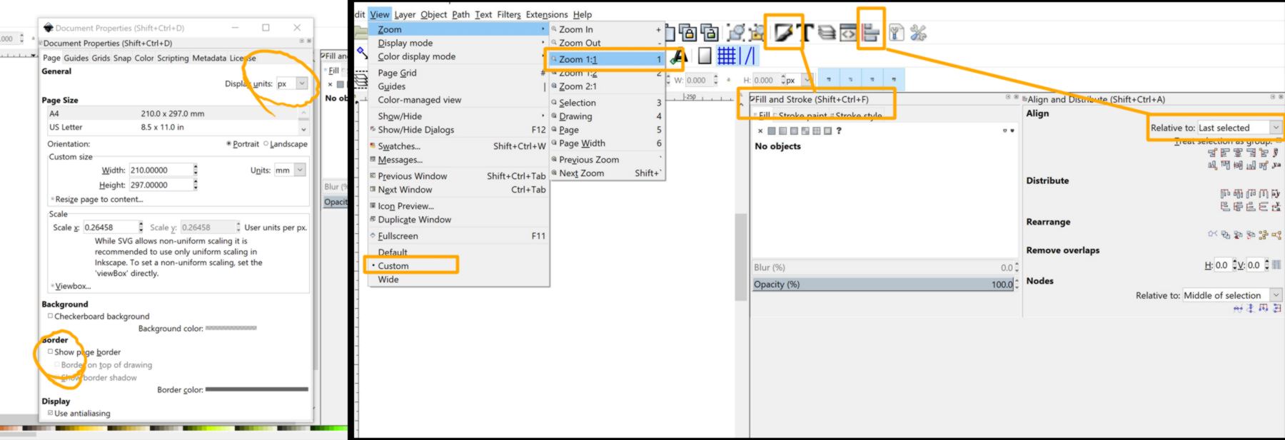
07.05.18 - Late addition!!! / here is an Inkscape tutorial that I will follow to complement my learning this week. I have selected this tutorial because it is fairly recent so the location of icons in the tutorial should match mine. This particular tutorial covers logo creation. This is usually the kind of job - logo creation, icon creation - that I will use inkscape for : no parametric design needed, just a clean vector-based drawing which can adapt to all sizes.
First I set up my document property so I do not have defined borders, and use pixels as a unit. I set up my view as "custom", change the zoom for real-size (1:1), change my alignment setup to "last selected", and display the fill and stroke window.
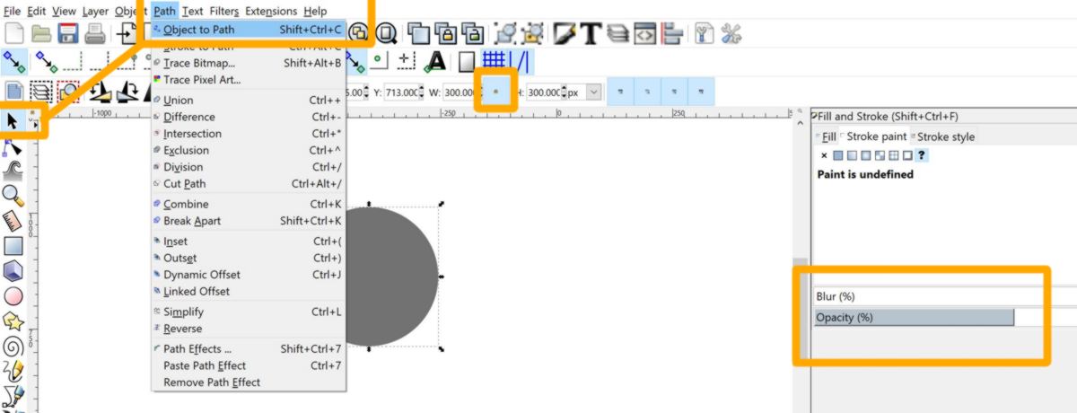
Now I start drawing, using ctrl+shift to draw a perfect circle, then convert this object into a path, drop the opacity to about 50 percent, and change its size to 300px using the lock to lock the width/length ratio of the object before resizing it.
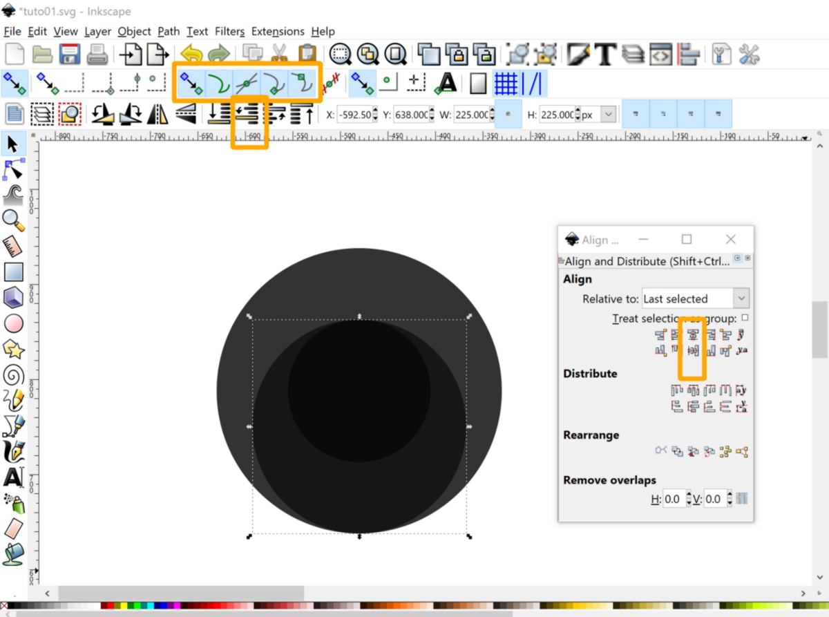
I then duplicate the circle, resize it and align it with the other one using the align tools. I then switch on snap tools for paths, duplicate the small circle and align the bottom to the bottom of the large circle, then drop it by one step using the "one step down" button.That will allow me to select the smaller circle and modify its color in the next step.
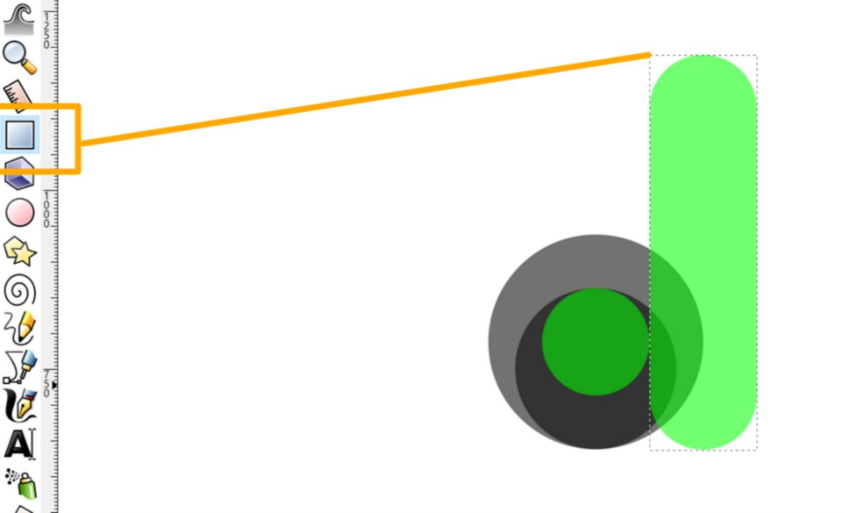
I then create a rectangle which will represent the right side of the letter and align it with the right-hand side of the smaller circle. I then chamfer the corner using the rectangle tool and convert the rectangle into a path.
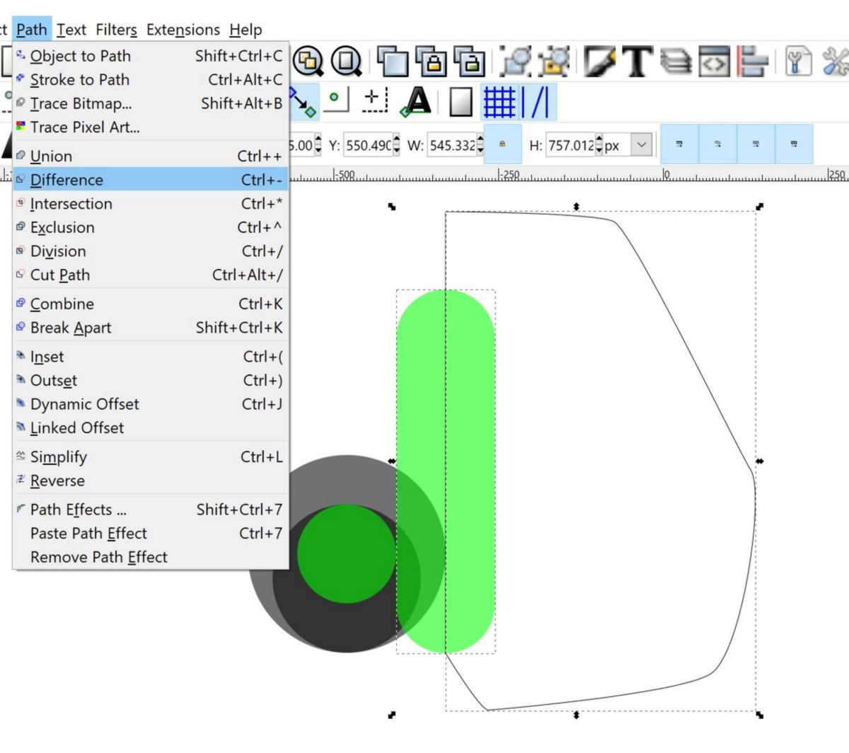
I then cut the rectangle by drawing another path with the bezier tool, and use the "difference" function in the path tab :
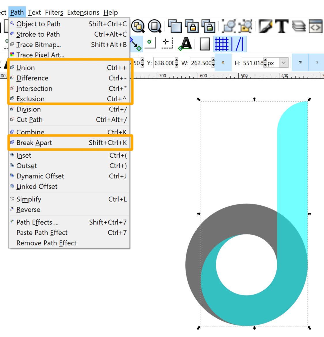
by using the function available in the path tab, I am going to cut, add and connect different paths together :
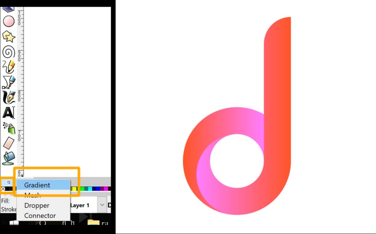
This gymnastic of duplicating then selecting and modifying shapes takes a bit to get used to, but it comes handy. I then color each shape using the gradient tool (a bit harder to find on my screen, smaller than average). And here we have a d-shaped logo with a 3d-render to it!
 Fab Academy 2018
by JEAN-BAPTISTE NATALI
jbnatali@gmail.com
Fab Academy 2018
by JEAN-BAPTISTE NATALI
jbnatali@gmail.com
