Attending the Fab Academy in Barcelona, I document each week of intense learning as I come across new digital fabrication techniques.
This documentation is as much a report of what I do as a reflection on why I do so, and will hopefully guide me back to Oceania to spread and make good use of the knowledge gathered along the path.
--- summary of the assignment ---
Laser Cutting : objective :
make lasercutter test part(s), varying slot dimensions using parametric functions, testing your laser kerf & cutting settings (group project). Also, design, make, and document a parametric press-fit construction kit, accounting for the lasercutter kerf, which can be assembled in multiple ways.
Vinyl Cutting : objective :
There is no specific project that is focussed on this very useful tool. There are a range of ways you might utilise it throughout the programme, or your local instructor may set a specific project. You might make, stickers, flexible circuit boards, a textured surface/relief pattern, screenprint resists/stencils.
what I did :
About laser cutting : I made a camera stand. I also reused the laser cutter to iterate on my final project, make a machine during the machine making assignment and in many other occasions during the Fab Academy.
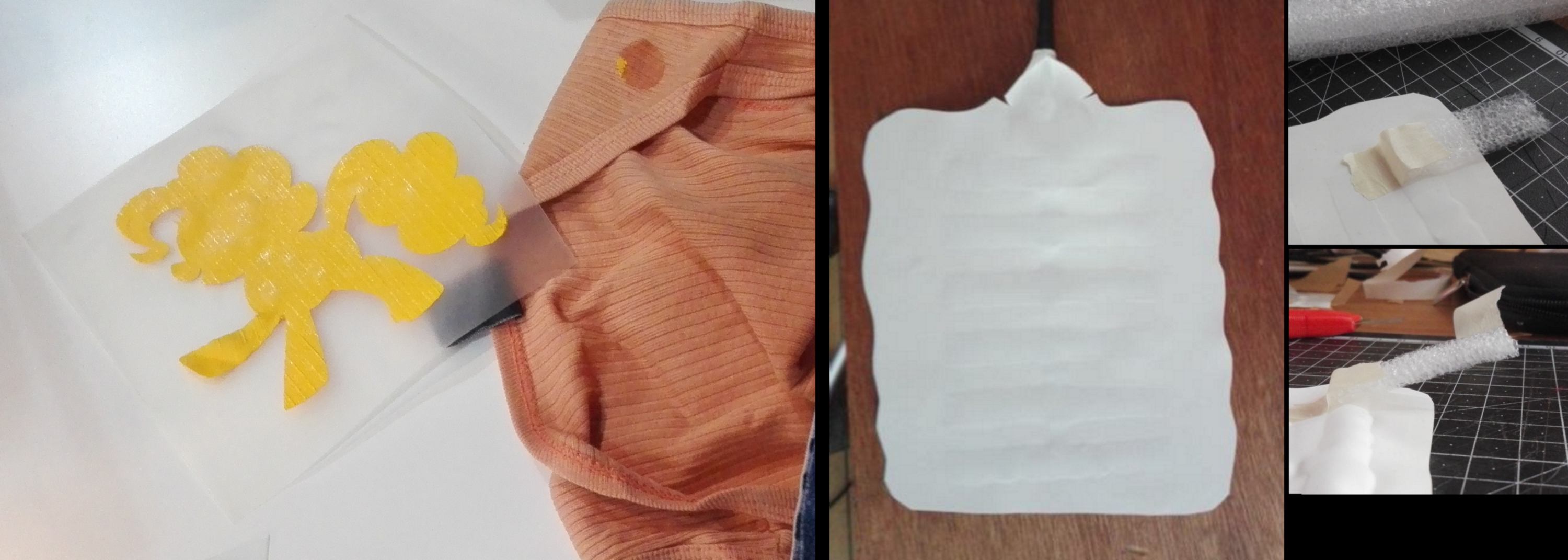
About vinyl cutting : I made a design for a tshirt. During the wildcard week, I also designed air channels for an object actuated by air pressure.
download :
Learning outcomes :
Notes to evaluators :
07.02.18 / I am beginning the week by a cleanup of the website, updating it, adding a menu, getting rid of the dissociation between daily and weekly reviews and proofreading the last week of documentation.
I have a rough idea about how to add a menu, however I still need building blocks to put it together. By going on www.w3schools.com, I find a tutorial to create a fixed object, then add to it another tutorial to create a navigation bar, and finally add a last one to create a drop-down menu. I copy-paste the code, then edit it until it works, looking for descriptions of the functions used. Finally, I get rid of everything that is not required, in this case the background color, additional alignments etc. This approach has the benefit of forcing me to understand what actually happens as well as increasing the probability to end up with a functional feature by the end of the day.
Once home, an exciting news is awaiting. A friend developing "the Commons", the outdoor space where I plan to set up the lab, contacts me to ask for some help to write a funding application. A telecom company called Spark will be soon donating NZD 1.000.000 to community projects focused on digital learning, education and community outcome. I read the description of the requirement for this application and begin to draft some content.
Before that though, I am going to contact Laura Cipriani, a current fab academy student at OpenDot, Milan. Her project is similar to mine and a conversation would be most beneficial. Her approach is slightly different from mine, however her project also requires to produce educational content. Finally her project is connected to the Global Humanitarian Lab. I remember having dinner with some of them last year in Chile and I am looking forward to see them moving ahead.
08.02.18 / The website is very time demanding, proofreading requires time every day, but soon I will feel comfortable sharing the link to this website with others.
I look into preparing a CAM file for the laser cutting session this afternoon, watching fusion360 tutorials and going through some documentation :
It seems people use a vector sofware to prepare the paths, Inkscape even has a plugin able to generate g-code. I am trying both options.
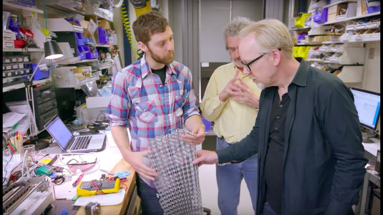
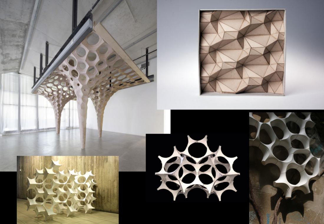
It reminds me of a very inspiring documentary about advanced paper-folding techniques:
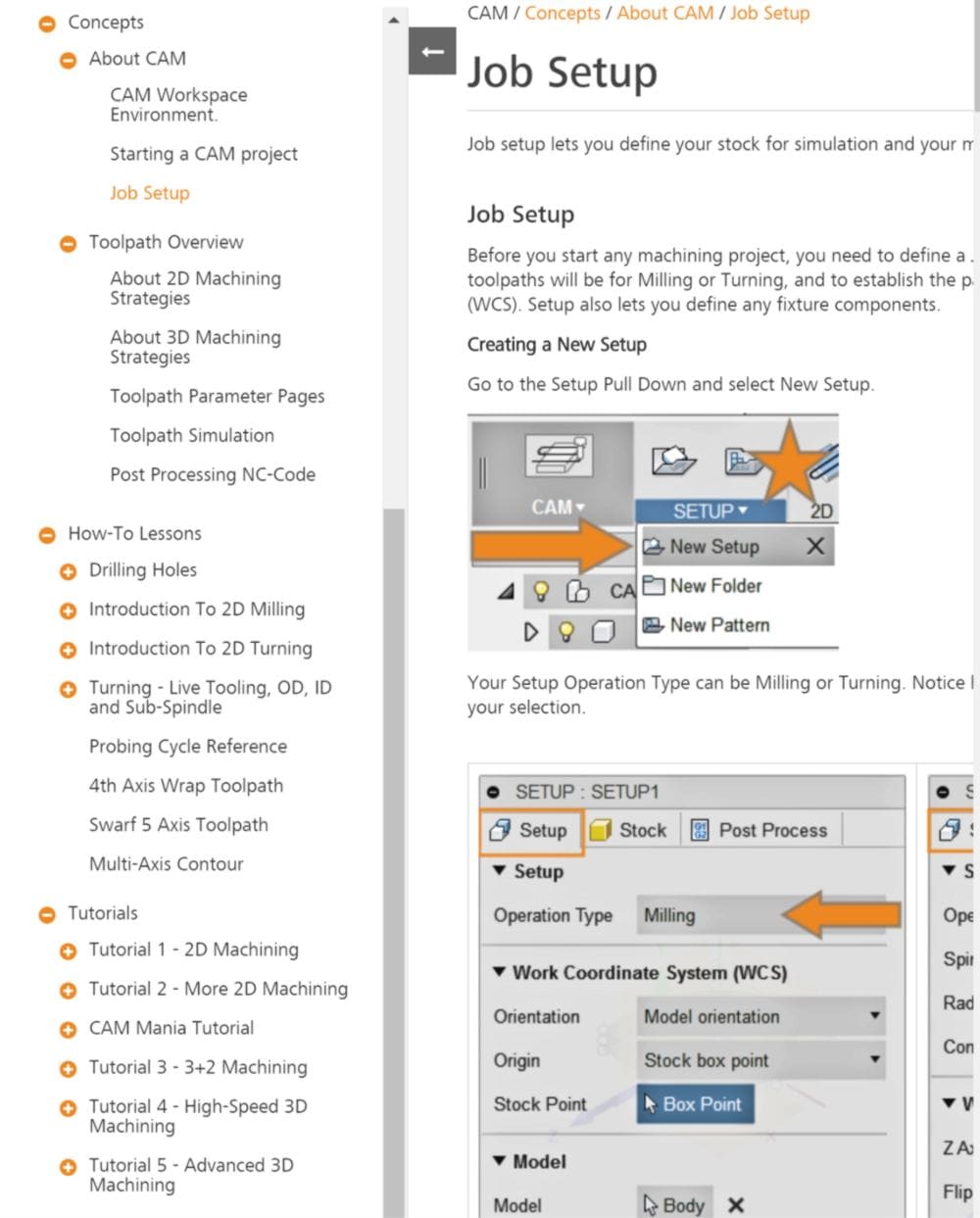
At first, I get lost in the range of option that Fusion360 offers, but I find a very useful tutorial and extra documentation:
On Fusion360, the process is a little laborious, and the toolpath refuses to be created when adding sideways compensations. By getting rid of sideway compensations, I get a path for the outer edge. I then need another path to cut following dashes for the folding lines. I think about creating a second path with tabs, based on a projection of the folding lines. The reason for using a projection rather than a copy of the model is to be able to modify it afterwards and keep my CAM operational.
However Fusion crashes when calculating this path. Meanwhile, in Inkscape, I get to the result I am after in a few minutes, getting a .svg file.
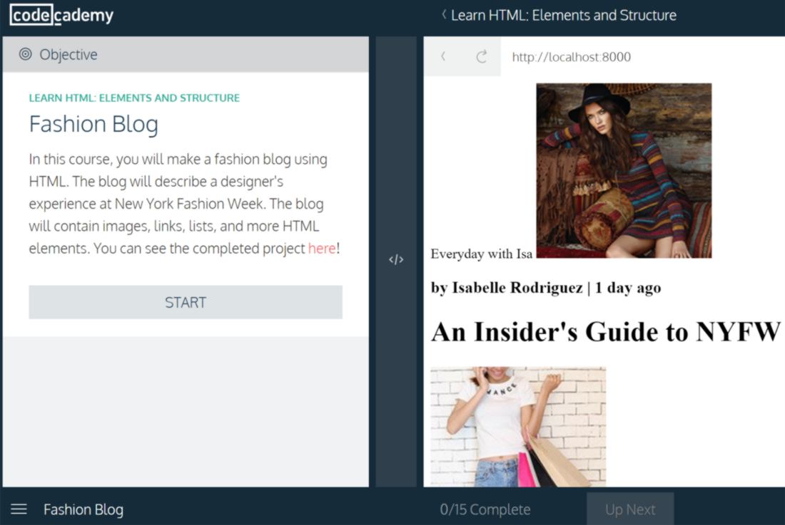
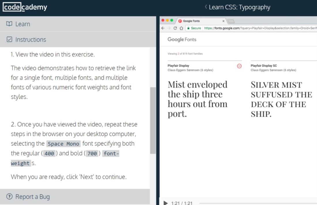
This afternoon, we are covering all about laser and vinyl cutting. With each new week, a theme is added and I feel short on time to develop the final project I have pitched. The amount of new information is enormous. I feel the need to reinforce my weak understanding in subjects I have already visited : web development, kirigami, 3d modelling. I go back to code academy to cover web development projects and tutorials in html and css:
09.02.18 / I go over the many links on the local documentation of the fab academy Barcelona webpage, gathering new information and getting inspired:
We are now able to access the laser cutter. Out of the many available at Fab lab Barcelona, we begin our work on a Trotec 400 which manual can be found here . Amongst its many features, it offers a large working surface (1000x600) which is game-changing.
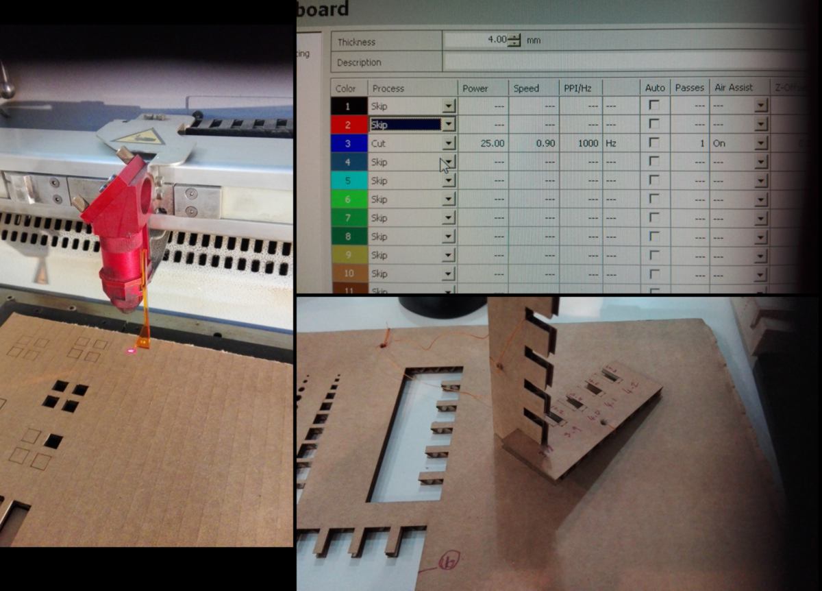
During our group assignment, we run several tests. Files are imported in Rhino, paths are assigned a color according to the type of cut we whish to run, and the file is sent to the Trotec proprietary software to handle communication with the Laser cutter. We define the cutting properties there, and let the machine do the job.
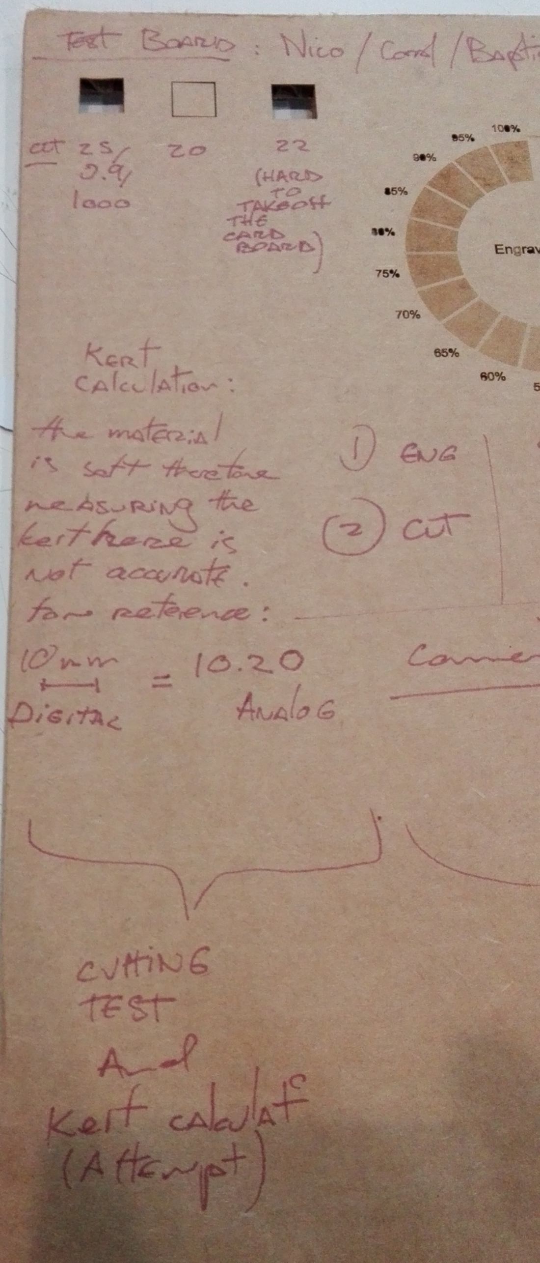
First we create a test board:
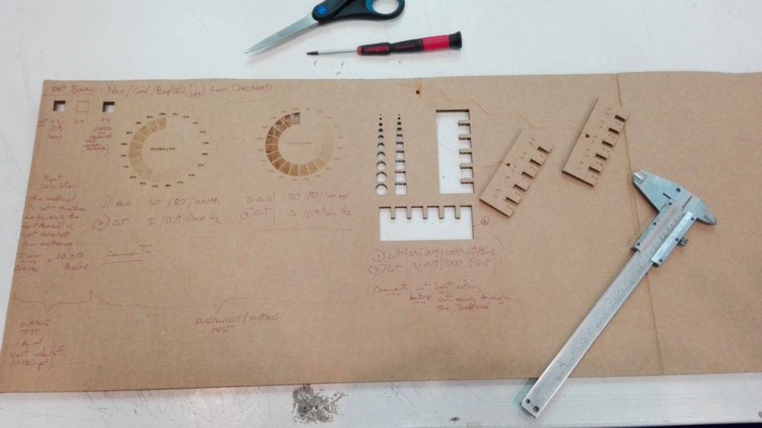
In the first step, We define the amount of power required to cut through the material. Cardboard is a soft material, therefore we postpone the measurement of the kerf. Plywood will offer a much more precise measurement.
We then calibrate the raster mode. As the laser moves slowly downwards, it sweeps over the material from left to right and modifies the power generated by the laser according to the lightness of the shade in the file.
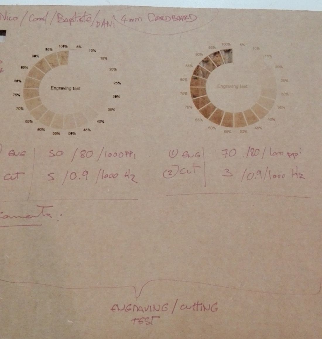
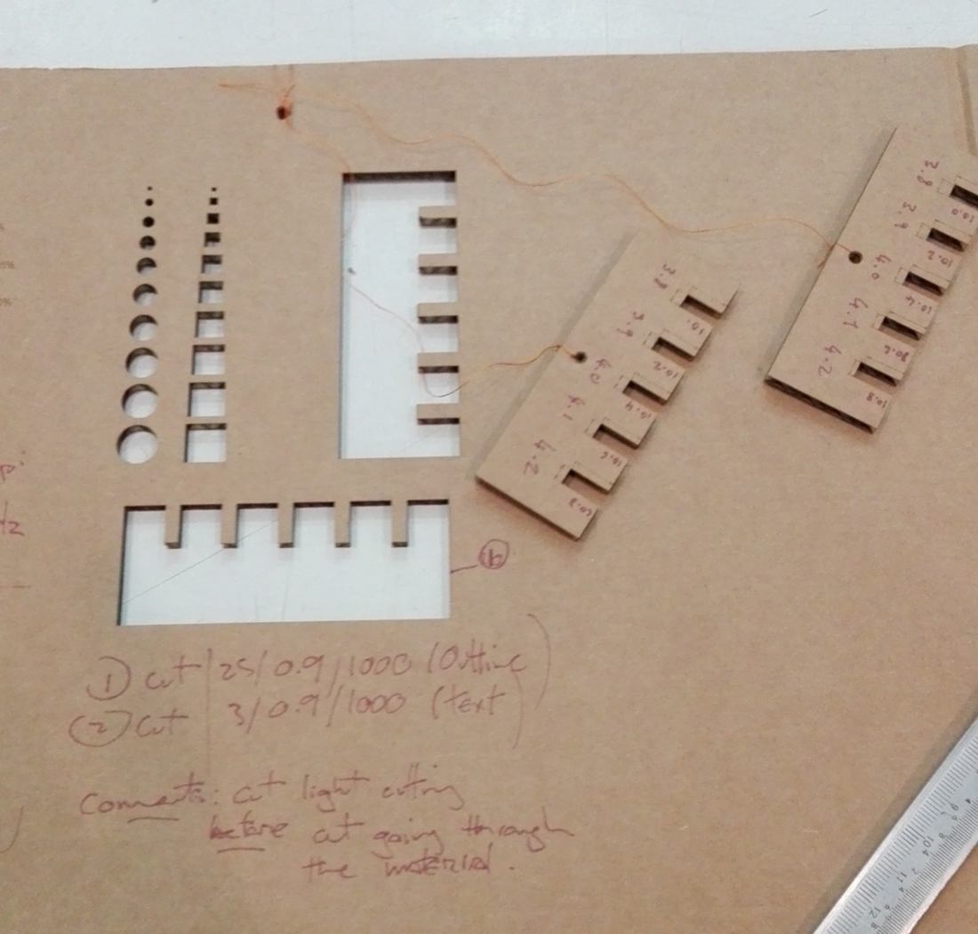
Finally, we test different sizes for press-fit connections.. This will help us select which measurement is most likely to provide solid attachment between pieces for our kit.
Since the beginning of the course, we, as a class, have not had the chance to mingle and get to know each other. This afternoon, we are all going to the green lab in Valldaura to relax and eat some local delicacies, beaten up by a surprisingly cold wind. It is really nice.
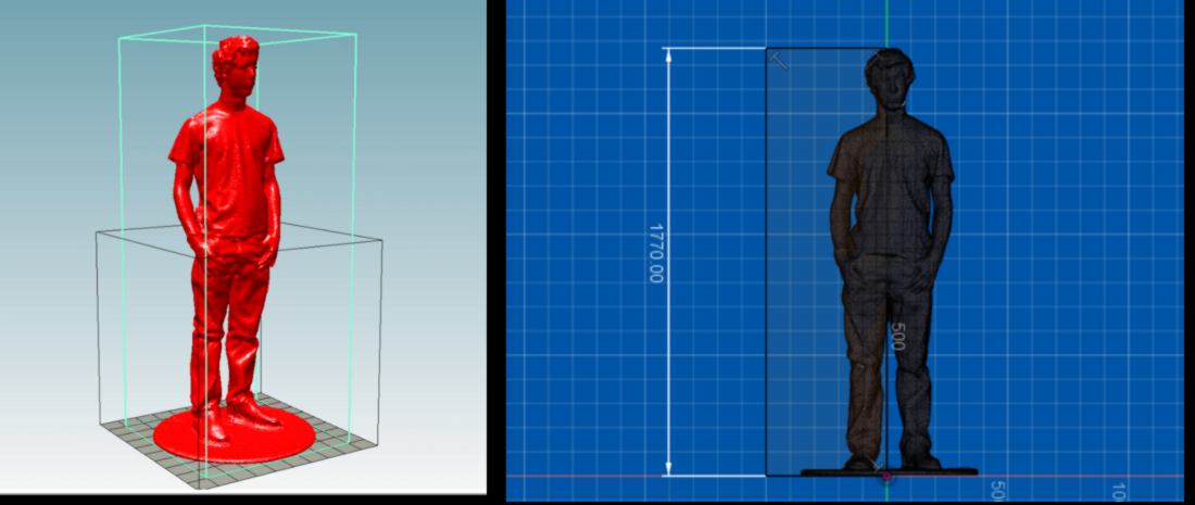
Back home I decide to test out Slicer in Fusion 360. For future reduced-scale models, I wish to have a human standing next to it, providing a sense of scale. I think that a cardboard object is a way to use little material to achieve that result, compared to a 3d printed model.
On Thingiverse, I find an elegant model and download it. In fusion360, I rescale it to the average European male size.
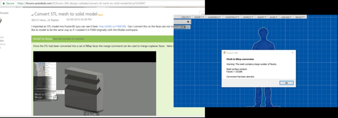
When trying to use Slicer into Fusion 360, the cardboard model refuses to be generated. It seems that Slicer in Fusion360 only accept solid body, and currently my object is a mesh. Helped by a tutorial, I attempt to convert the model, but the large number of faces of the object makes the conversion impossible. The model is a raw 3D scan and therefore it is very high definition.
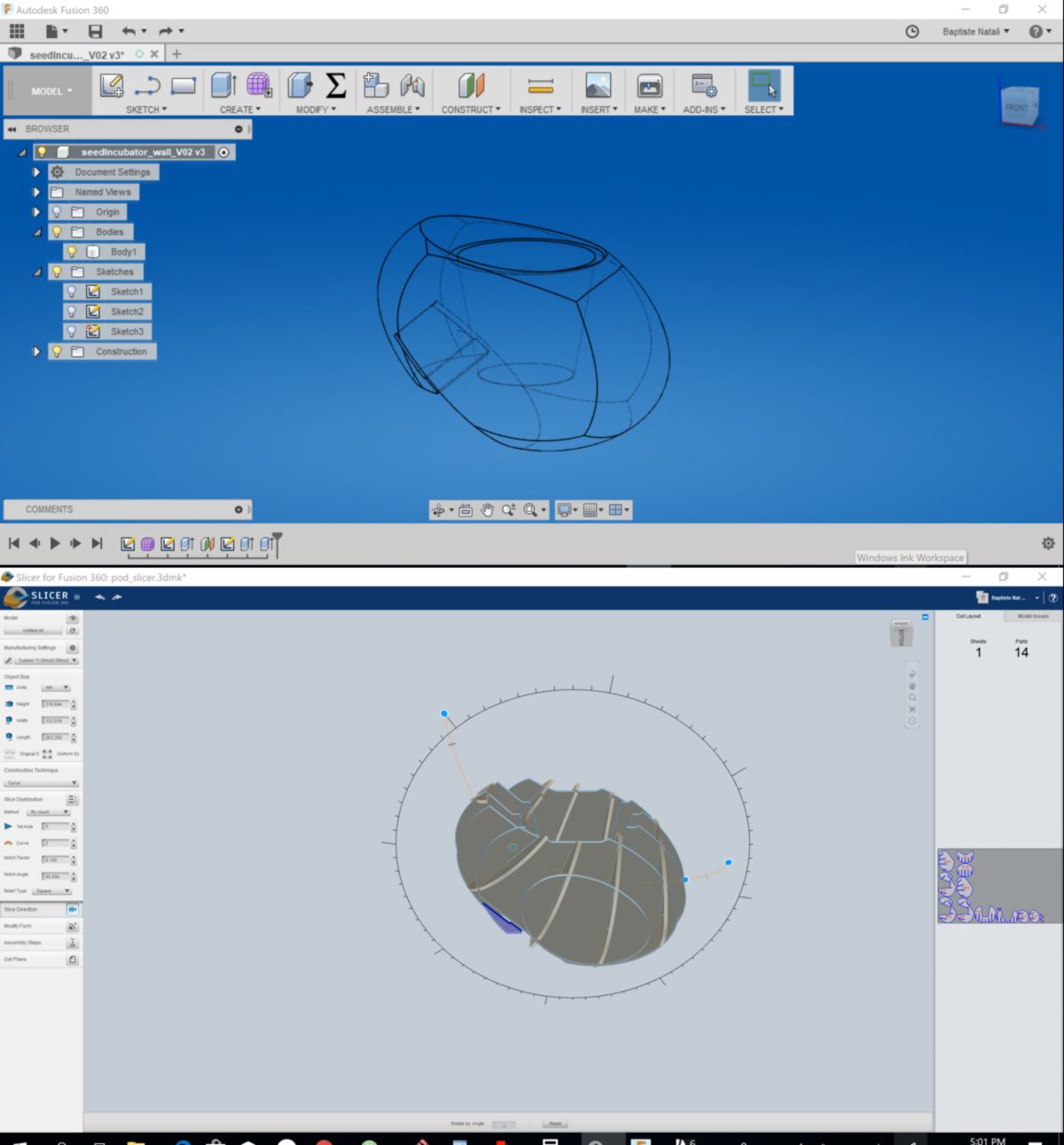
Luckily once Slicer is installed for Fusion 360, it also works as a stand-alone, and accepts to load my model. I wish to work in a scale of 1:3, therefore I set up the scale of the model to 600mm.
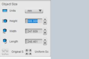
I set up the size of the material to be cut. I adjust it according to the size of the laser cutter, a speedy 400.
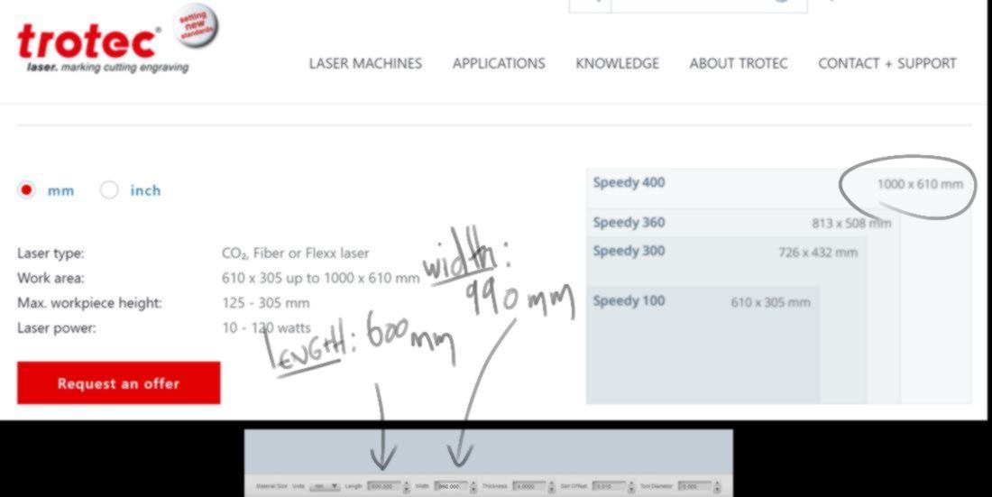
I adjust the orientation and number of slices to get a model that is recognisable but use as little material as possible. In my first attempt however, the model take pretty much the entire surface of the sheet. I wish to use this sheet for many other tests, So I reduce the size of the model to 295mm. I now work in scale 1:6.
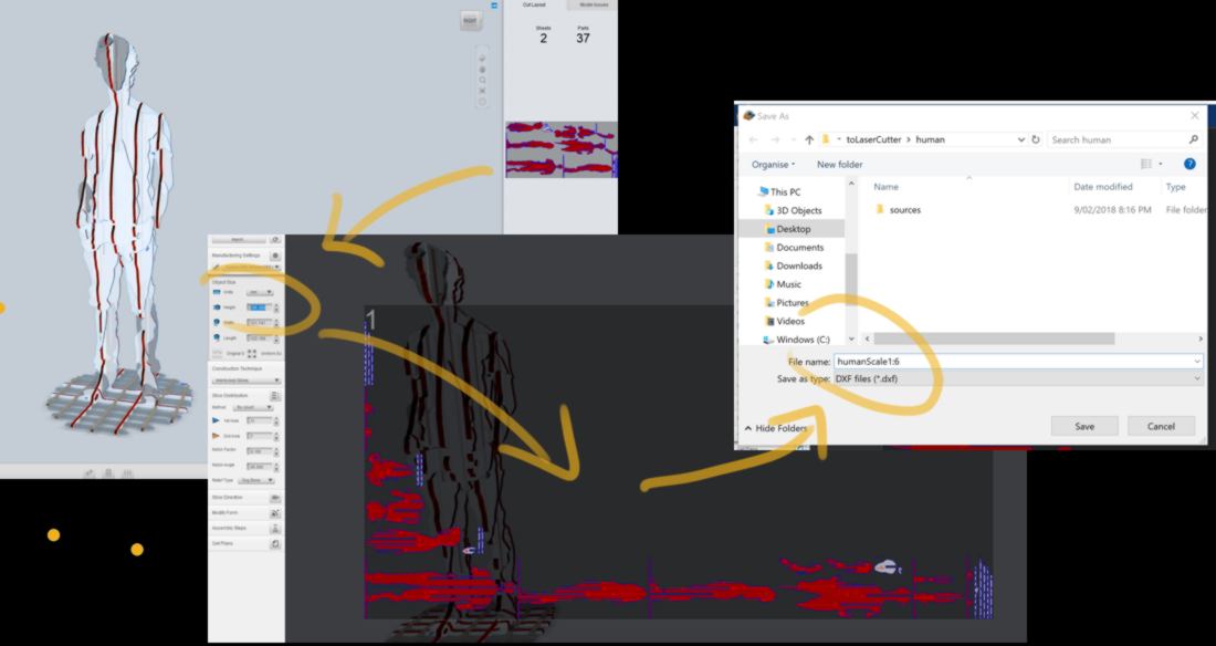
the path generated is intricate, and some parts are disconnected from their cores. Slicer also displays several warnings. I decide to have a closer look at the sheet in Inkscape. Interestingly the only format working correctly is .pdf. When getting closer to my model, I notice some issues : some parts are separated from the rest of the model, some other are barely held by any material.
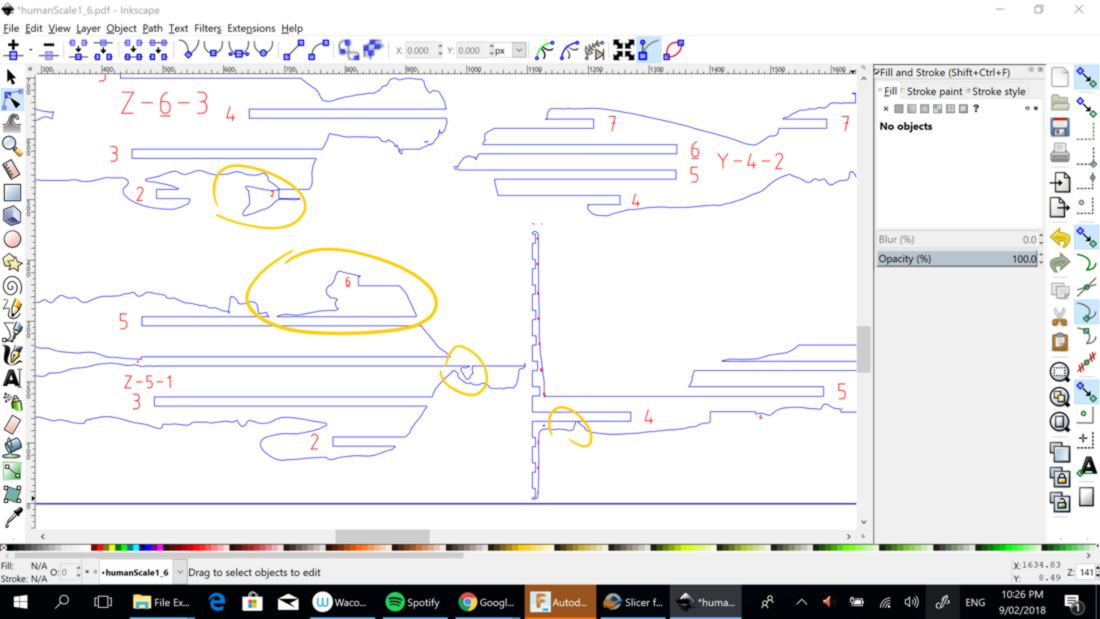
This model is likely to fall into pieces very quickly, and likely to look much less defined than what Slicer displays. Ideally, to make a cardboard version with very little material, my initial shape needs to be adapted to the slicing tool. This can be achieved by having shapes which aligns better with the slices according to the mode selected.
This model used here looks good, but will not be ideal for this particular fabrication process. I decide to save my cardboard for a better project.
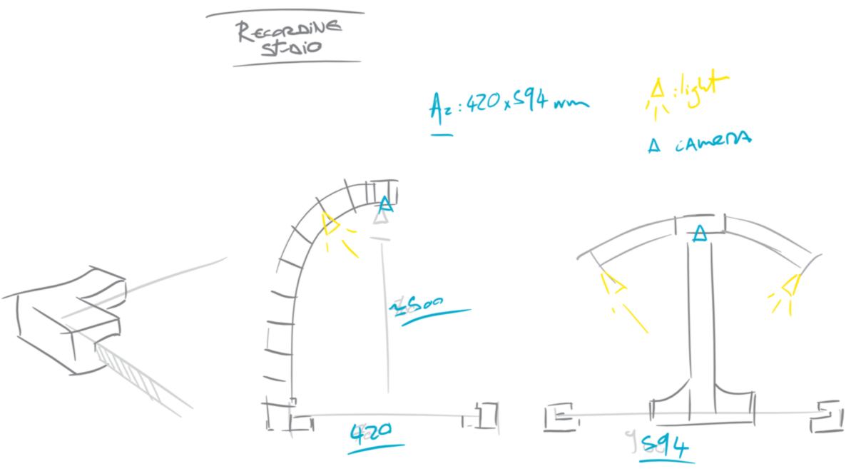
10.02.18 /As described in my final project I need a recording table. This could be done by using both plywood and cardboard, materials we are supposed to use during this week. I wish make an object that is practical, so for now, the design is very simple:
I familiarise myself with FreeCad as well as Blender and its add-on for parametric design, Svershok, using tutorials on the internet:
I do so to step away from Fusion 360, and begin to use of open-source softwares. My researches bring insights on the specificities of each softwares and their individual strengths. Learning from that, I decide to use FreeCAD and Slicer to design the recording table, leaving Svershok for other designs later on.
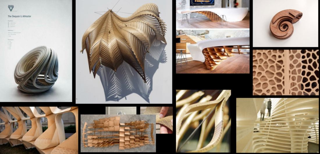
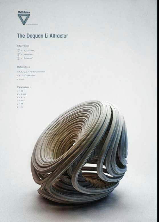
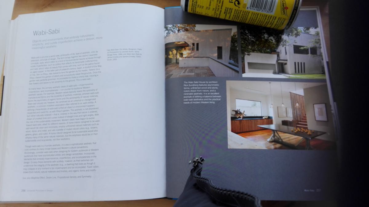
11.02.18 /I am heading to the museum of design this afternoon, to get some fresh air. It is the first time I see a mop and a bucket in a museum. There are also more inspiring designs:
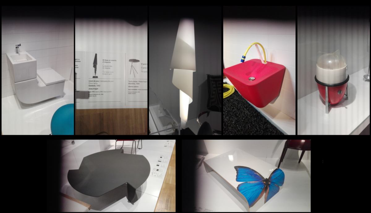
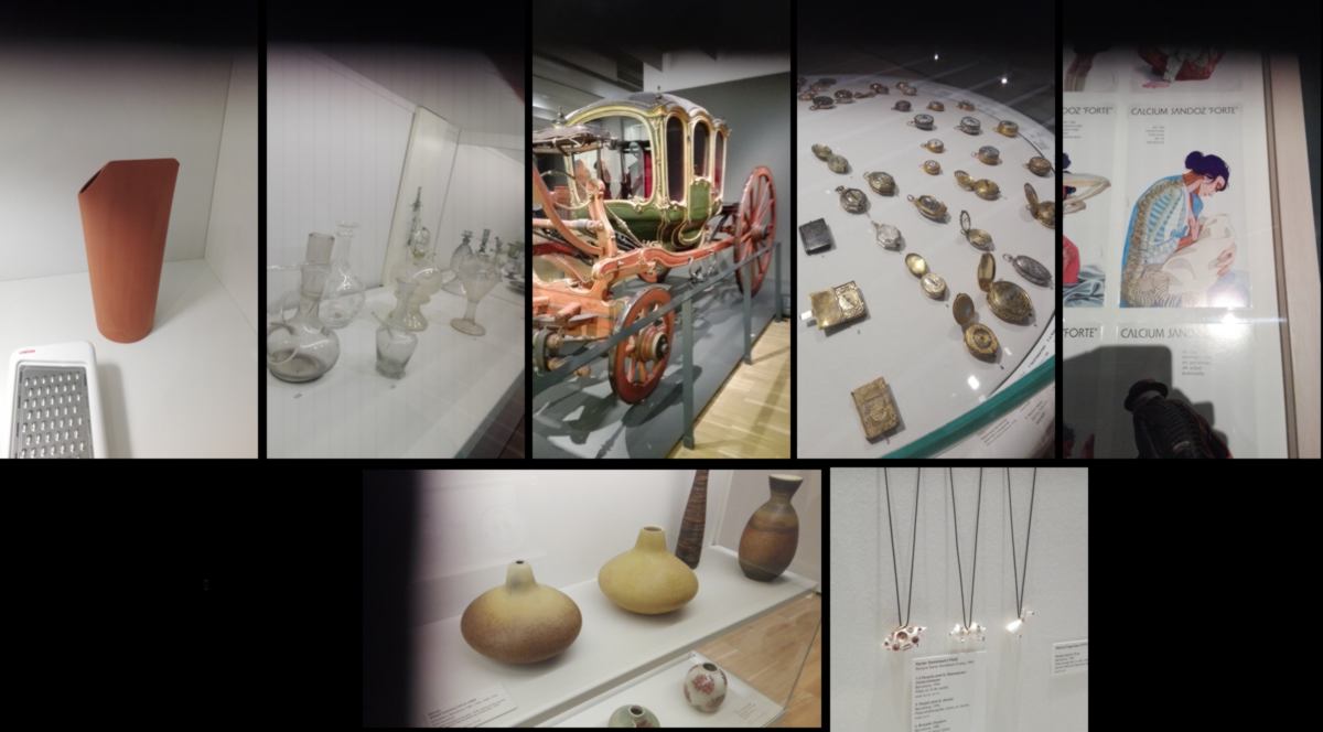
New Zealand is a cultural desert, so I take in everything I can in while in Europe. I finish my reading about design. This book offered a broad approach of the subject. I have my favorites, like this description of a specific philosophy behind design, consisting in adding a small, random imperfection to make any design more natural and human:
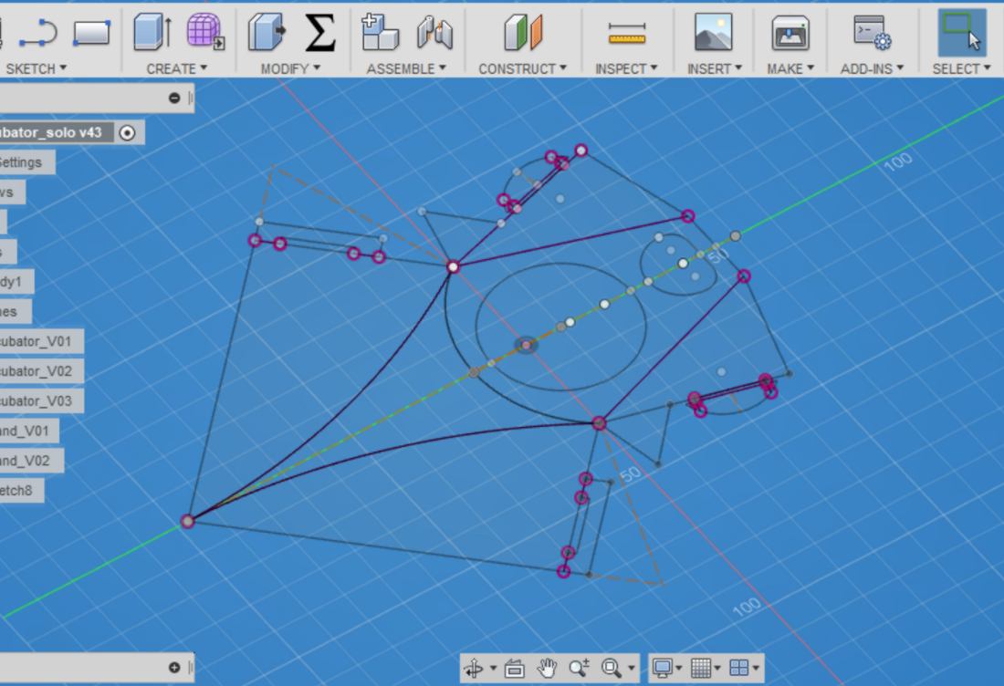
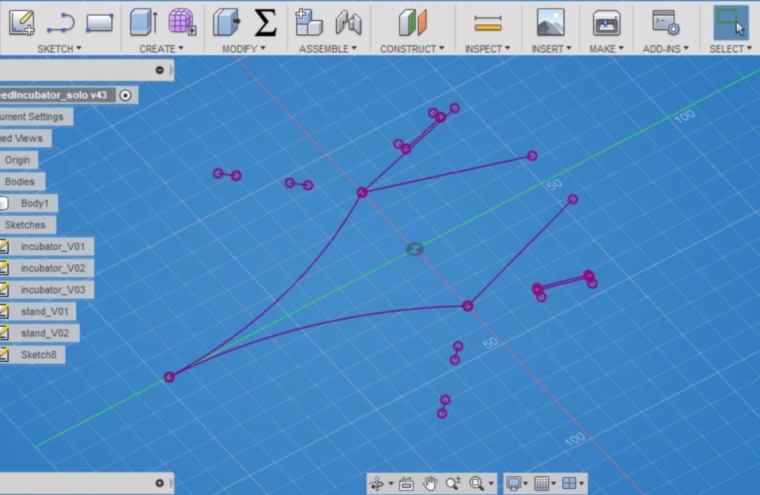
I must express my utter disgust for FreeCAD's - overhangingly - steep learning curve. I guess that the difficulty does not come from the software itself but the lack of a proper set of introductory video tutorials. I have collected videos, all extremely precise, however each of them describing a different workbench of FreeCAD - and nothing seems connected.
I bump into many potholes, struggling with the most obvious features. Out of my experience, I still get to understand better the CAD design process:
I end up with much cleaner sketches on all softwares.
The format of the Fab Academy requires me to keep a hasty pace to deliver on time, and it becomes clear that with this purpose in mind, I will consistantly use Rhino and Fusion360 (Rhino is compulsory to laser cut at FabLabBcn, and Fusion360 is very intuitive). Despite all the help I can find in Fab Lab Barcelona, I must put my goal of only using open-source softwares aside for now.
12.02.18 / I begin this new week by getting used to the laser cutter, how to switch on the fuses, ventilation and go through other safety checks, as well as calibrating the z-axis manually.
I work my way through the workflow required:
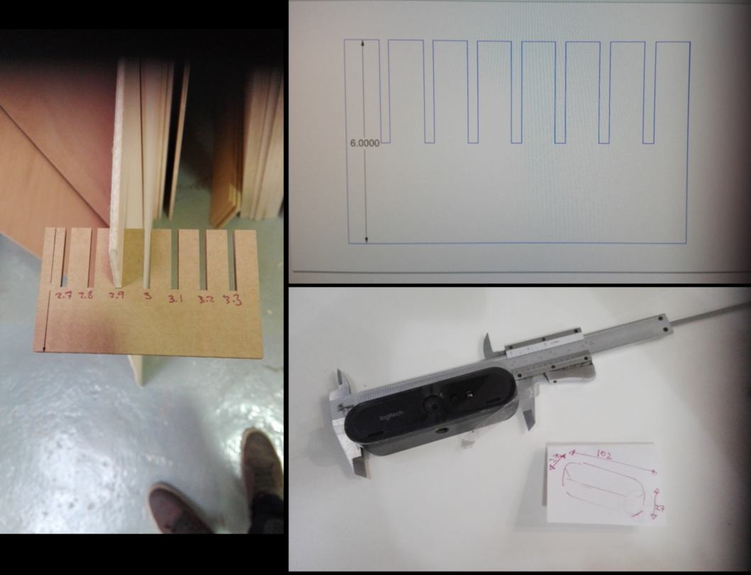
Although I do not have the kerf calculated yet, I do have the press-fit test from Friday, which enables me to start designing the next object. In order to record video tutorials, I need a recording table :
This design is made out of two materials : cardboard and plywood. I need to take some preliminary measurements before getting started. I make another press-fit test to calculate the ideal width of the slot required for the plywood. I also need to measure the webcam, which flew with me from New Zealand:
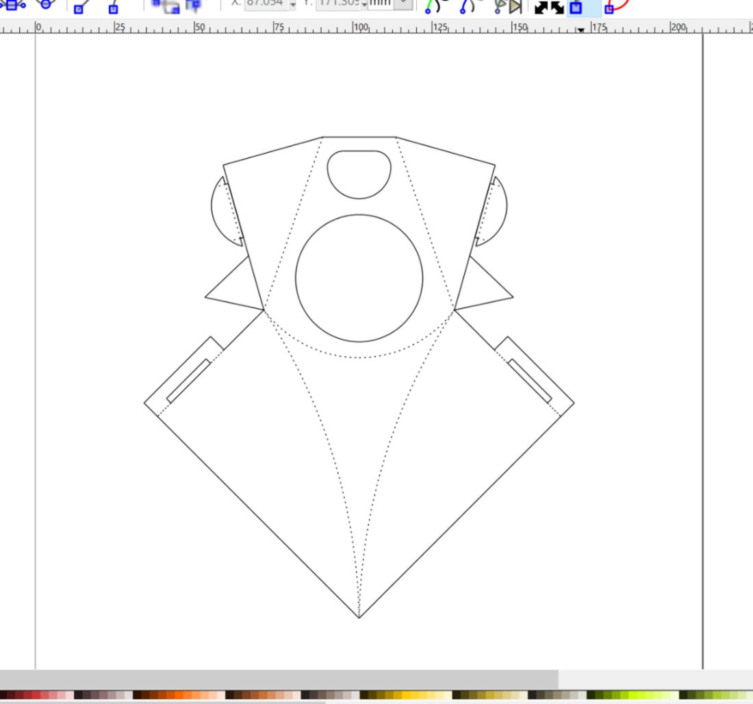
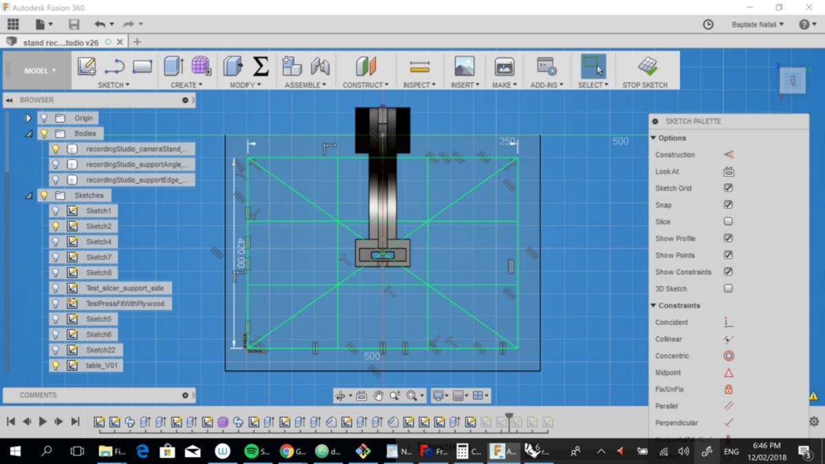
I aim at using Slicer to build upon what I did last time. This time however, I ensure I make a bulky, simple volume. I pay extra attention to design something which will keep the expensible 4K webcam out of trouble. All slots designed for the plywood are parametric, In the eventuality of a last-minute change of mind/ material.
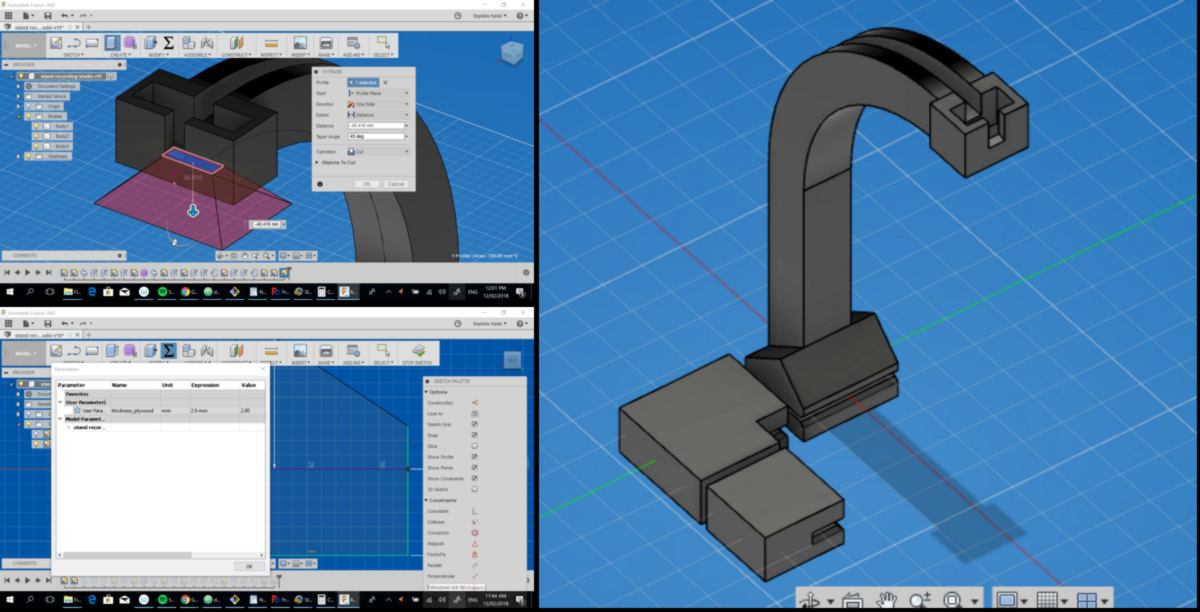
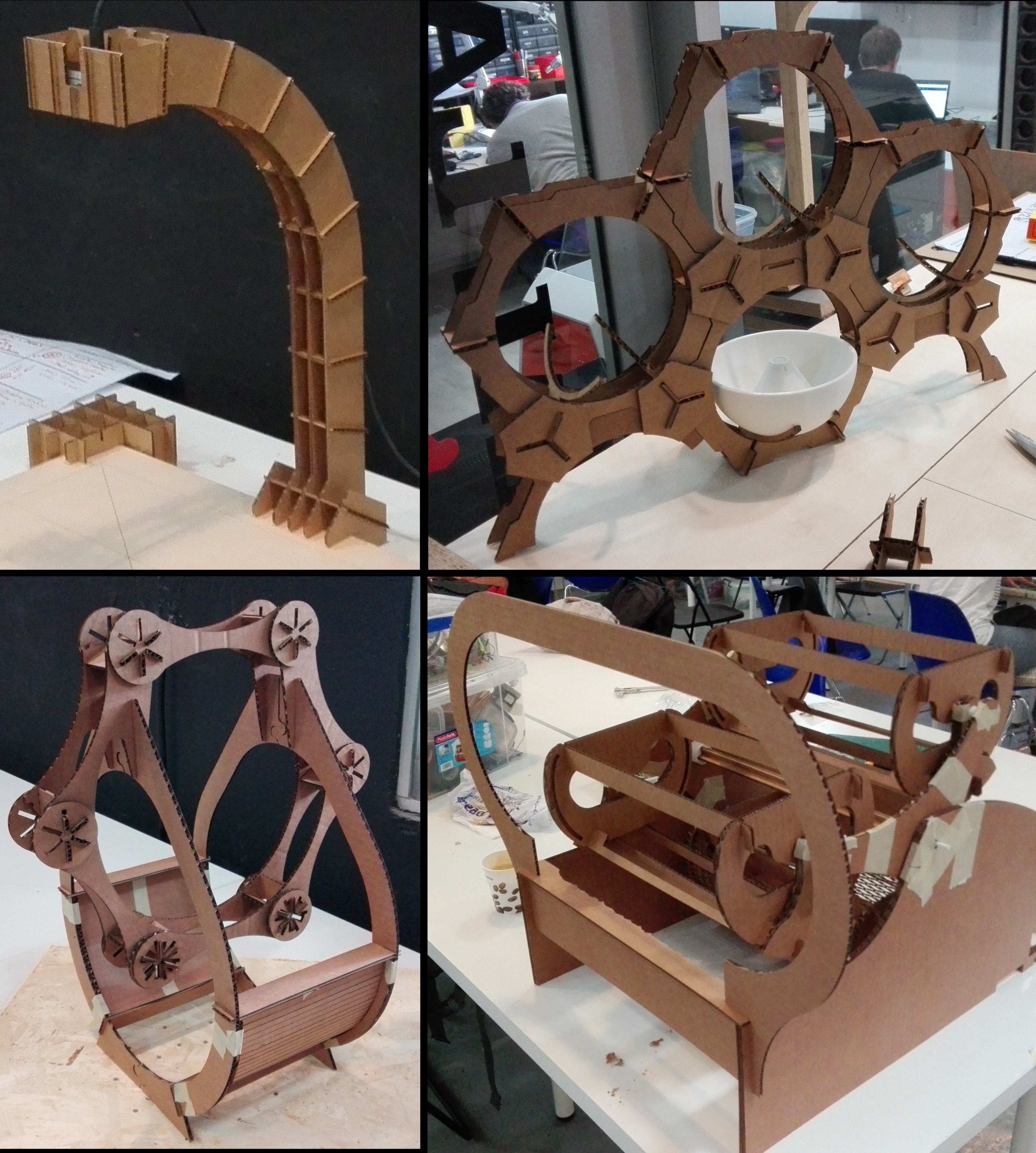
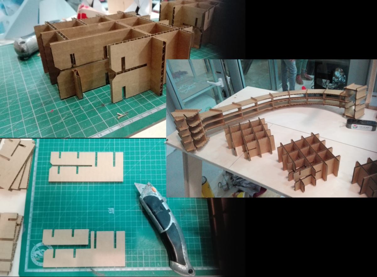
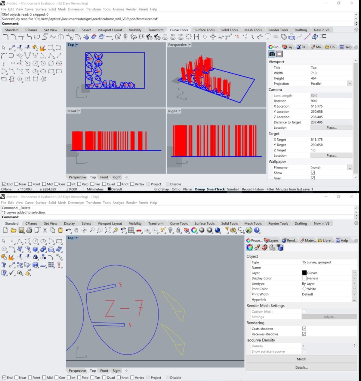
I throw each part in Slicer, starting with the camera stand. Since the camera is L-shaped, I modify the construction mode, using a circular pattern to align the cross-section. I then add a large number of slices to ensure I have slices in locations critical for the sturdiness of the model. I then edit the model manually to reduce the number of slices and save on material used.
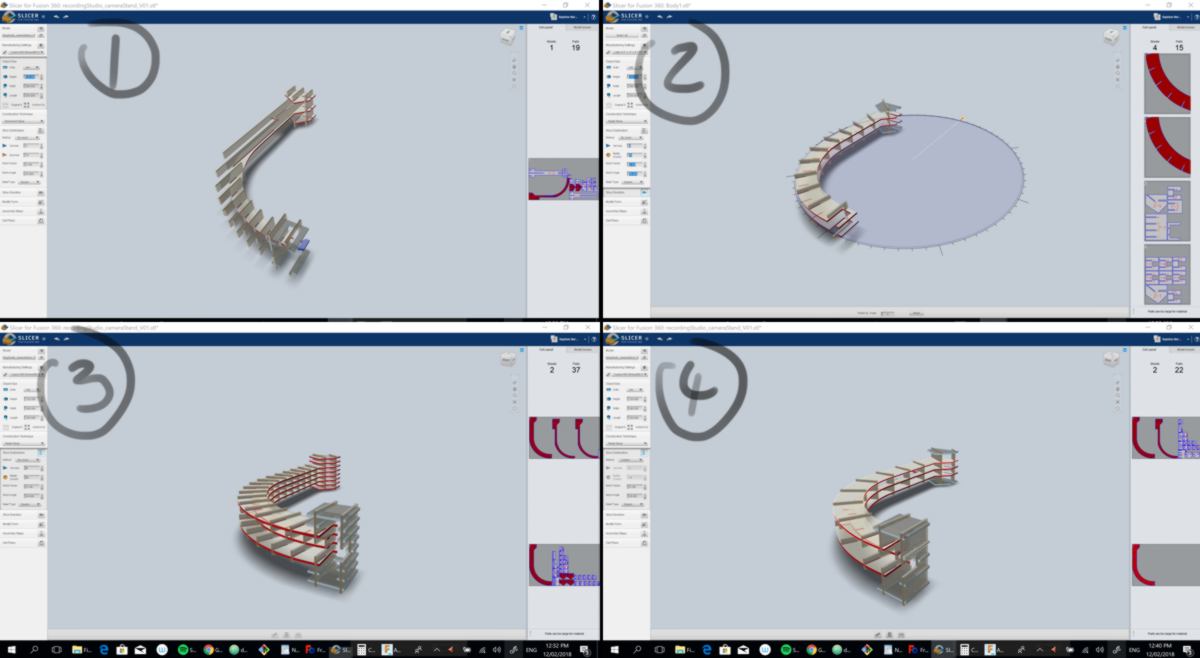
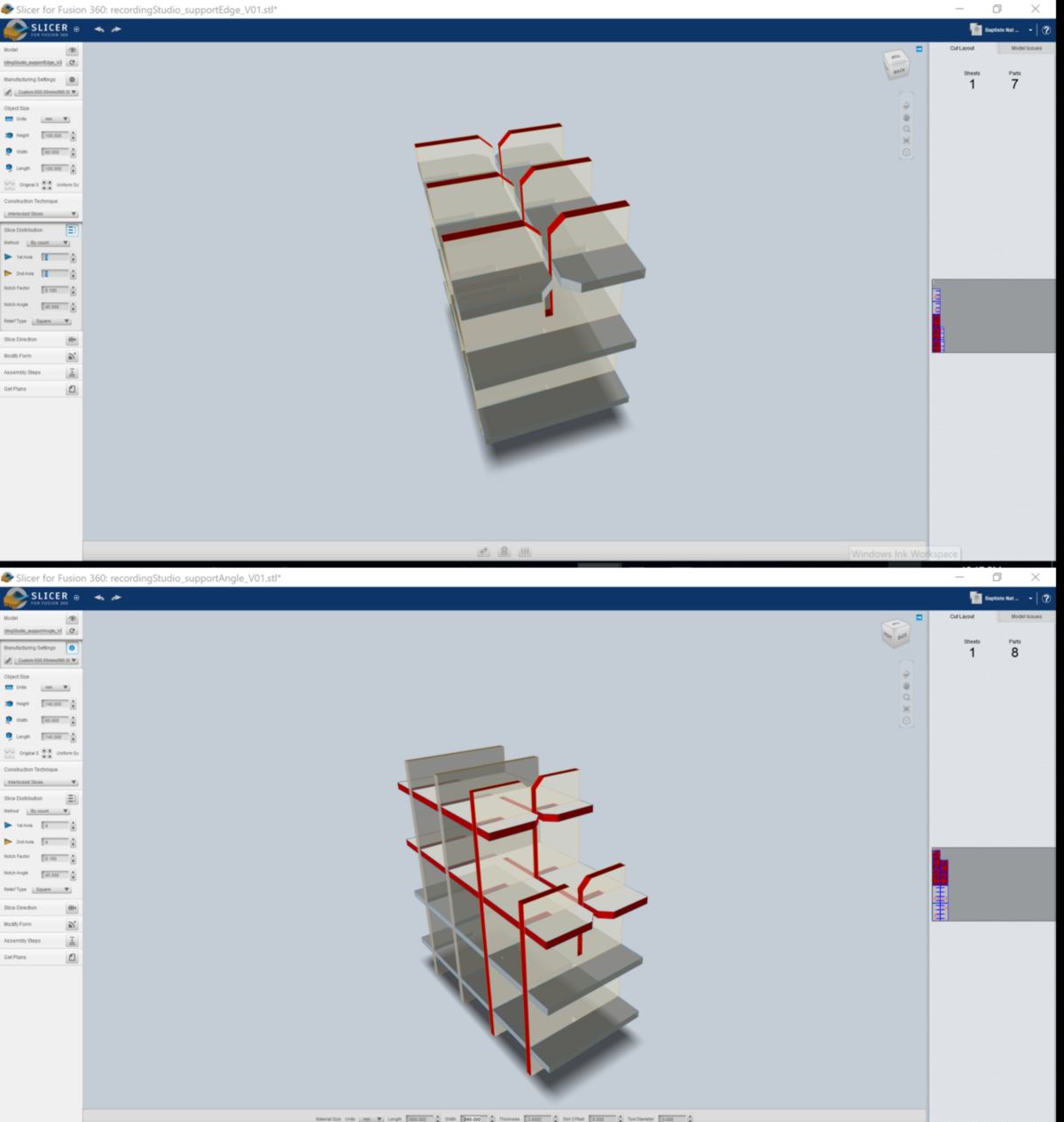
Other supporting pieces are sliced as well:
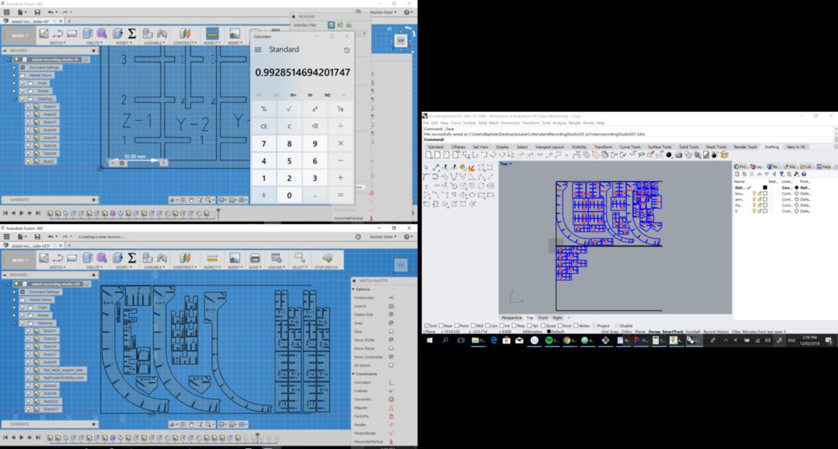
I import my models back into Fusion to nest all pieces together on a single sheet fitting in the laser cutter. Fusion has trouble importing at the right scale, so a manual adjustment is required. Fusion also has a hard time dealing with the many points of the model. I decide to process the design in Rhino, which handles them without difficulty.
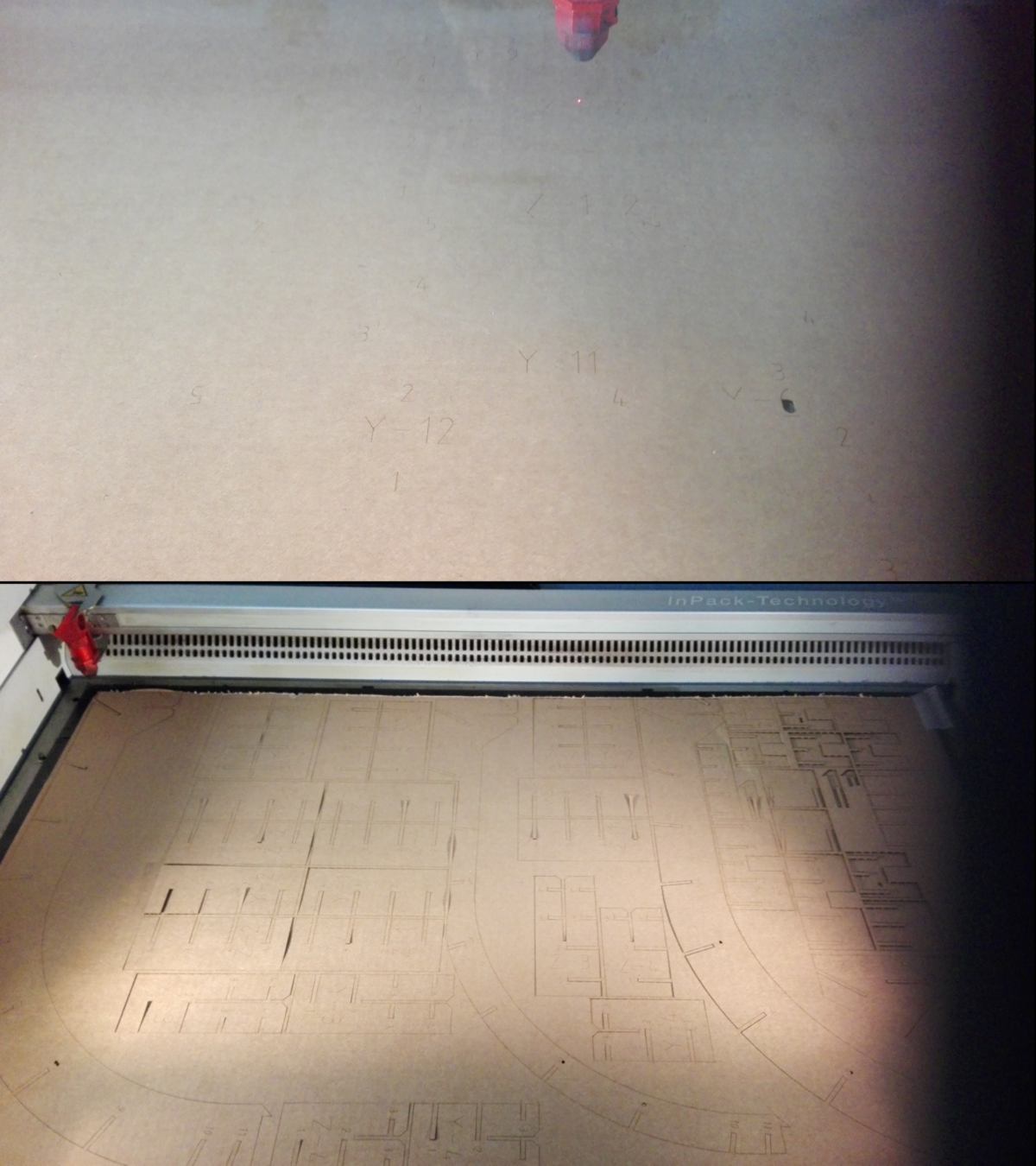
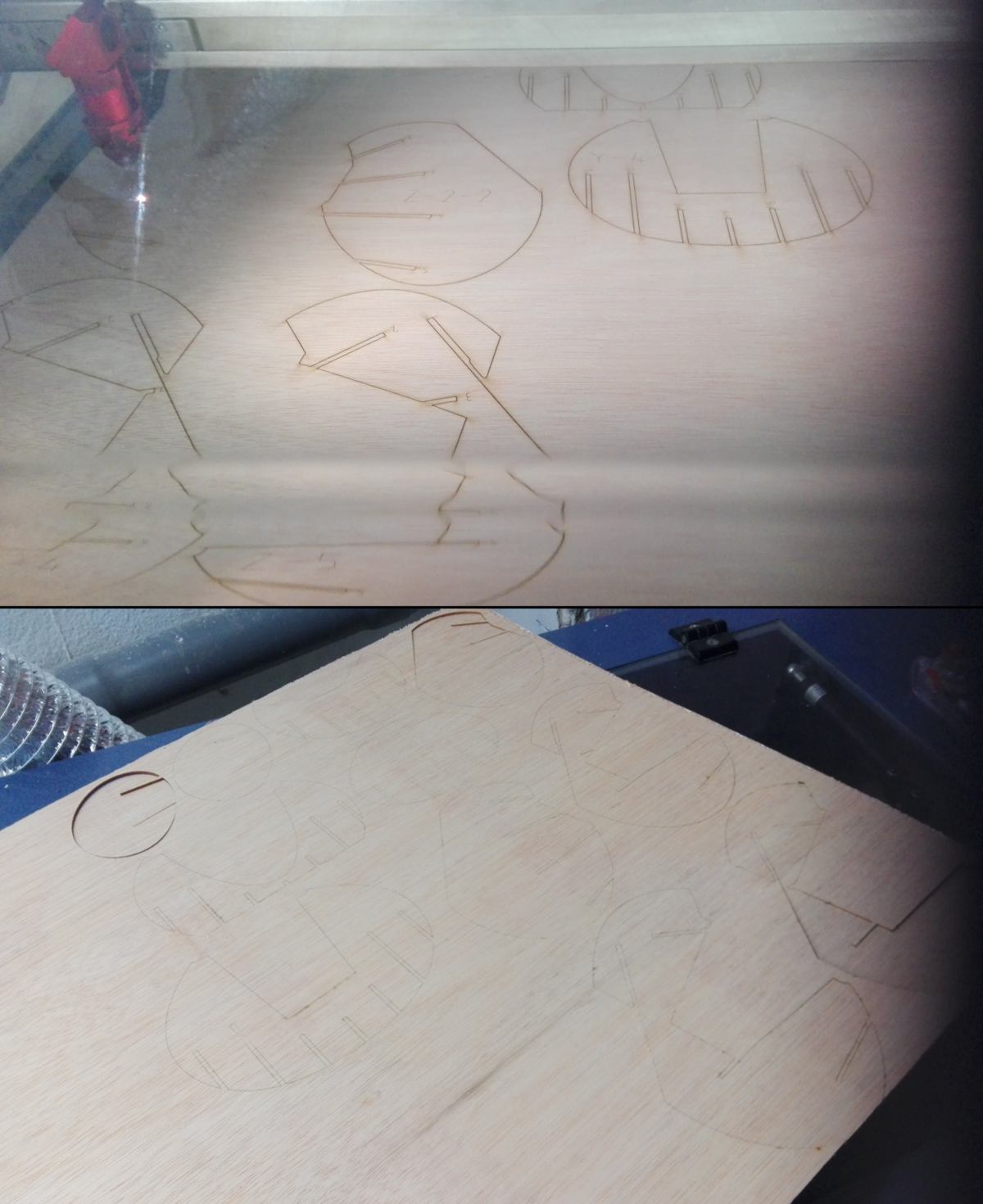
The design is loaded in the Trotec 400 and the cutting begins. I adjust the settings for the written references and the outlines. All numbers are etched on the cardboard, then the pieces are cut.
I put all the pieces together. Slicer has designed the model in a way which makes it impossible for some slices to fit in. I manually cut what gets in the way without compromising the functionality of the model.
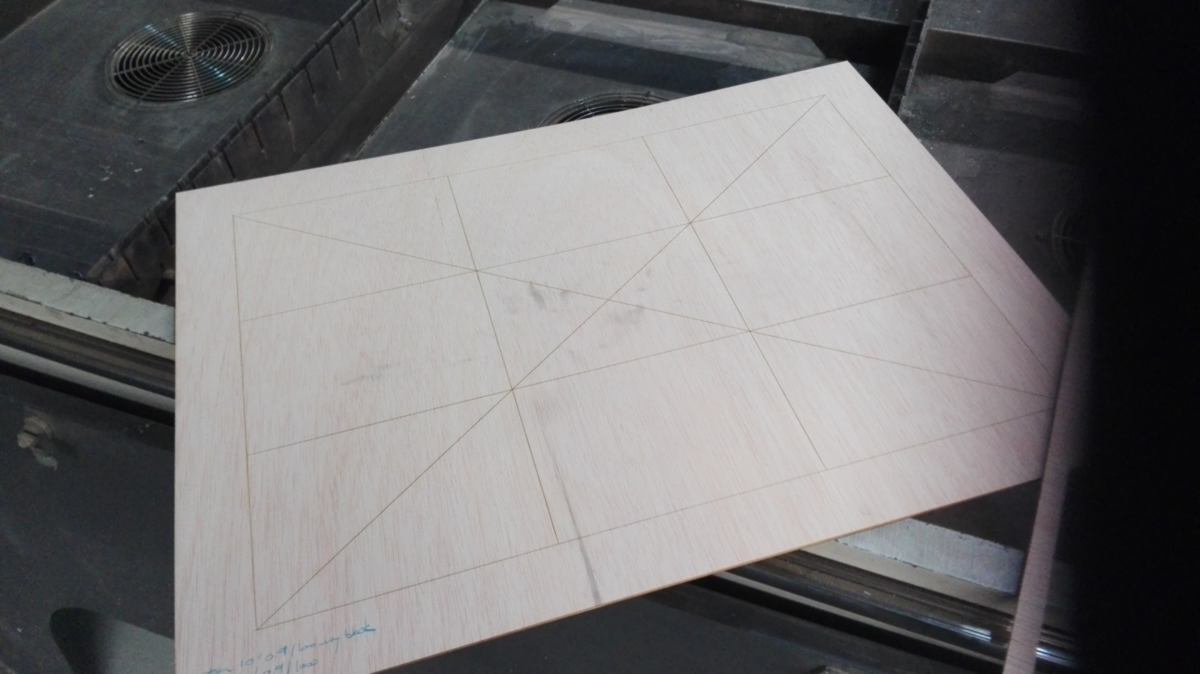
Then, I design the etching and cut of the recording table, designing a layout which will help me test the camera and respect the rule of third. I adjust the settings of the laser cutter using another student's test as a reference.
I assemble everything together. The camera is locked into place, the fit for the recording table is snug. The cable of the camera follows the groove designed for it.
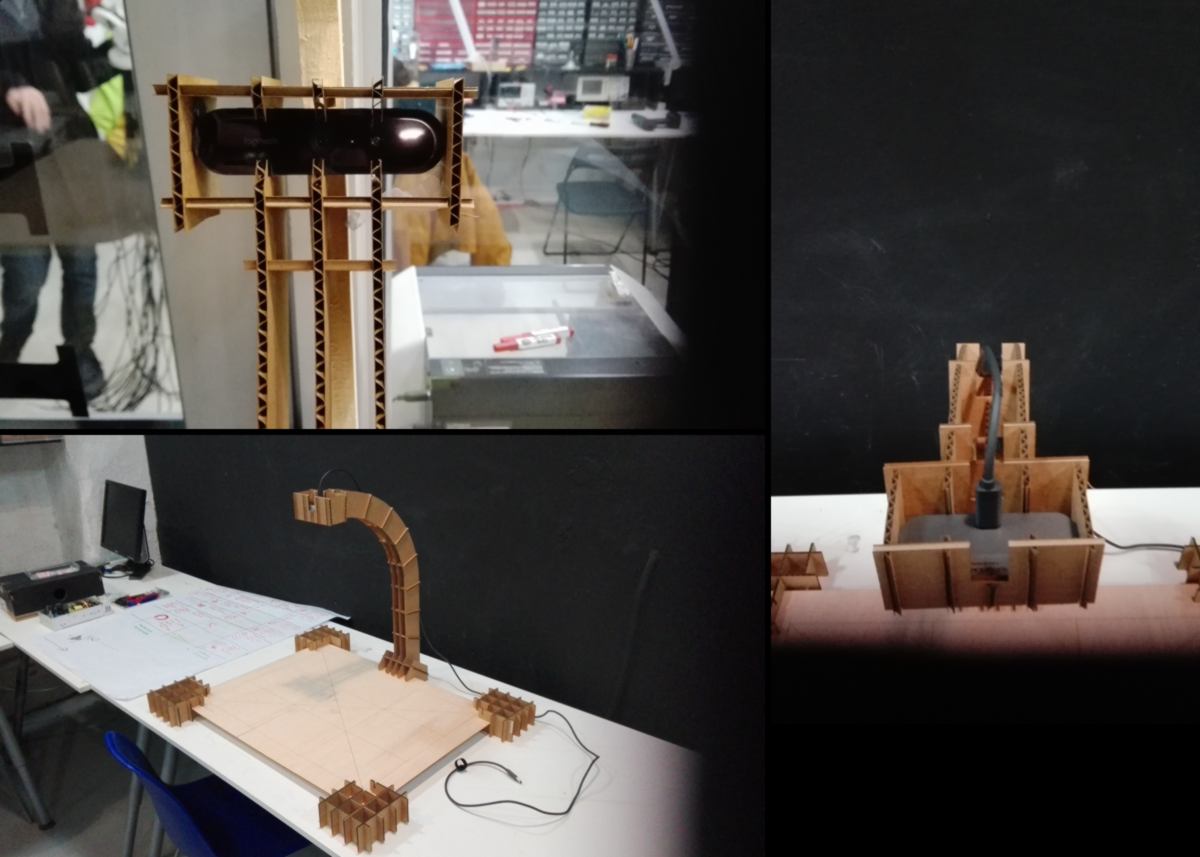
This prototype brings about some valuable insights. Since the camera is connected to the recording table, it follows its every single shakes. Therefore, I must adjust it by separating the camera stand from the rest of the recording table. Ideally the camera should be grounded so as not to move, but it still needs to be aligned with other elements.
Also, the shadow of the camera stand shows on the recording table. As expected, a set of lights located on each side of the camera stand is required. Finally, A more sturdy table and padded feet will make the recording more steady, especially in case a material must be cut or hit during the tutorial.
13.02.18 / "Our passage through life consists of an effort to get the maps in our heads to conform to the ground on which we walk" G.L. I find this quote sent to me so relevant for what we are doing at the moment.
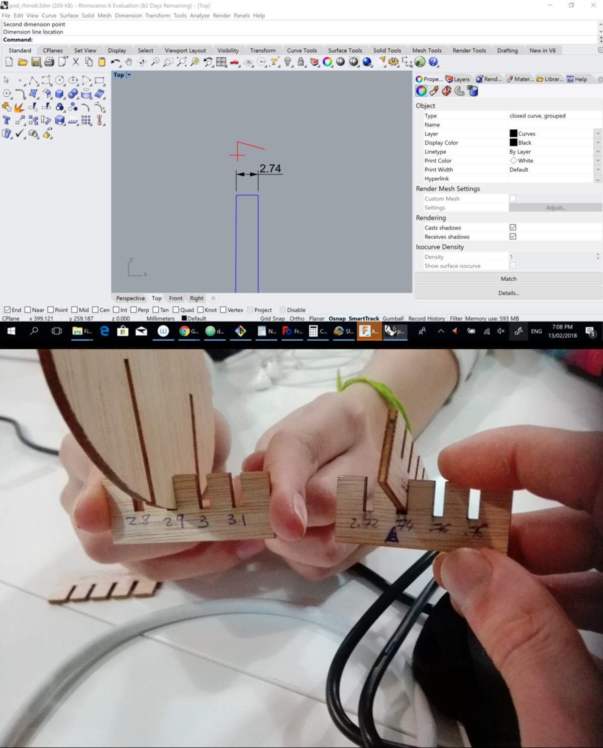
After cardboard, I will begin working with wood, a less forgiving material. Getting the width of the cut right is crucial, therefore I make a press-fit test. I am going to do a first test using a scale on the tenth of millimeter, then using a scale in the hundredth of millimeter. I aim at getting a snug fit.
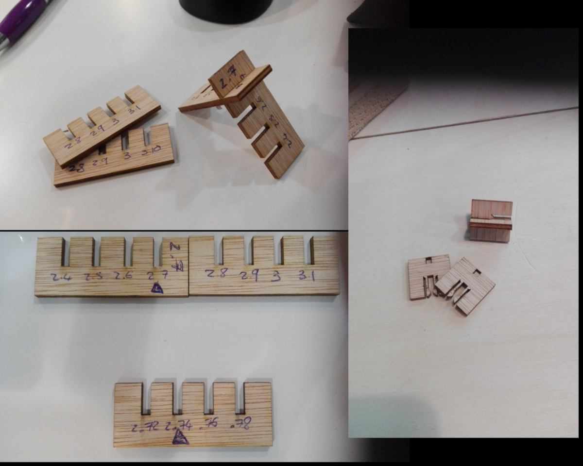
I am willing to explore more shapes to clip two pieces of plywood together but the laser cutter is taken by assault. I ask a user to cut me a 10mm per 10mm square of plywood. I am going to use this to measure the kerf of one of the laser cutter. I have seen complex, advanced techniques to do so, and I still don't grasp why they have developed such complex techniques for a simple measurement. I am substracting the width entered in the software by the measured width.
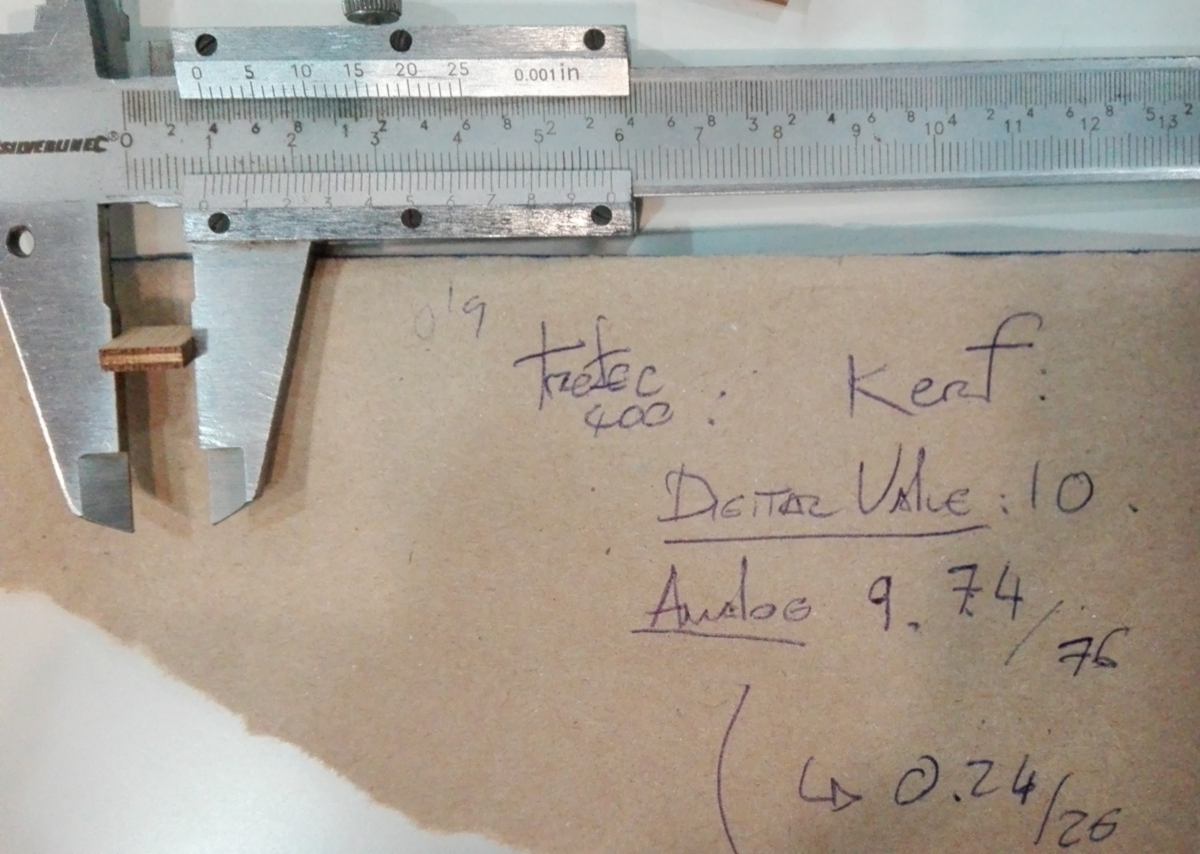
What I use is an analog caliper, I can only guess that the value of the kerf is between 0.24/2mm and 0.26/2mm. So 0.12mm roughly.
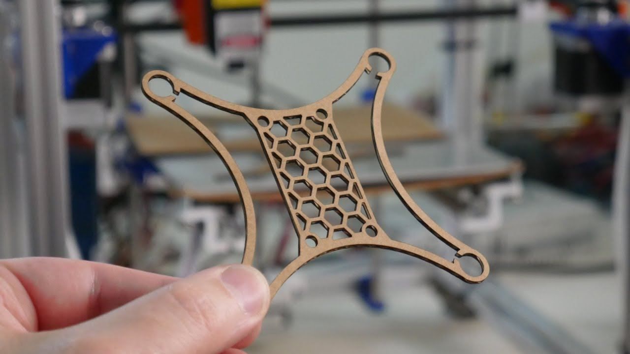
I carry on designing a parametric object. Last week I started potting around with the idea of a green wall, and I want to expand on that. Rather than sketching, I change my approach and directly design it in Fusion. Apart from plywood, I need to 3d print a waterproof pot which will fit in the stand. I reuse my siphon system from the previous week.
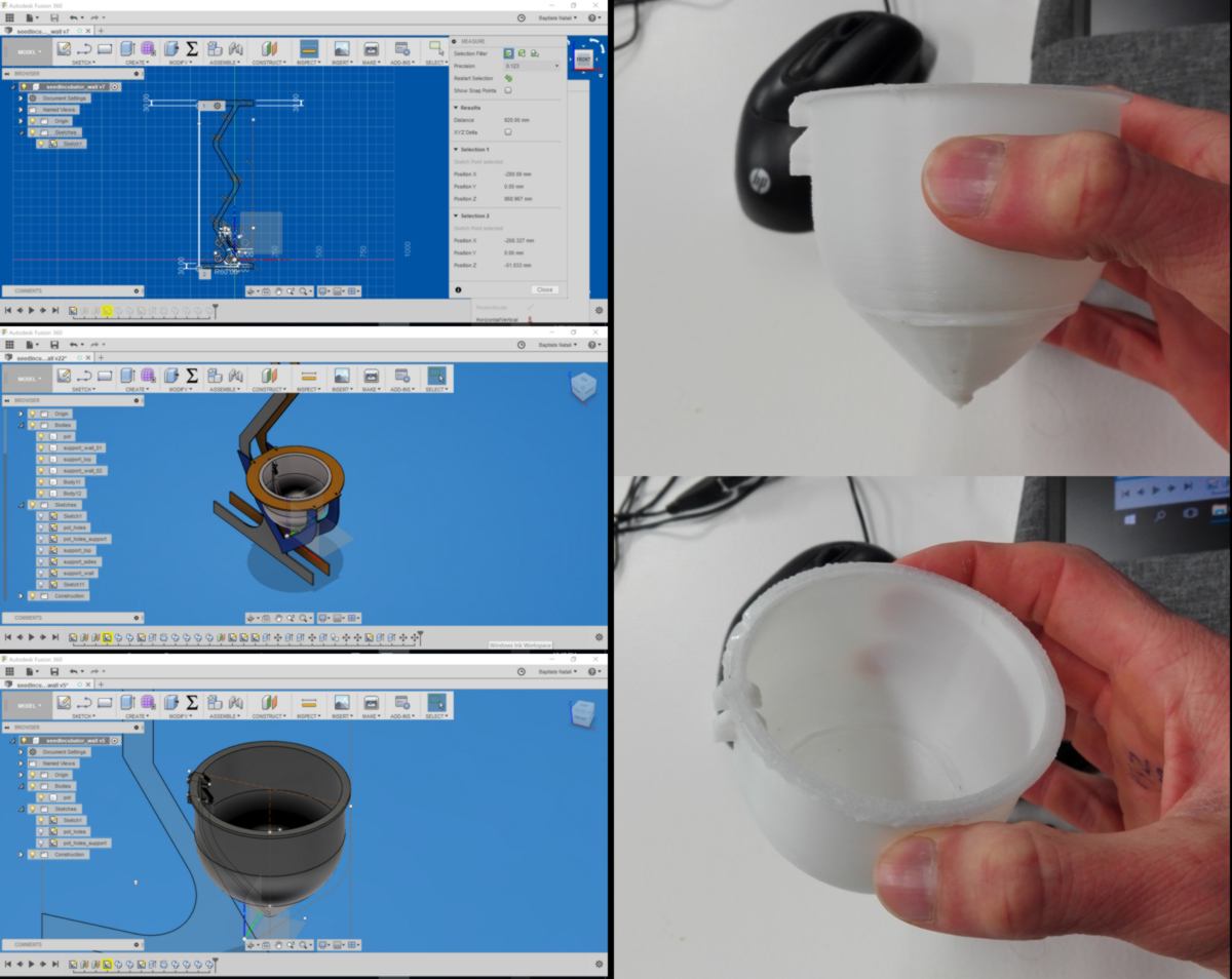
I end up having issues. To speed up the 3D printing process, I set up the thickness of each layer to 0.4. The nozzle is 0.6 wide, so I should technically get away with it, but the printer partly misprints the model. I won't be able to use it as a waterproof container, but I can still use it for visual reference.
I also get lost in technical details in Fusion. I make things more complicated than they should be. Sketching really takes the technicality out of the designing step, so I revert back to it :
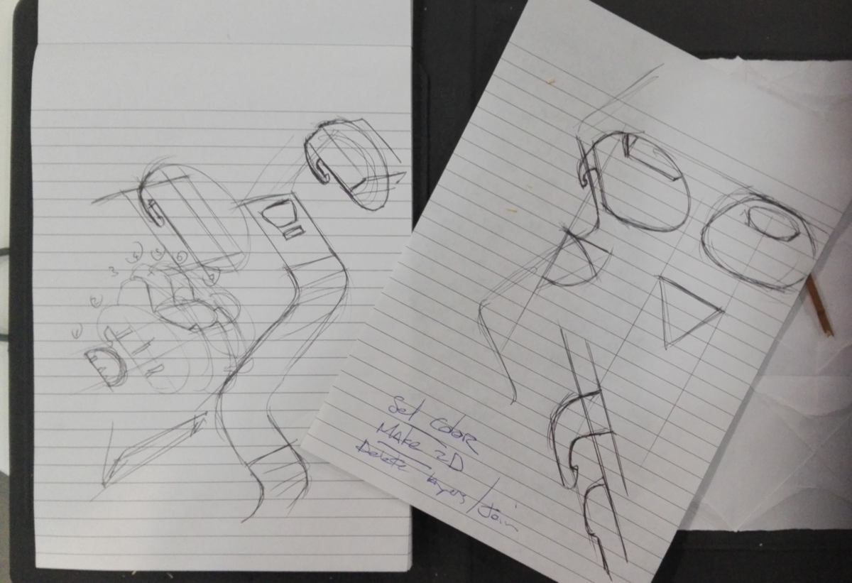
I see now that what I want is a more organic shape, so I sculpt it using the mesh tool in Fusion. It shares similarities with the edit mesh mode of 3dsmax, so I quickly grasp how to use the basic tools. Again Fusion360 proves to be user-friendly. I use Slicer again to prepare the model before cutting. This time I test another type of construction, where the slices are drawn perpendicular to a curve that can be edited. this construction type adapts well to this bean-shaped object.
The reason I use slicer so much is that the final object provides a sense of volume using very little material. The workflow is laborious but faster than 3d printing and less energy-intensive.
The workflow between Slicer and Rhino is not flawless. The design exported from Slicer appears as a 3d volume in Rhino. I go through the following steps (provided by Anastasia) to correct this issue:
Once done, I get rid of small pieces who are not critical to provide me with a sense of volume.
I bring a fresh piece of wood from the storage and send the file to the laser cutter, using the same power/speed/frequency settings as before. Surprisingly, the cut does not go fully though the sheet. I ponder whether a whole day of intense cutting might have affected the machine.
A bit of a shake and push gets the pieces out, ready for assembling. When it comes to putting the slices together, it does not fit in. I checked the value I entered for the width of the cut and it is correct. I measure and compare the material used with the press-fit scale created earlier, and come to realise that the plywood used is 0.16mm thicker that the one I ran my tests on. That explains why the laser did not fully cut through it previously.
I learn today that I have to test my settings for each new material used for cutting, Although it is useful to have reference sheets, no two pieces are the same.
I am glad to learn that on small, inexpensive material. However all students together have generated a large amount of waste. It would make sense to be able to recycle the cardboard on-site.
Reflecting on what I did this week, I wish I had time to fully develop a working prototype for the green wall, as a parametric design. The many mistakes I have made are helping me reshape the design, and I have a clearer idea of what I wish to achieve, which is actually much simpler than I initially envisionned.
I know now that the kerf of the laser cutter sits between 0.124mm and 0.126mm, which means that to obtain a tight press-fit slot, I must substract 0.25mm out of the total width of the slot. Example : for a 4mm thick plywood, I must cut a 3.75mm slot.
I also know that to find the right cutting parameters for a material, I should start with low power / high speed and increase power or decrease speed until I get the expected result. Not the other way around, unless I am organising a barbecue.
I also get reminded that:
As an introduction for the coming week, I receive a piece of electronic from Hong Kong:
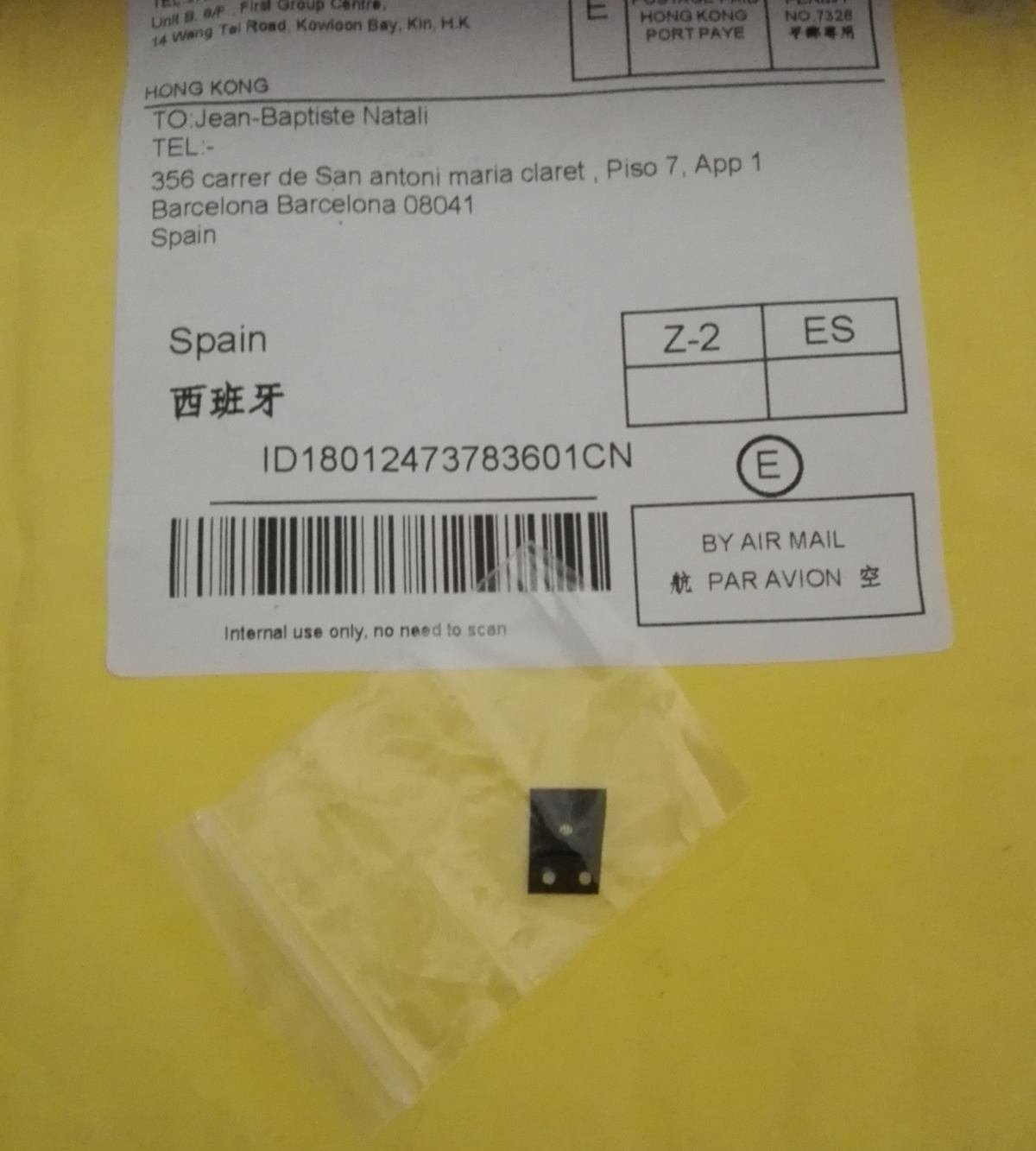
This is a replacement for the wifi/bluetooth chip that blew on my cheap Huawei, and I must fix it myself. It is a good timing to dive into electronics.