Attending the Fab Academy in Barcelona, I document each week of intense learning as I come across new digital fabrication techniques.
This documentation is as much a report of what I do as a reflection on why I do so, and will hopefully guide me back to Oceania to spread and make good use of the knowledge gathered along the path.
--- summary of the assignment ---
objective :
Make something big (on a CNC machine).
what I did :
I designed a wooden structure for a waste minimisation system (potential to hold wormfarm, fishtank and plant). Design files are parametric. The design itself is modular. I paid extra attention to design for efficient nesting.
download :
Learning outcomes :
12.03.18 /This week we are thinking big. Using the CNC machine, we have been asked to make a LARGE object. It is exciting. This week though, the technique is not that new : I have already made a few big things with a CNC machine :

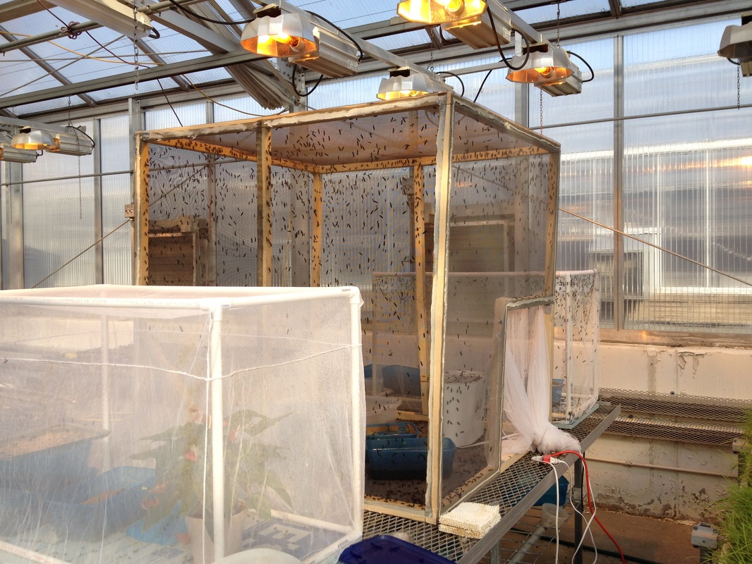
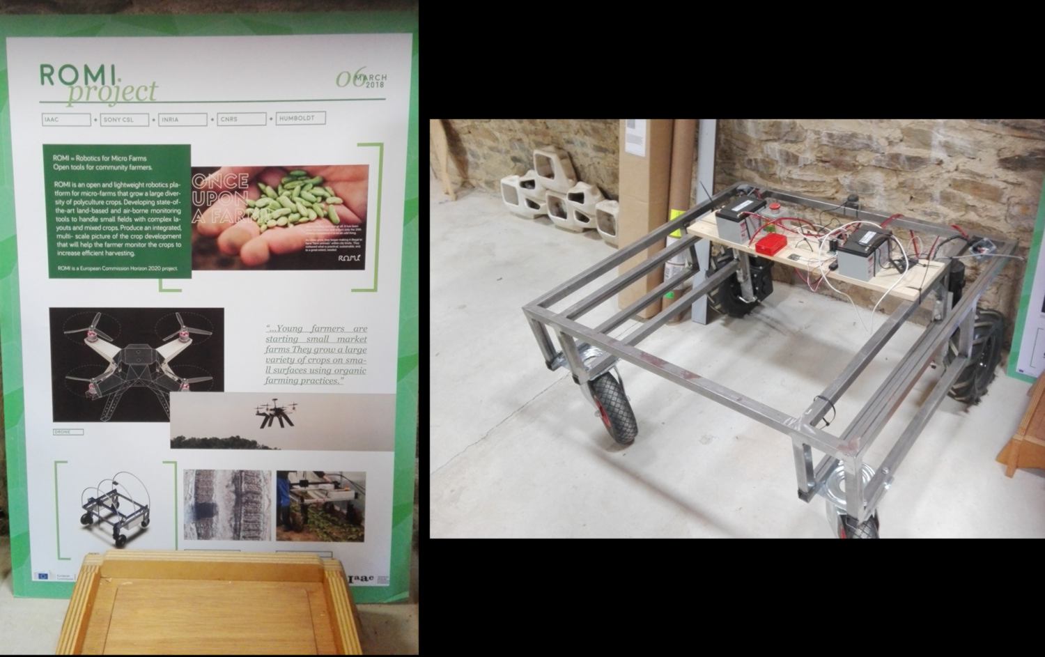
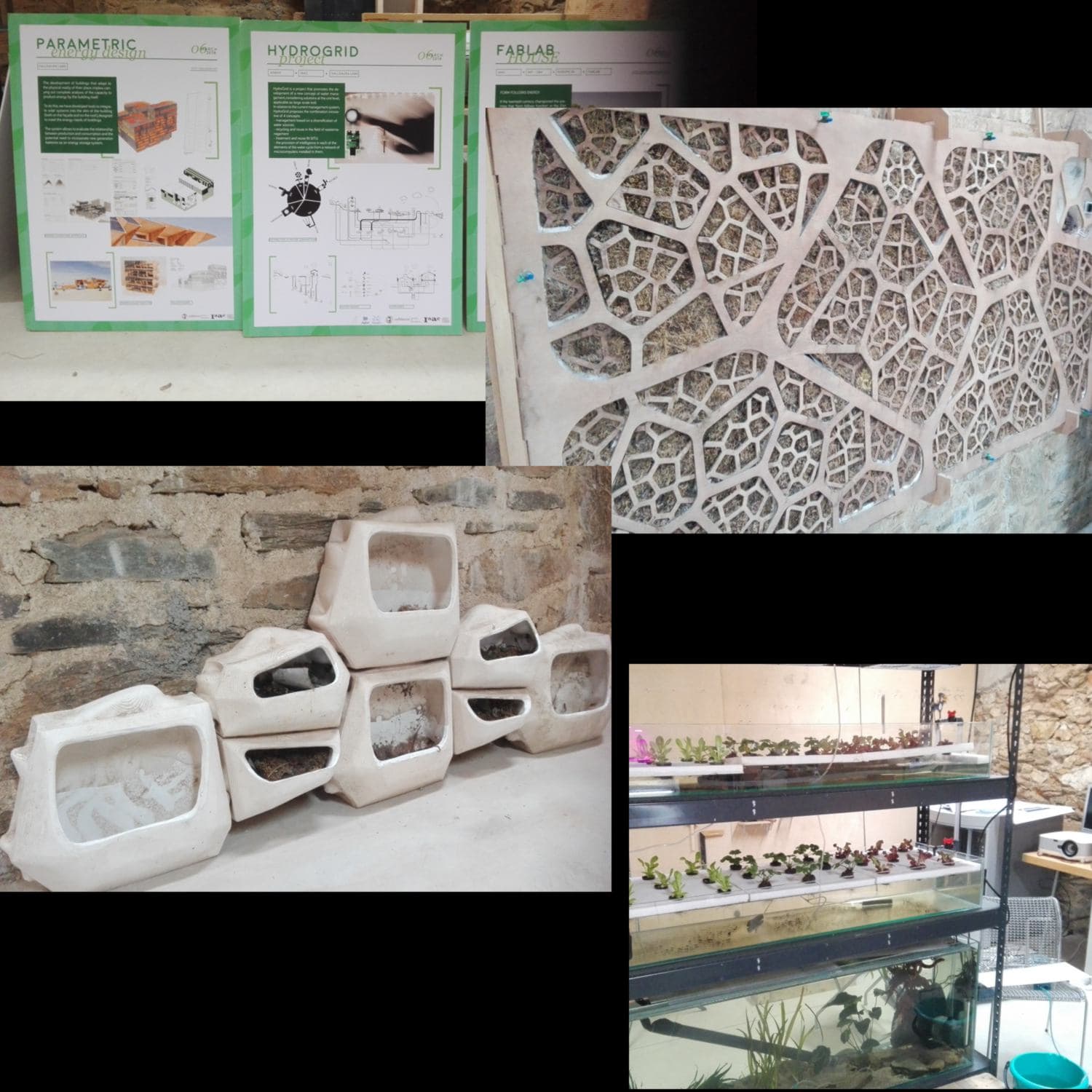
I am happy to take onbaord a challenge, something a little more complex. I will design the green wall I have been working on. Part of the green wall hosts a worm farm. The worms used are black soldier fly larvae (BSFL), well known to feed themselves on practically anything, multiply fast, and have the tendency to crawl away from their food source when mature. This is ideal in order to feed the fish : the worms will crawl out of their boxes and dive into the fish tank by themselves. Cruel world. Linked here are one video and another video explaining how it is used at a small, then large scale :
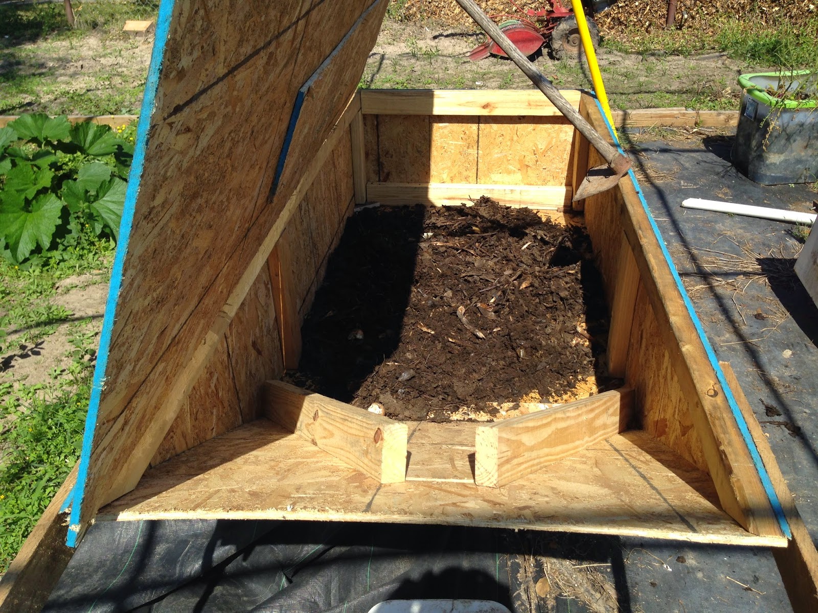
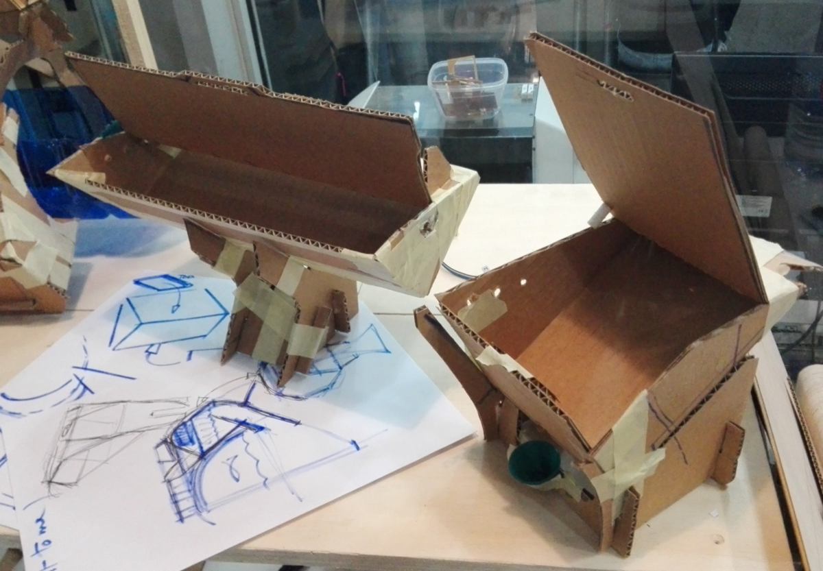
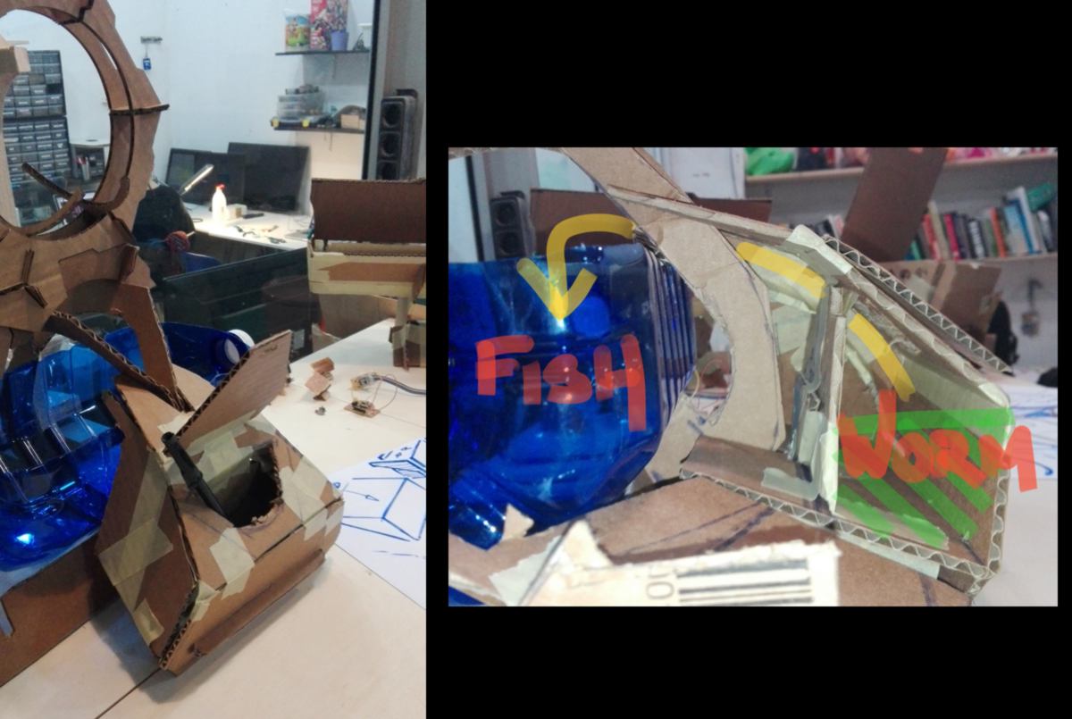
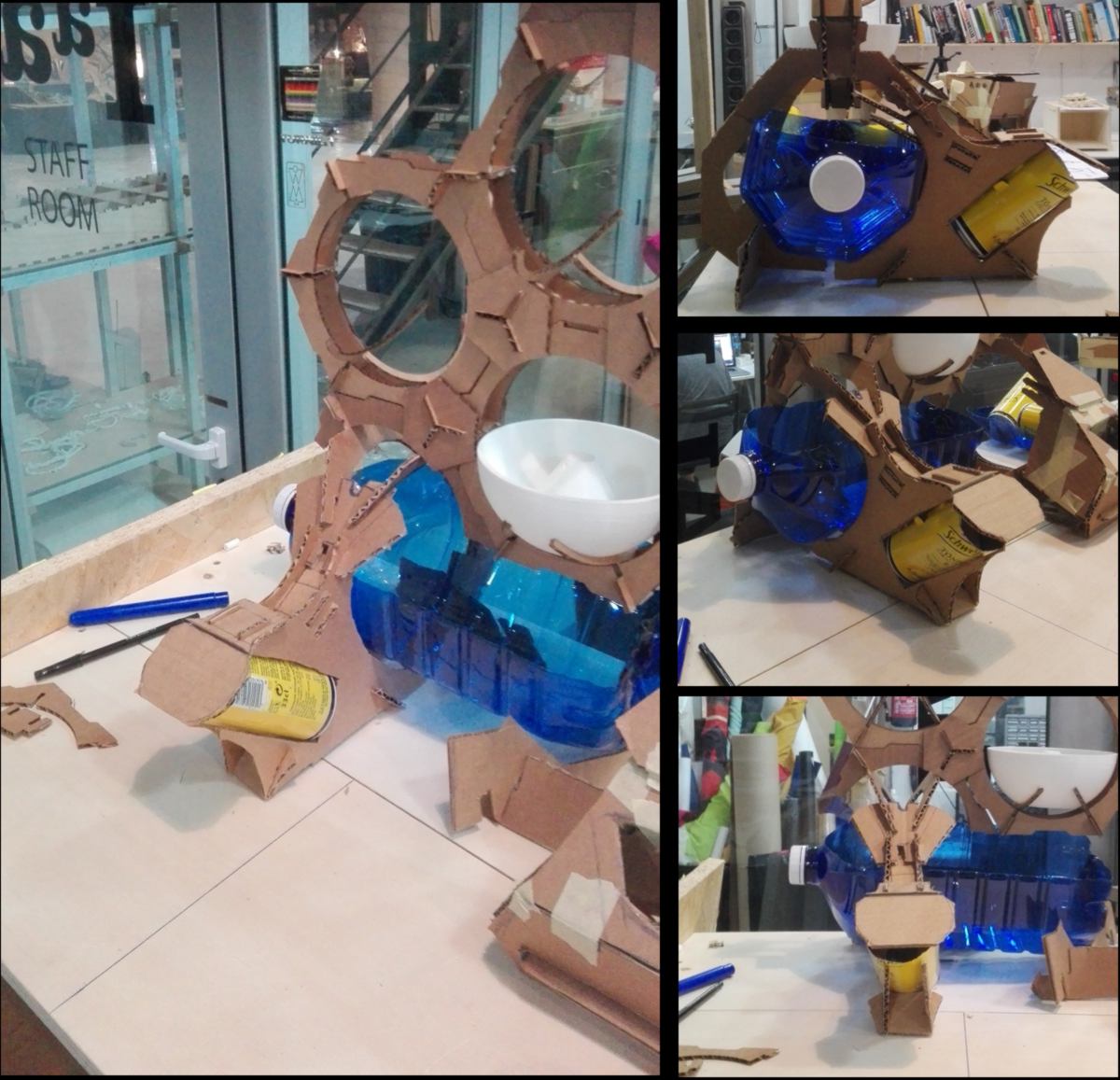
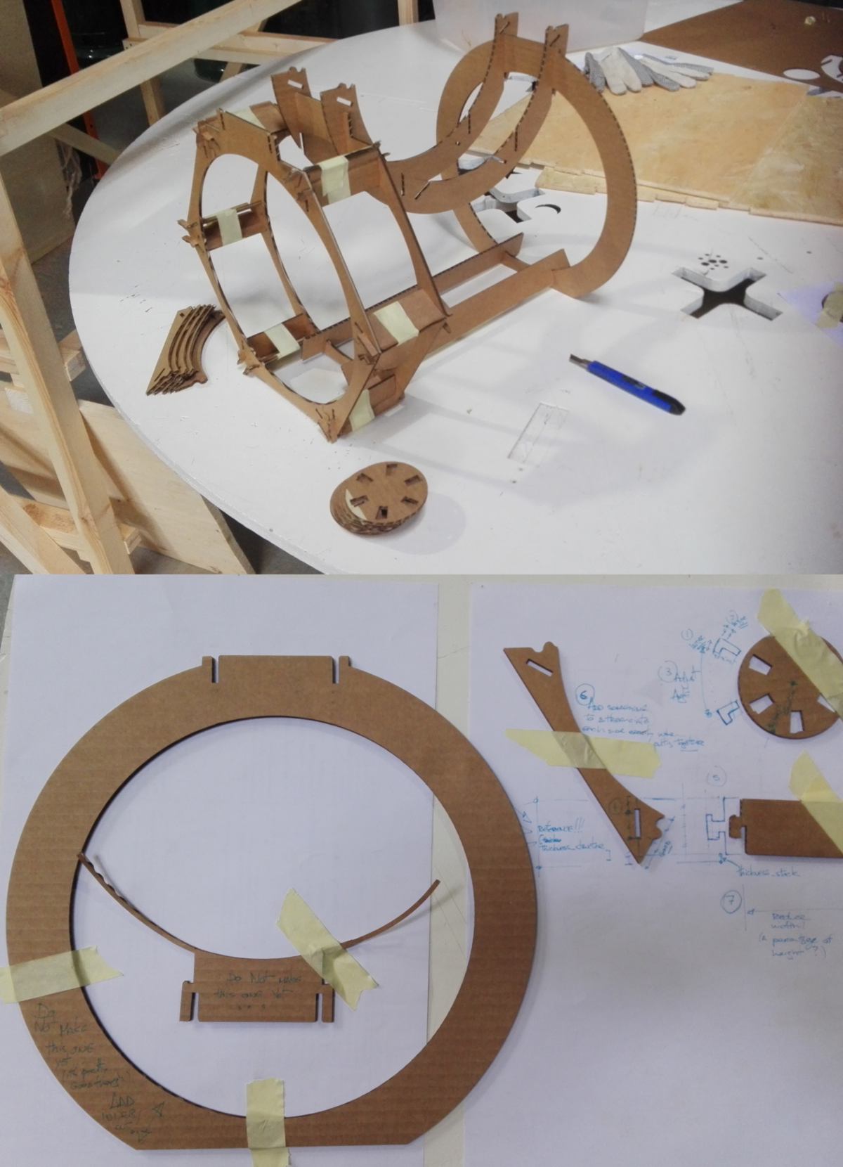
I go through several iterations in cardboard. The first one is functional but bulky, the second takes advantage of the lengh available between the legs of the green walls to store more compost. The third one is an attempt to use the compost as an extra weight to ground the green wall, and embeed the shape into the overall design. To be continued :
On another note, I seize an opportunity to apply for a scholarship for a Master in Design for Emergent Futures at IAAC. By doing so I discover Space 10 and their many projects including the Growroom , an open source design to grow food :
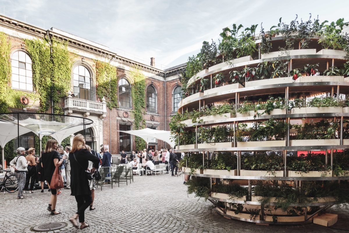
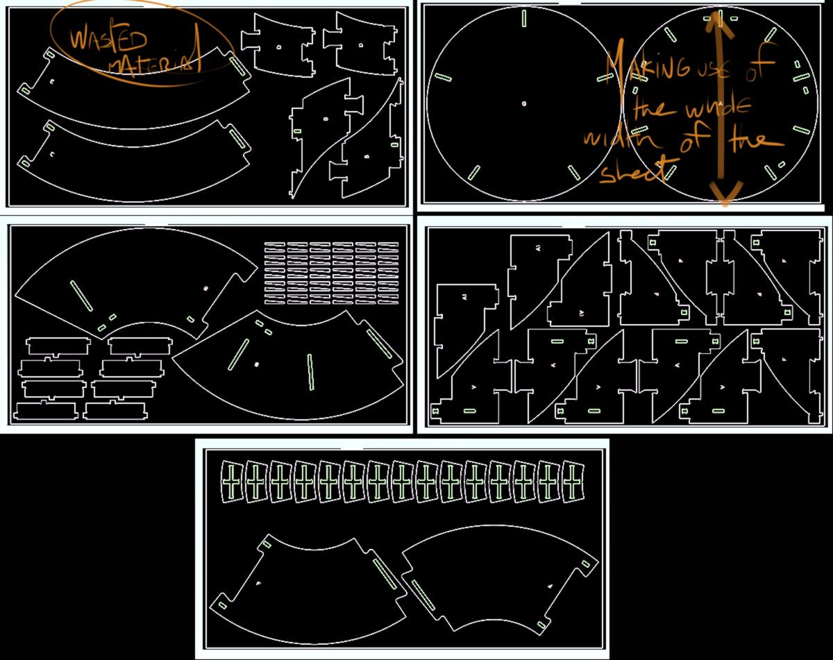
Looking at the manual, I discover it will take 17(!) sheets of plywood to put it together. I study the way the designers Mads-Ulrik Husum and Sine Lindholm have nested their pieces in the sheets of plywood. For the bottom and top pieces, important structural components, they designed the shape according to the width of a sheet of plywood, so that it could be made out of a single board without joints, to ensure its sturdiness I guess. Then the other pieces were laid around to loose as little space as possible. The curved horizontal shelves are divided in shorter parts so as to fit more on an single sheet. The presence of curved shapes makes it difficult to use the plywood without wasting material :
Overall, this is a very big ball of plywood, and some addition would be required to take into account the need for water and nutrients. The communication around the project is very well-done.
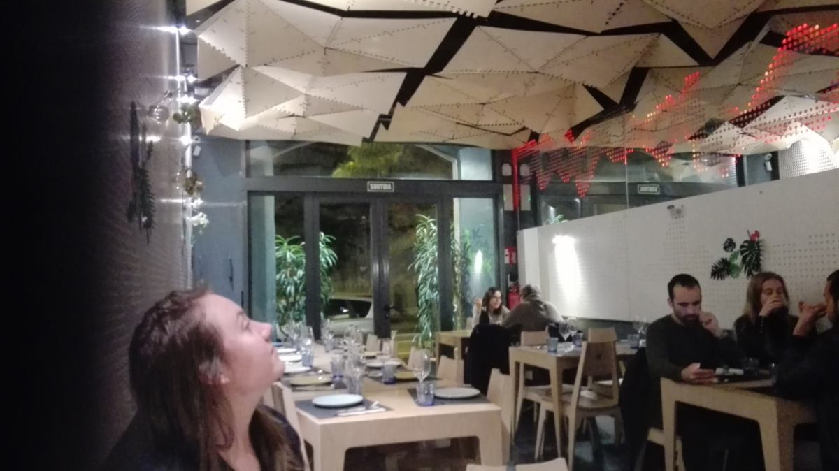
Another well put together project incluing a lot of CNCing is Leka, a local, open-source restaurant. Design of furnitures, clothing and recipes are available online. It was designed here at Fab Lab Barcelona and the restaurant is two blocks away :
A whole two-people table fits neatly on two sheets of plywood. Not only the cutting files are shared, but also the (impressively complex) grasshopper files and extra information about the design. When they say open source, they mean it :
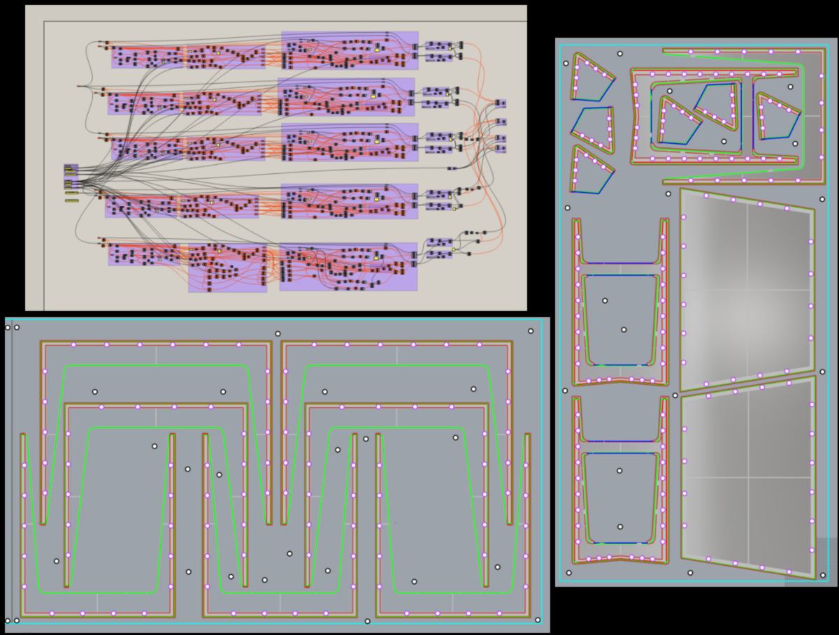
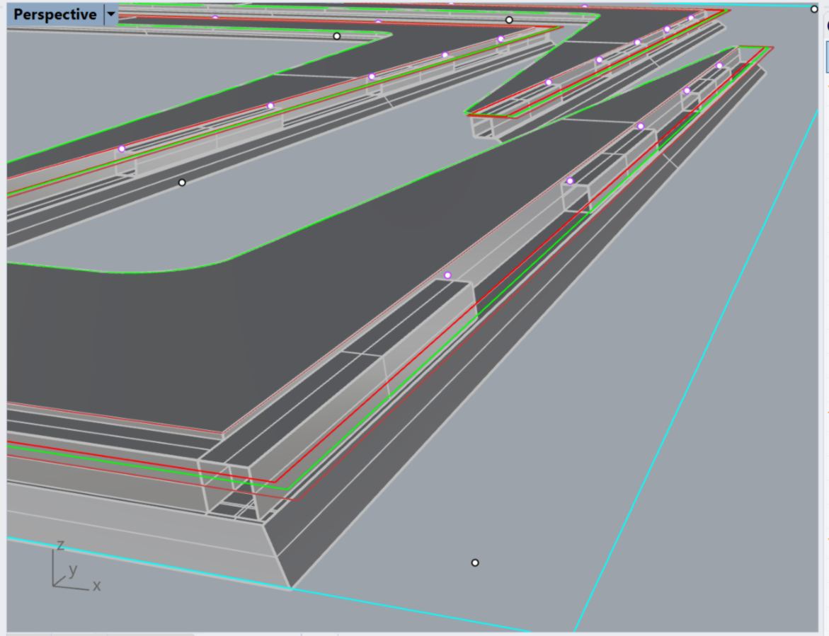
This design uses a very smart press-fit joint, invisible once put together :
Before the end of the day I craft another idea for the wormfarm, but it now seems overly complex and stylish.
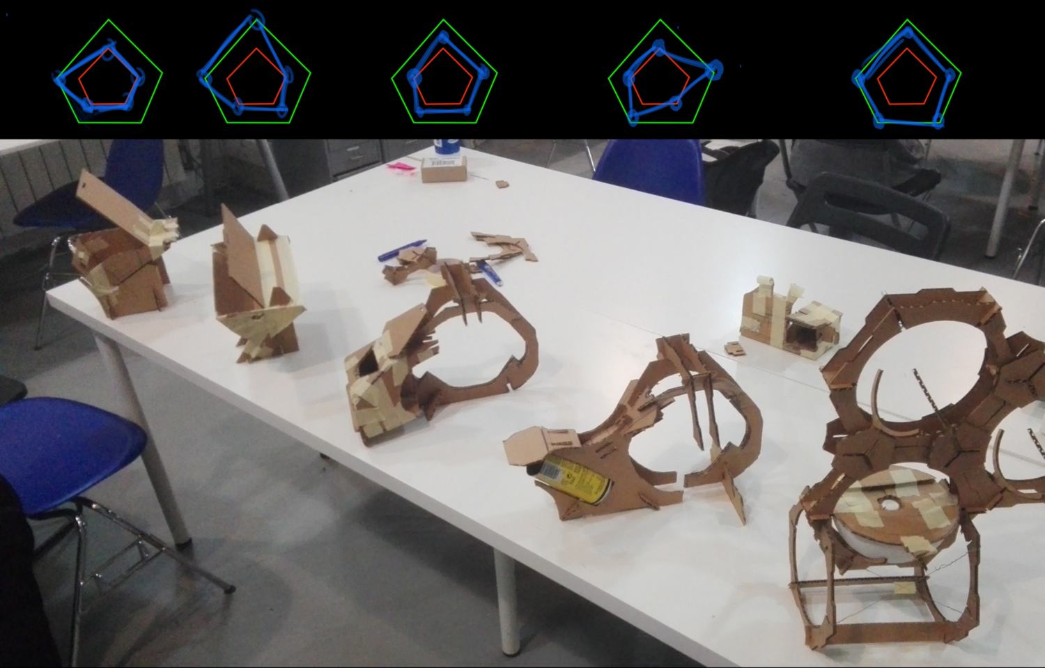
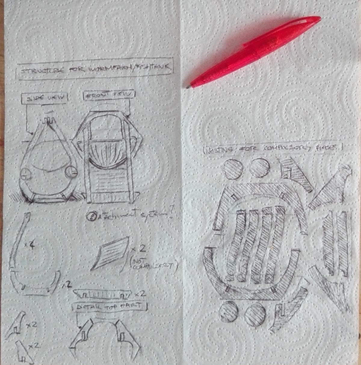
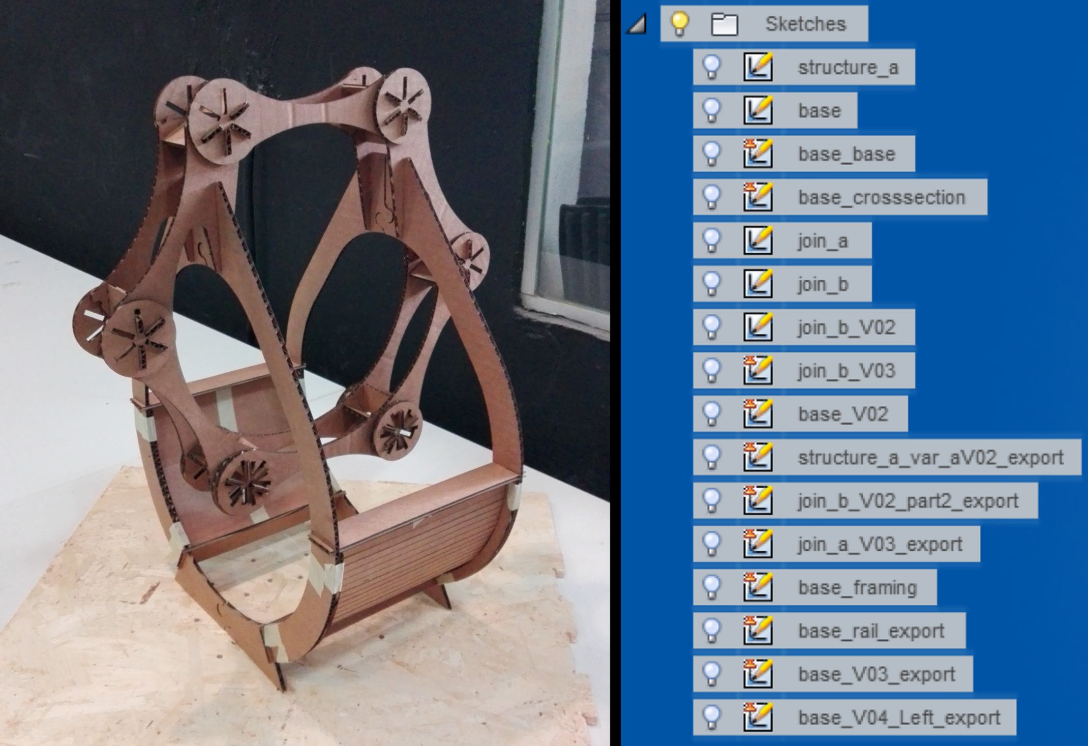
13.03.18 /I have finally finished prototyping the cardboard version of the wormfarm. Below is what I will finally turn into a digital design :
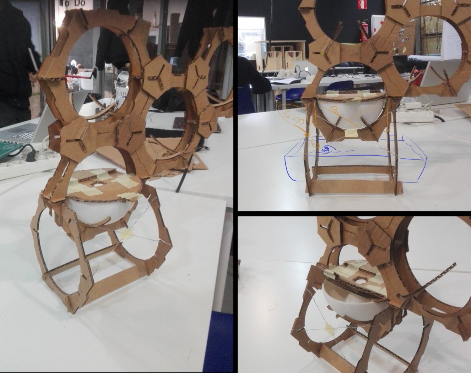
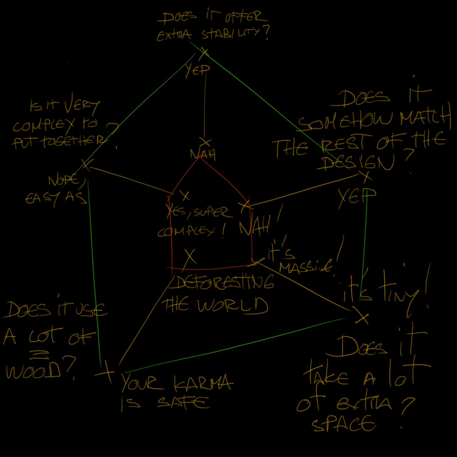
I made this choice after an analysis of the prototypes I have developped over the last few days:
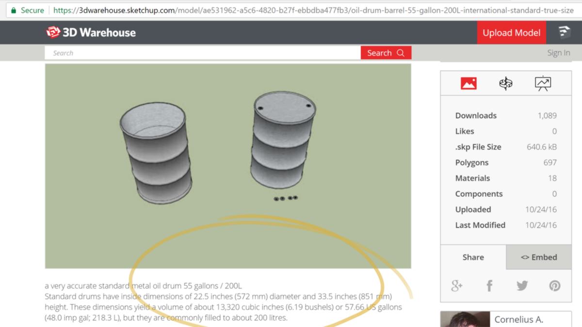
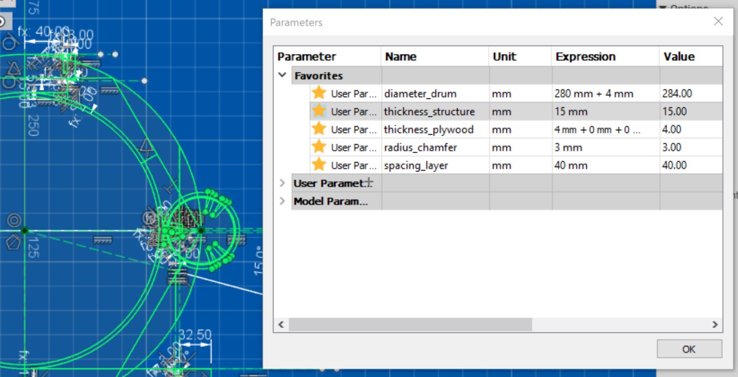
I can now base my design using the dimension of a standard 200-litres water drum. The drum is the only element I have no control over :
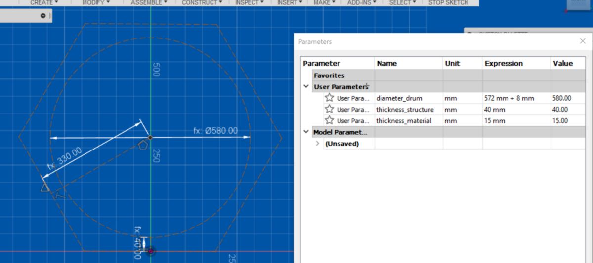
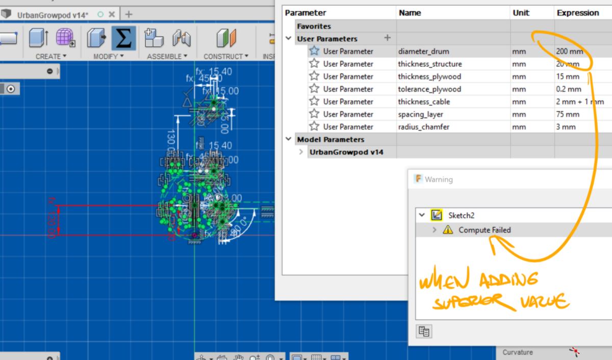
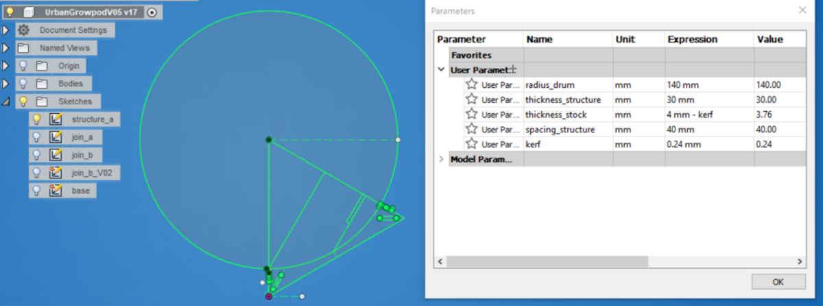
I set up parameters for dimensions that might change over time. I encounter an error while testing them out. Fusion is not able to compute a parameter change. I revert back to a version old by three versions and carry on.
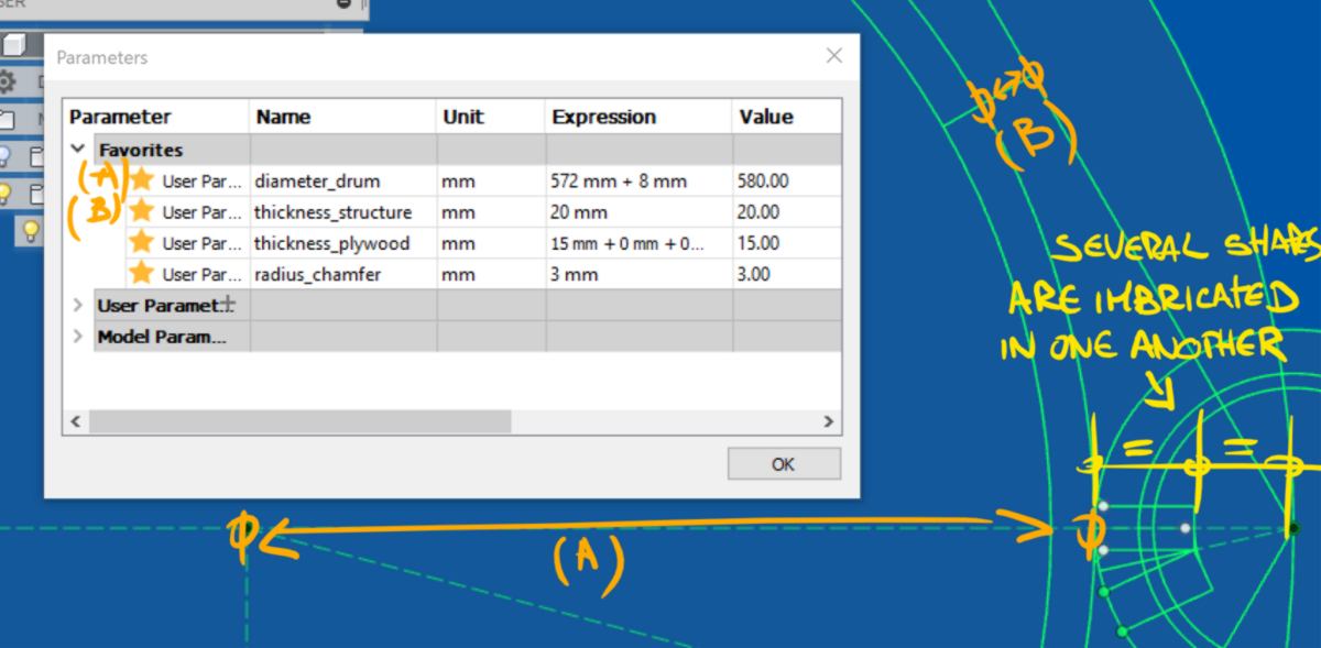
14.03.18 /I carry on with the design. I am saddened to discover that Fusion cannot use driven dimension as a parameter. This impacts me a great deal since I cannot select then divide a value directly before using it for another piece. I have to mix up user parameters with constraints, making the whole process more intricated. In order to use the same measurements, many shapes are overlapping :
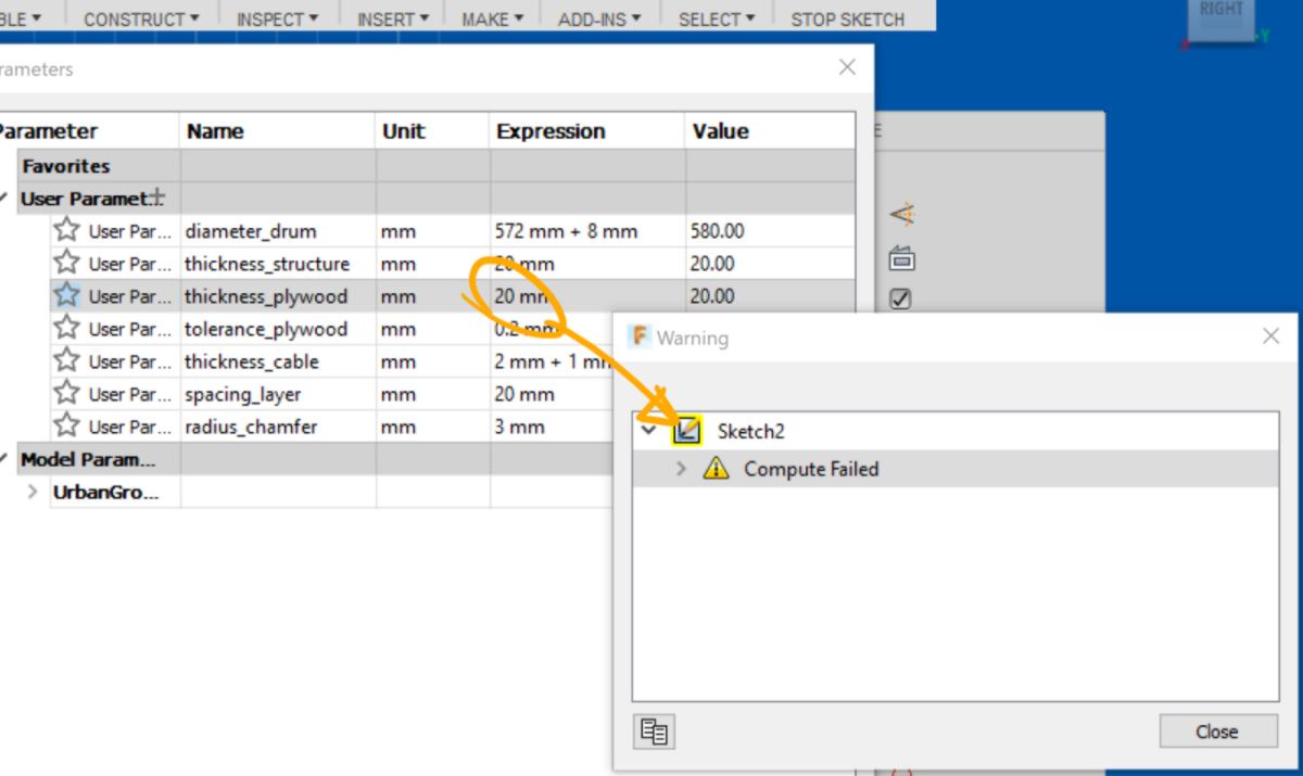
I also discover another computing failure when changing the diameter of the drum (when trying to make it wider, Fusion fails to compute. Going for a smaller value is fine). This problem goes as back as 6 versions ago (V08 for reference).
I look for exit strategy searching for ways to import my design in more powerful softwares like solidworks in case this parameter has to be scaled up in the future.
I also think that the way I constrained the design has a big part to play in the computing failure. I have a closer look at the warning given and make constraints less dependant on eachother. I re-design my shapes and constraints, making it lighter by using a single point as a reference, and designing only half the shape required. I will mirror the rest once the design is turned into a body. I end up with a working sketch, with many pieces operlapping :
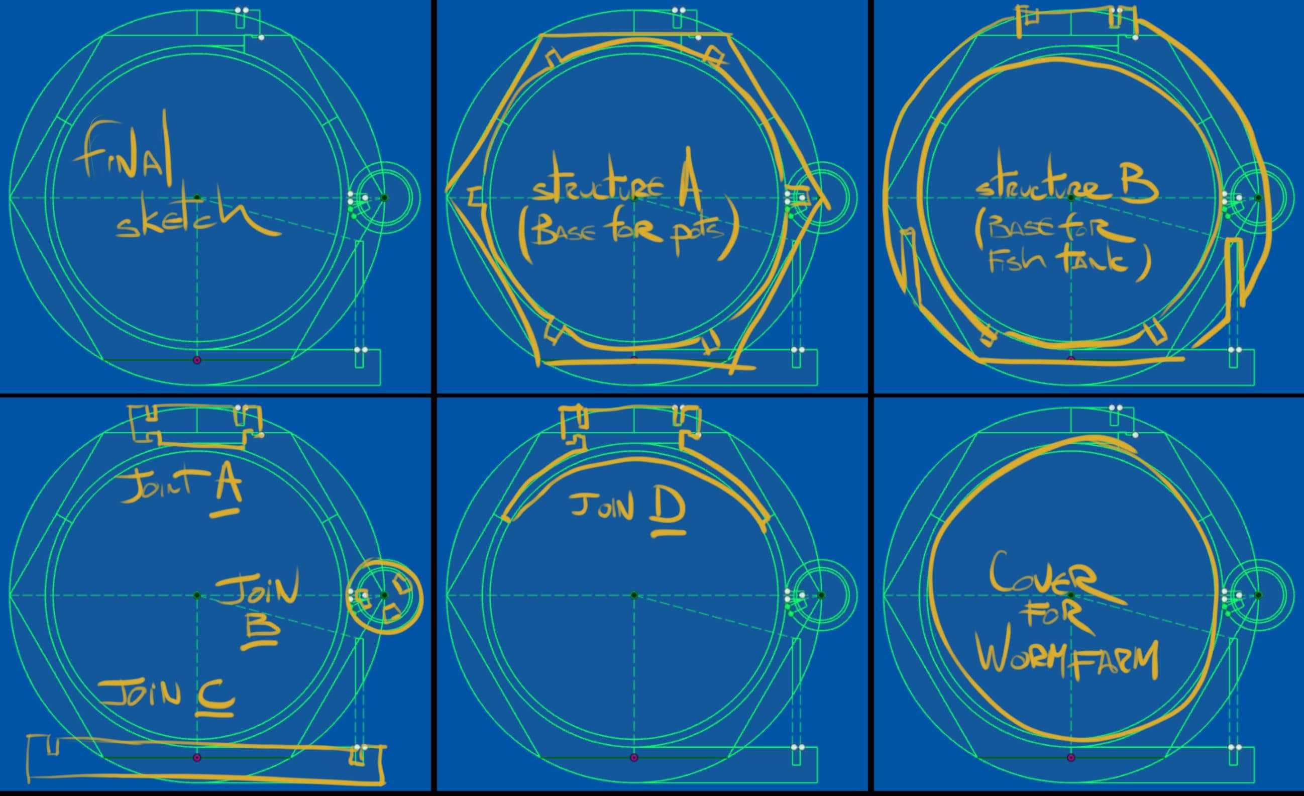
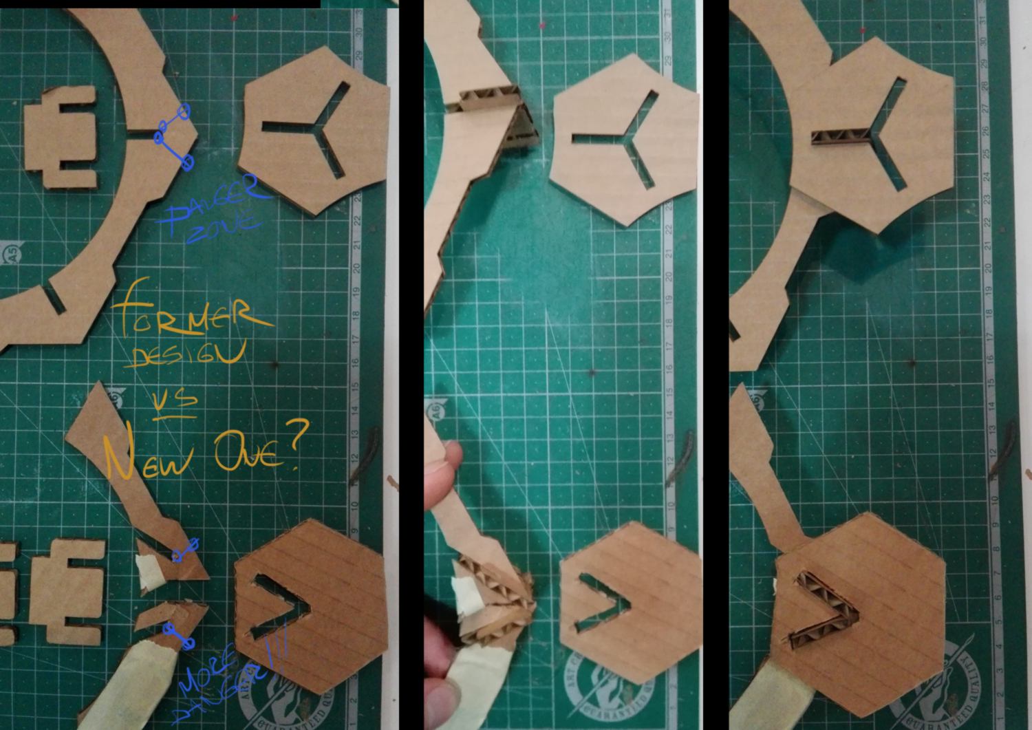
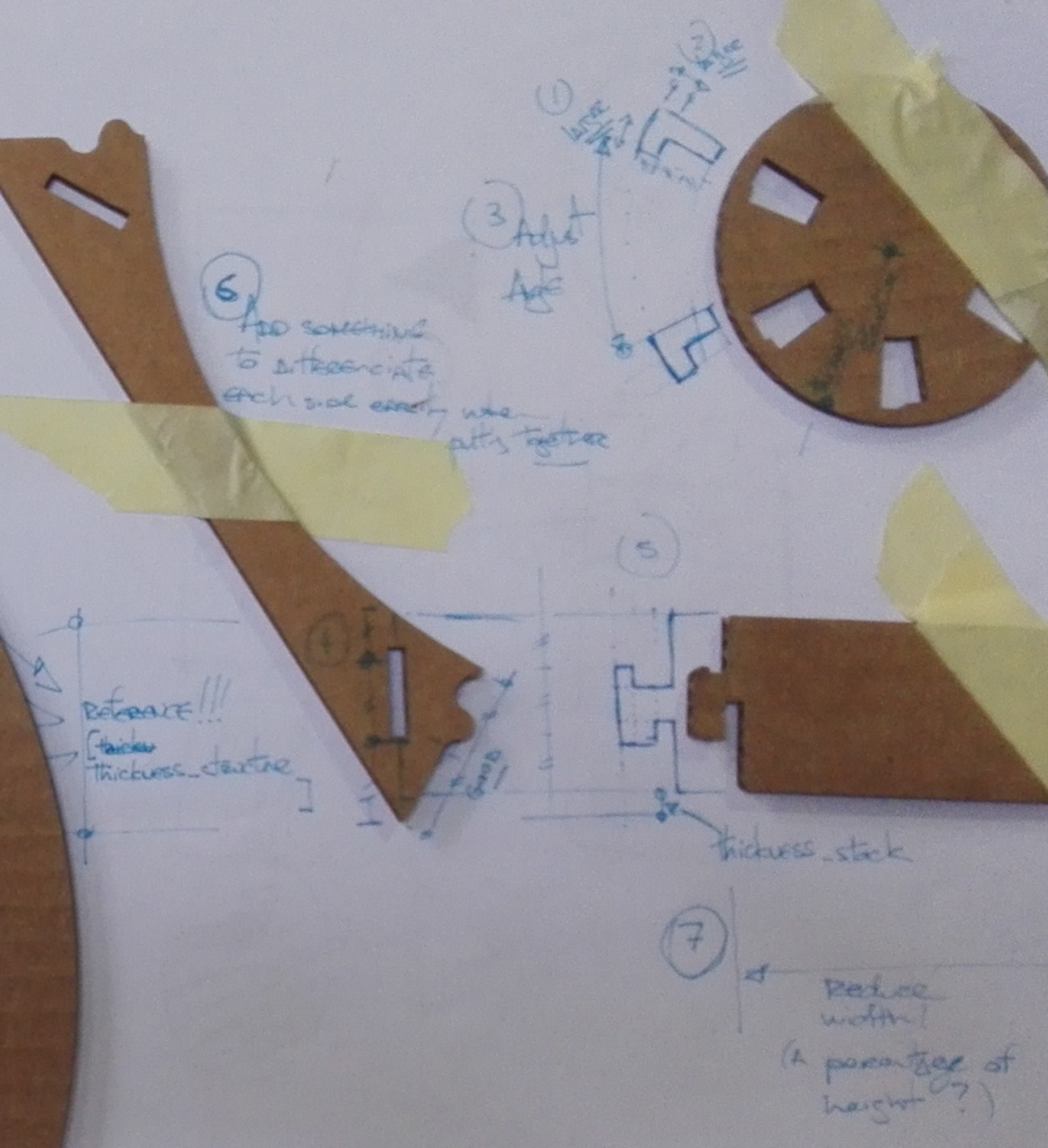
One issue that comes to mind when looking at these shapes is the amount of wasted material generated by it. The shapes are big circles with small joins and I wonder if I can nest them efficiently, or if I have to break these large circles down to fit more of them on one single sheet :
The difficulty in breaking these shapes down into smaller pieces is the design of a new joint and the loss of structural resistance that might occur from it:
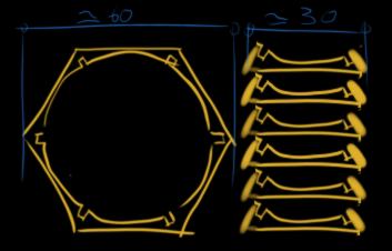
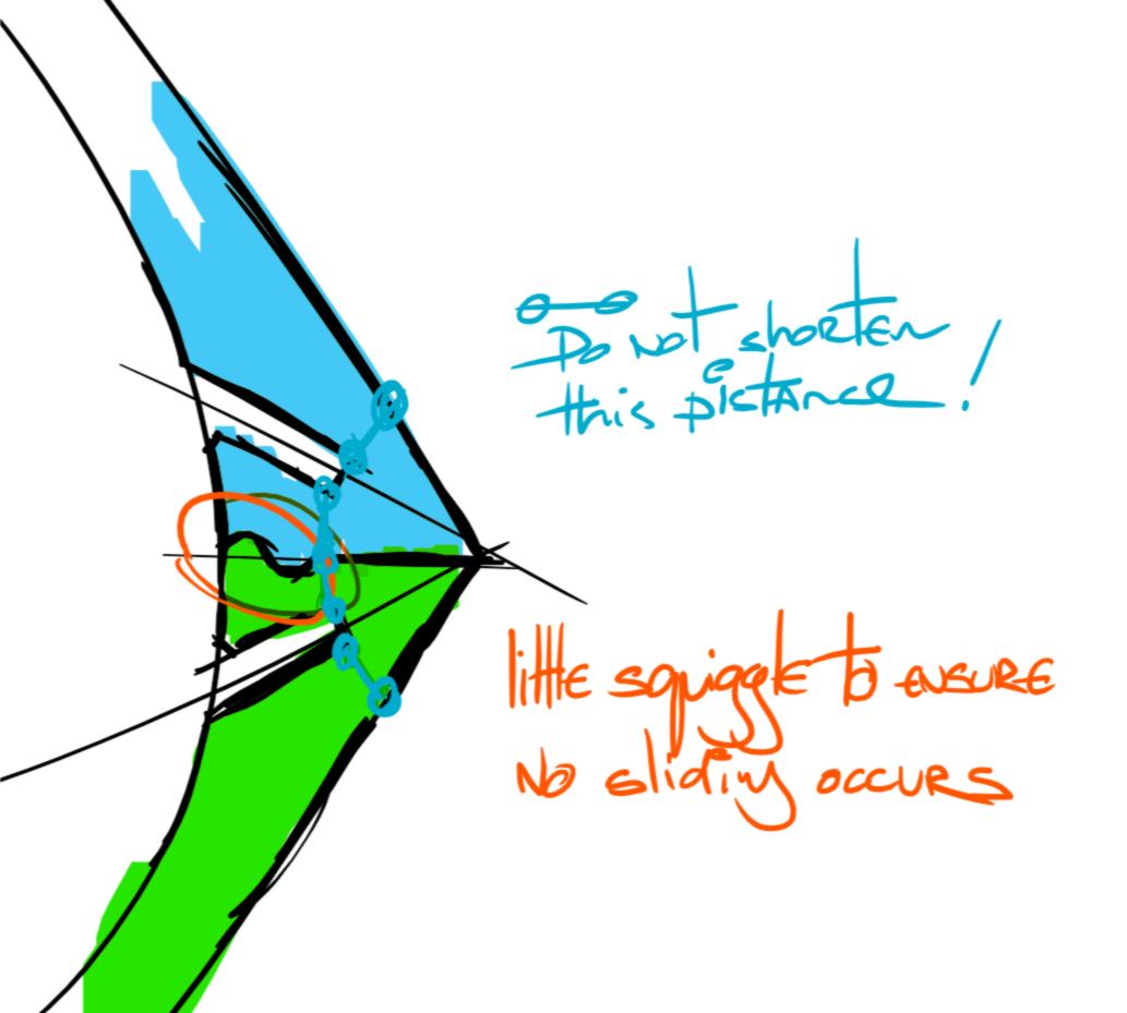
I add a little wriggle on the flat surface between each piece to avoid sliding. I add rounded shapes so that the end mill will be able to trace it accurately, and will not struggle with any corners :
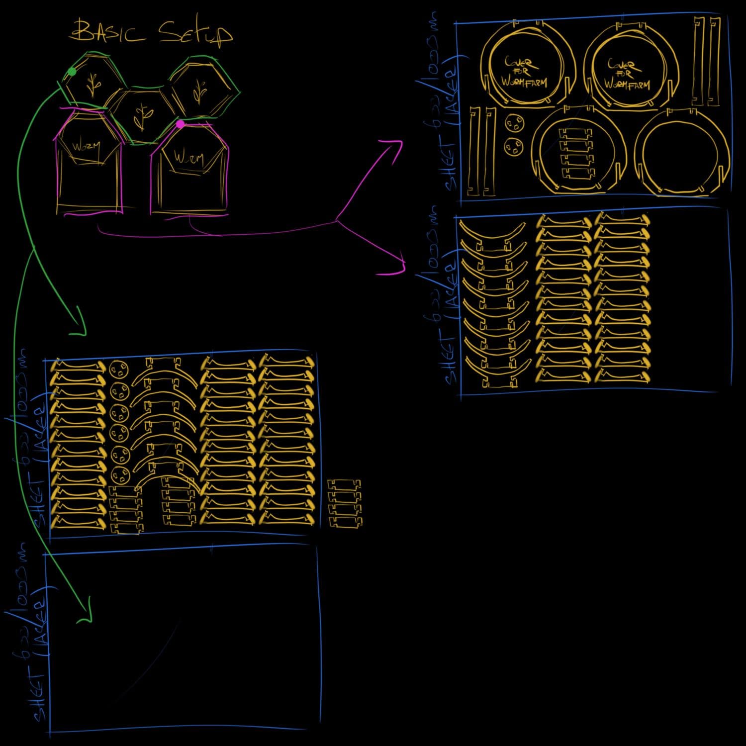
For testing purpose I am going to cut out a 1/2 reduced scale model in cardboard, using a drum with a diameter of 280cm. A 1/2 reduced-scale model is very conveninent since the cutting plate of the laser cutter is 600/1000mm, very close to half the size of the sheet of plywood I will end up using.
Half way through the process of extruding pieces out of my matrix, I notice that, after resizing the model, the constraints I created for the joint are incorrect. I go back a few versions to correct them :
Here is some good news : sometimes when a parameter is changed and Fusion display a failed compute, the fix can be as simple as modifying the parameter one unit at a time, until reaching the correct value. For example, I tried to modify the thickness of the material straight from 15mm to 4mm, and Fusion displayed a failed compute. But by slowly going to 9mm, then 7, 6, 5, and finally 4mm, it works just fine.
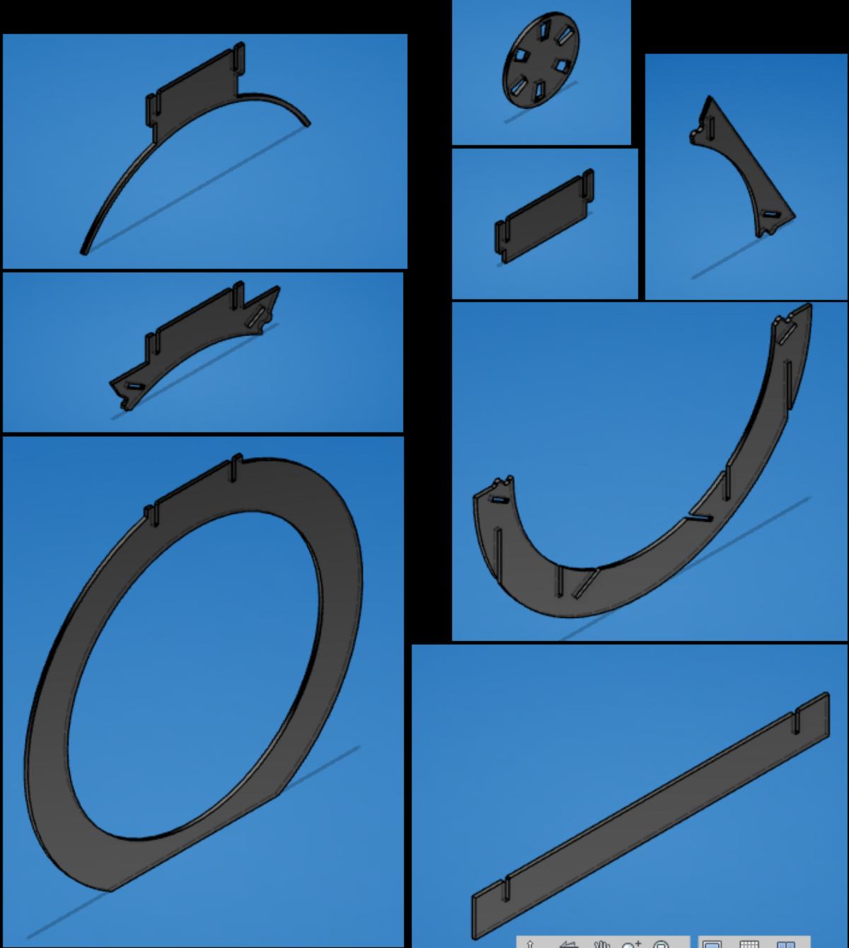
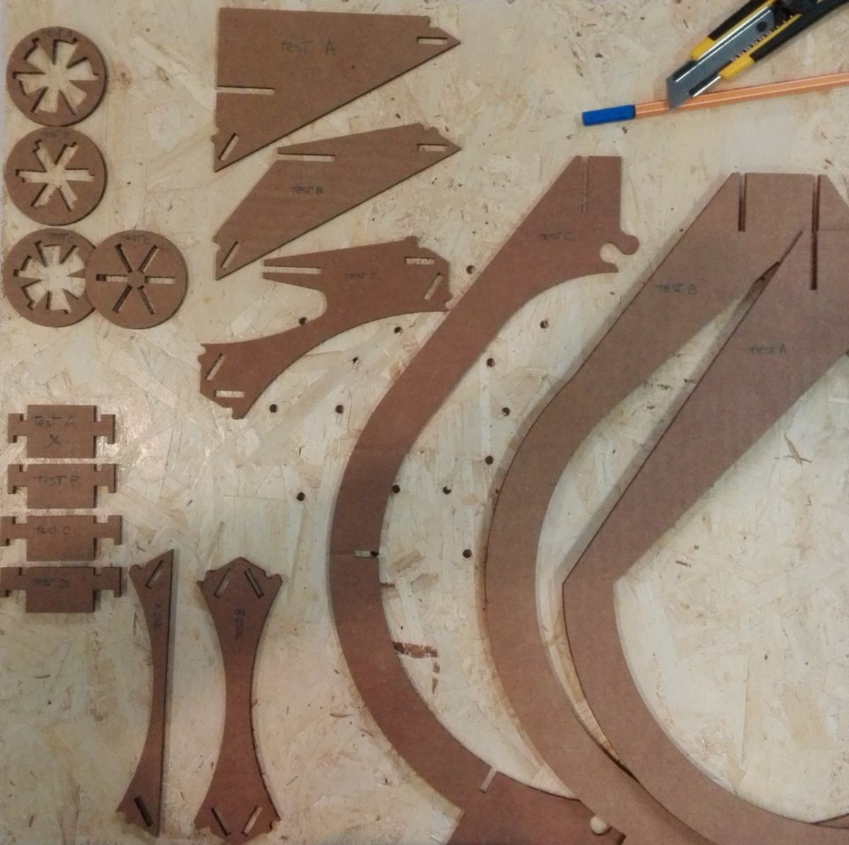
I end up with a catalogue of shapes, some that I planned on making, other that I just find interesting and want to explore:
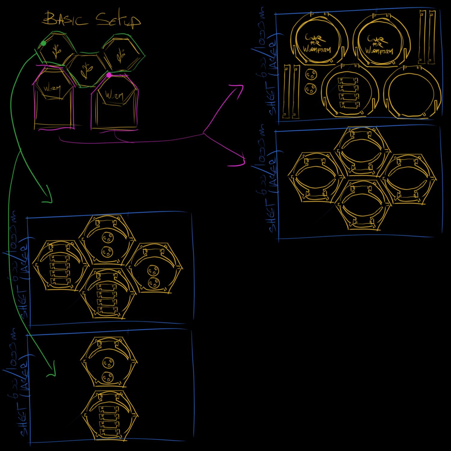
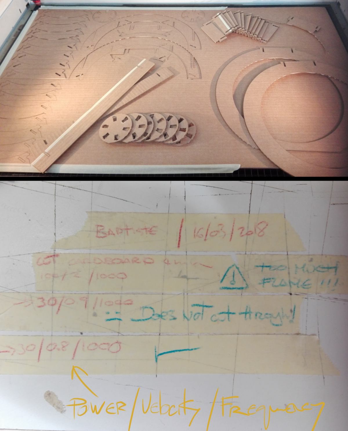
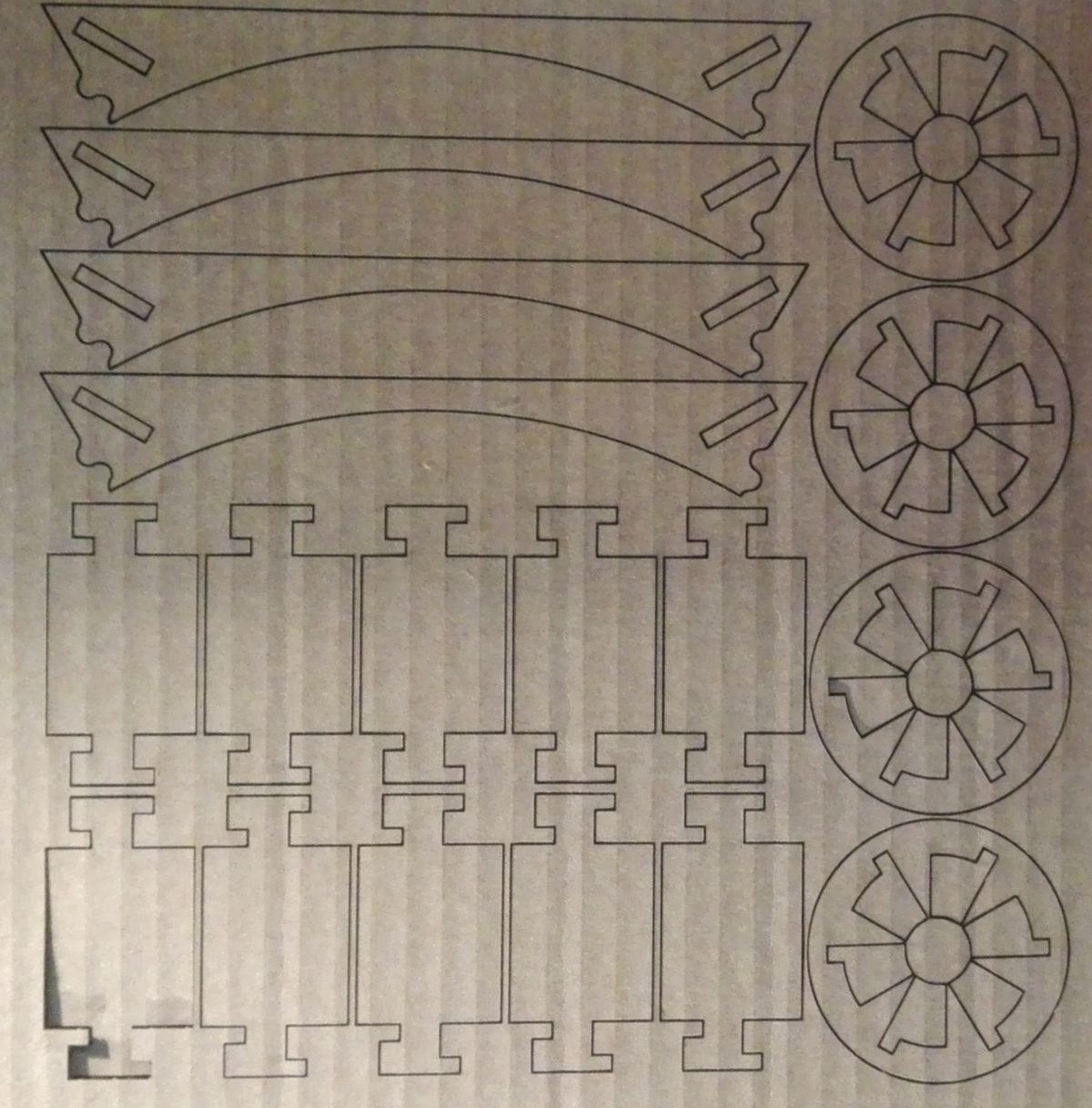
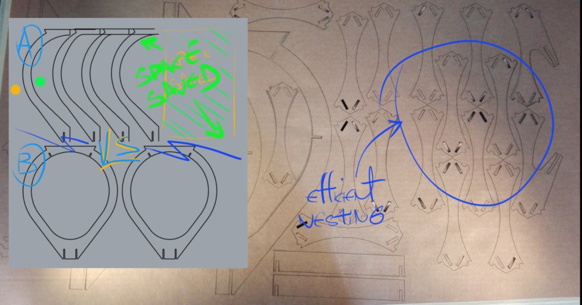
I nest them in a sheet for laser cutting, testing out different options to save as much space as possible :
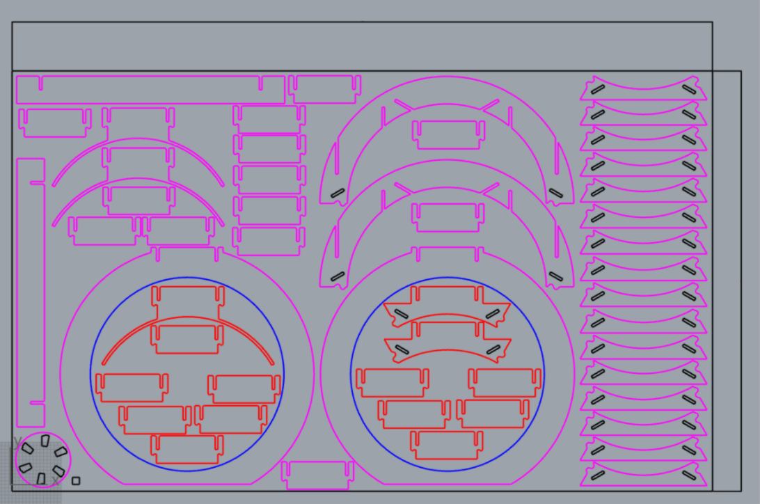
On the right-hand side, I was able to stack 16 structural components. Since it takes 6 of them to create an hexagon, I have 2.6 hexagon in this column, which is 0.6 more than I estimated. If the construction happen to be sturdy, it might be worth the effort after all.
16.03.18 /Laser cutting all pieces prior to milling the design is very insightful. Many pieces need adjustment.
I also test out new settings for the laser cutter, trying to accelerate the cutting process by using the full speed of the machine. After a few tests, I have to reduce the speed to cut through the material. This is an issue since the cardboard catches on fire. I have to drop the power way down and then adjust the speed accordingly.
I use what I learned over the last few days to re-do the design in a cleaner manner, drawing a sketch for each pieces.
17.03.18 /I carry on laser cutting test pieces , focusing on a specific connection.
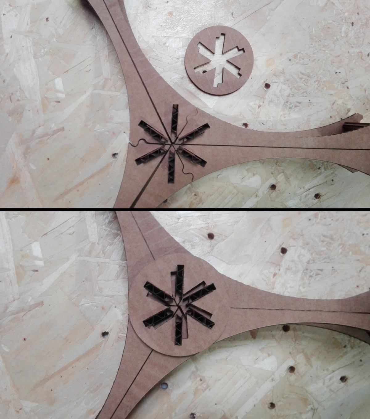
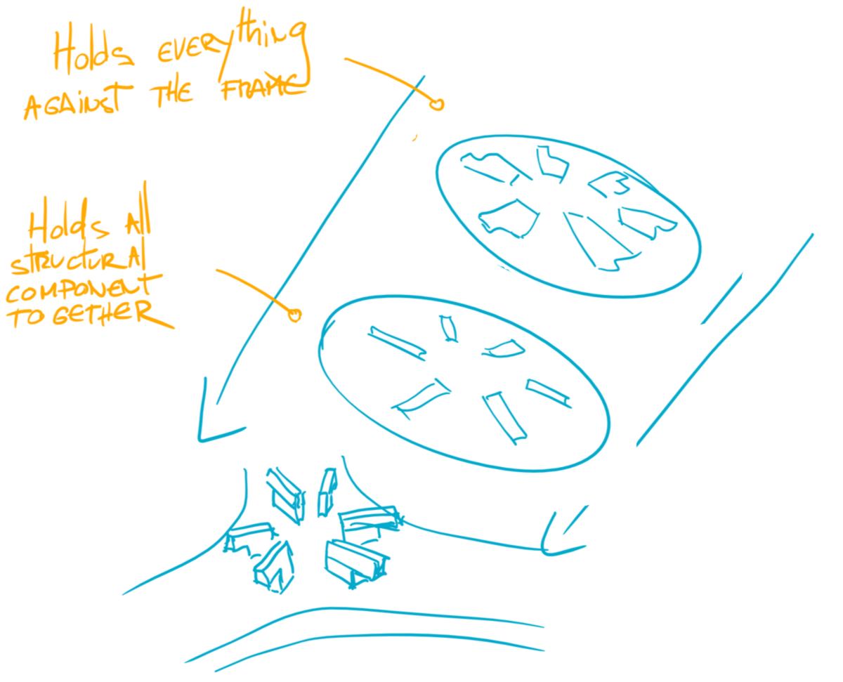
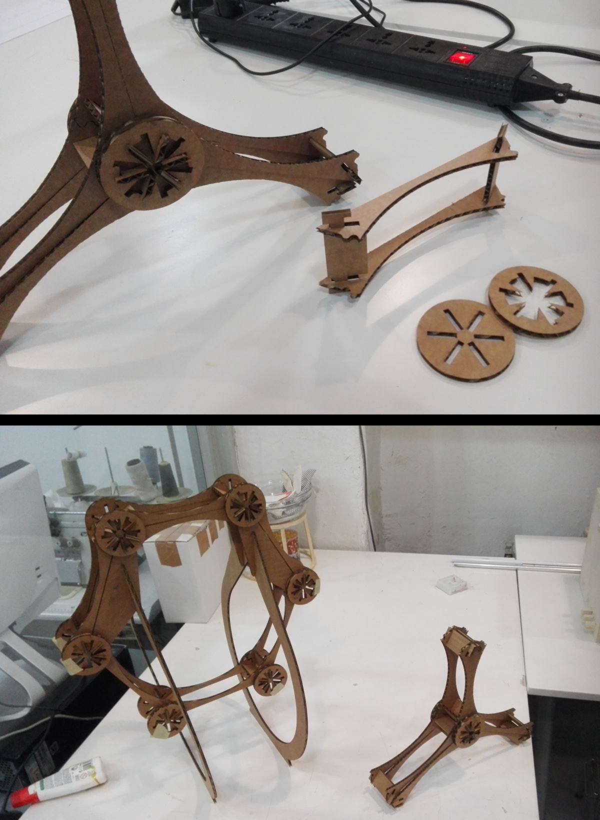
This connection is located at the corner of each hexagon. The hexagon is first put together, then an extra pieces comes on top and spins to hold the corners into place :
I go through many versions for each pieces to get a good fit :
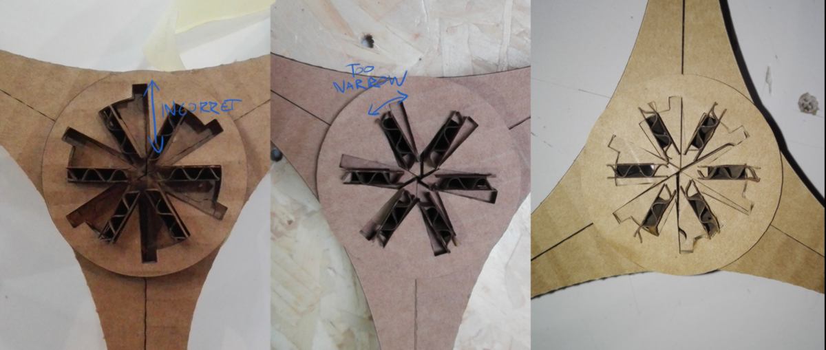
This spinning piece, even well adjusted, works only partially. The joined pieces still have too much room and slides sideway. Thanks to a student passing by, an idea comes to me : using both systems in conjunction, as described below :
Since I must wait until Monday to get access to the CNC machine to test it out on plywood, I begin to re-design the base, which will hold both the wormfarm and the fish tank. I do so considering the future nesting of each piece, trying to save material :
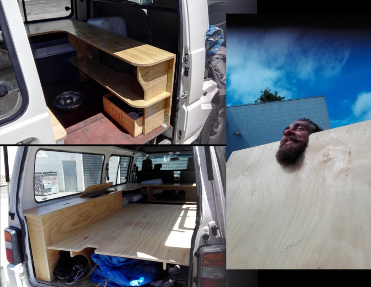
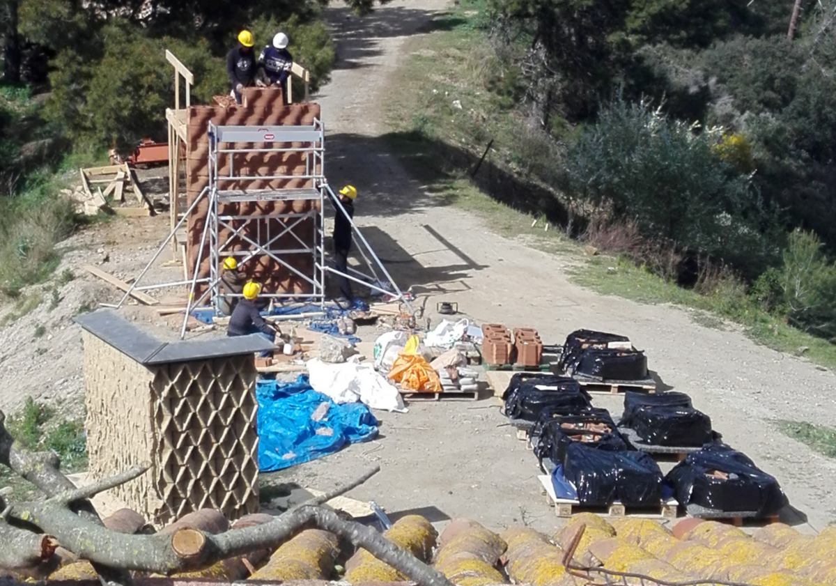
18.03.18 /I am back at Valldaura for a barbecue, and as usual, I scout around for some novelties :
19.03.18 /Tonight FabLab Barcelona inaugurates the Distributed Design Market PLateform Project which should allow, at the end of this 4 year-long EU-funded project, enable equipped workshops to fabricate and sell designs created anywhere in the world :
" The Fab Lab Network intends to educate society about making almost anything we need. Using digital fabrication as its main focus, the network promotes the idea of distributed manufacturing. With this model, designs can be sent to the other side of the planet, modified and made on the same day.""
At the very Same time Carl, the director of Fab Lab Christchurch, is presenting the Fab City concept to the NZ tech innovation gate keepers, attempting to access public funding to make a more profond impact. New Zealand is geographically far away from other continents, but plywood as well as other materials are still imported from overseas rather than using correctly the many forests covering the country. I am seriously considering this distributed design market as an step forward. At the same time, it raises many questions : How will the designers get paid? Is a Fab Lab actually able to produce goods at a larger scale, beyond prototyping? How to ensure the quality will be controlled? I hope to go meet Daniel again at Fab Lab Berlin to discuss it with him.
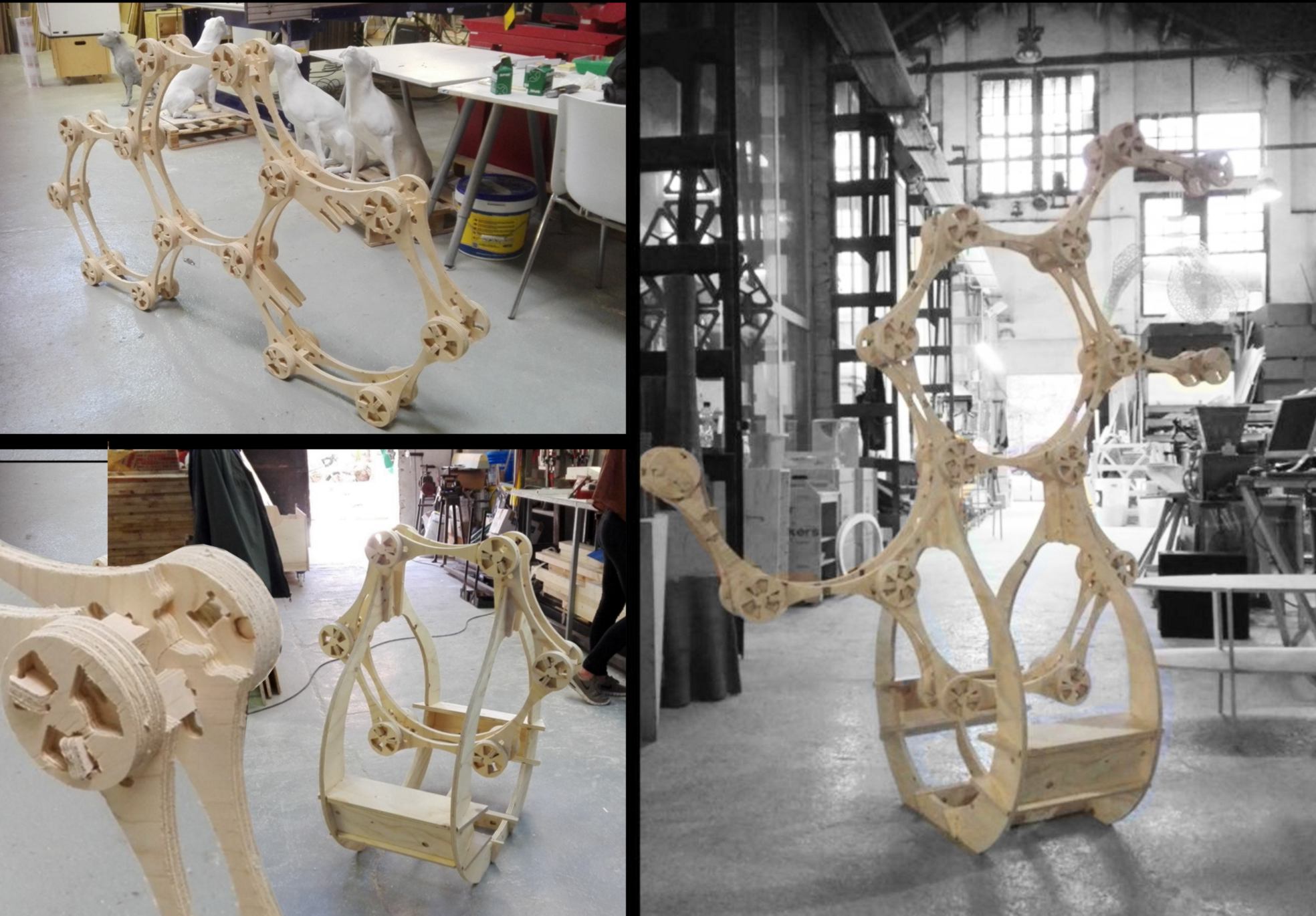
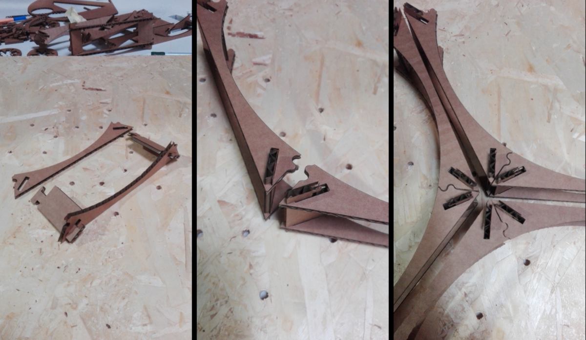
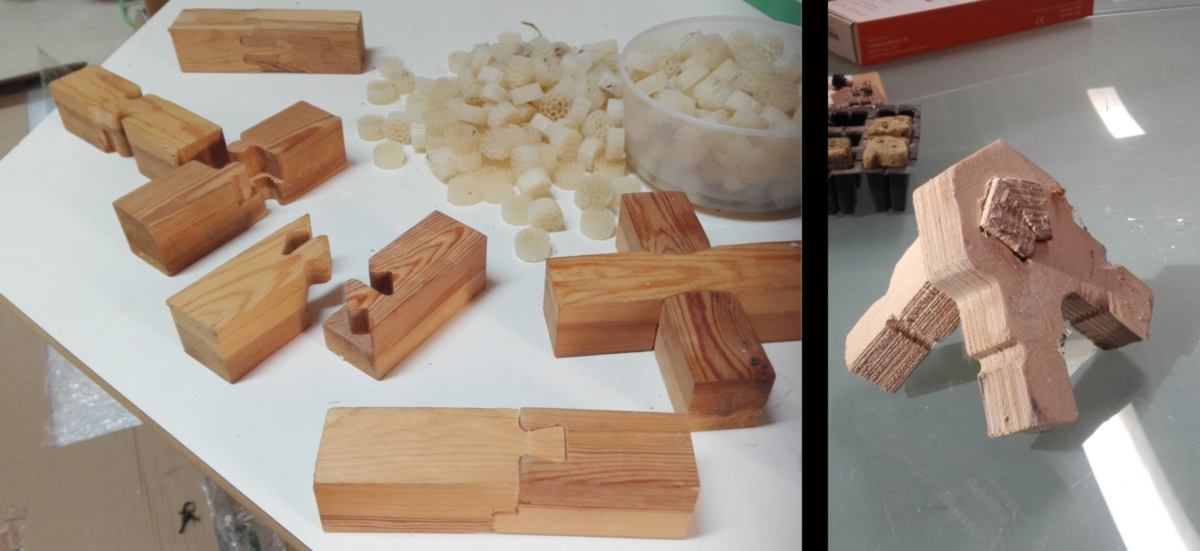
20.03.18 /The cardboard prototype of the green wall is completed to a satisfying level. Designing the base was an extra difficulty, but ensuring the sturdiness of the overall structure was important. I also looked at the best option to divide it in order to save space when nesting the design. Also, the main structural component, a simple bone-looking connection between joint has evolved to offer more resistance :
I re-design my shapes in a new file version. It is time consuming but I hone my design skills and keep my files more agile and able to take in new modifications. This time I add a new variable : the diameter of the end mill.
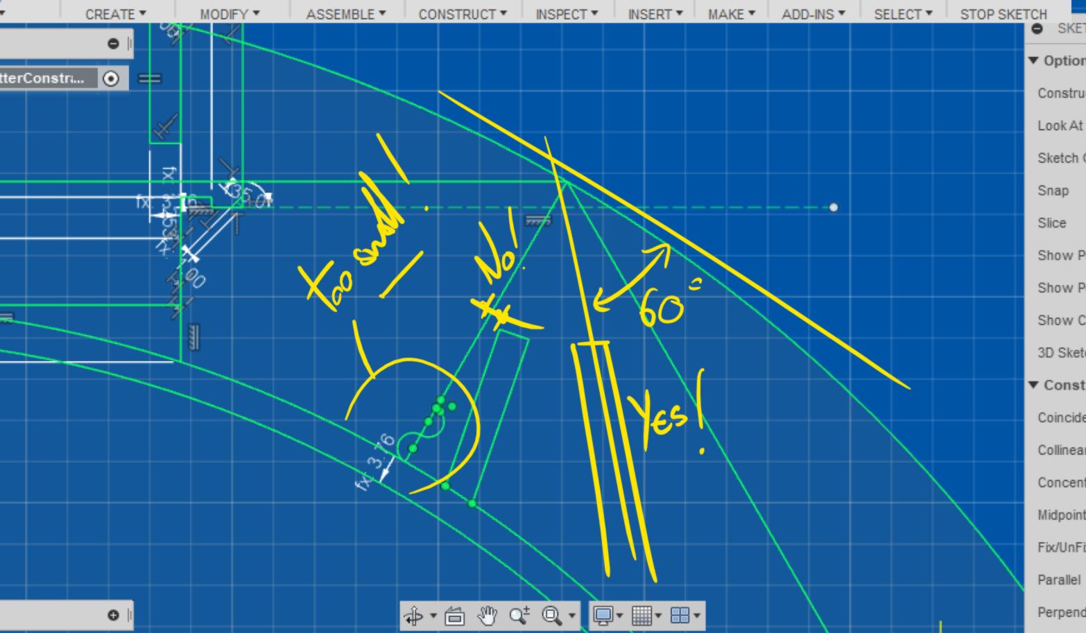
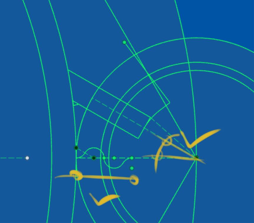
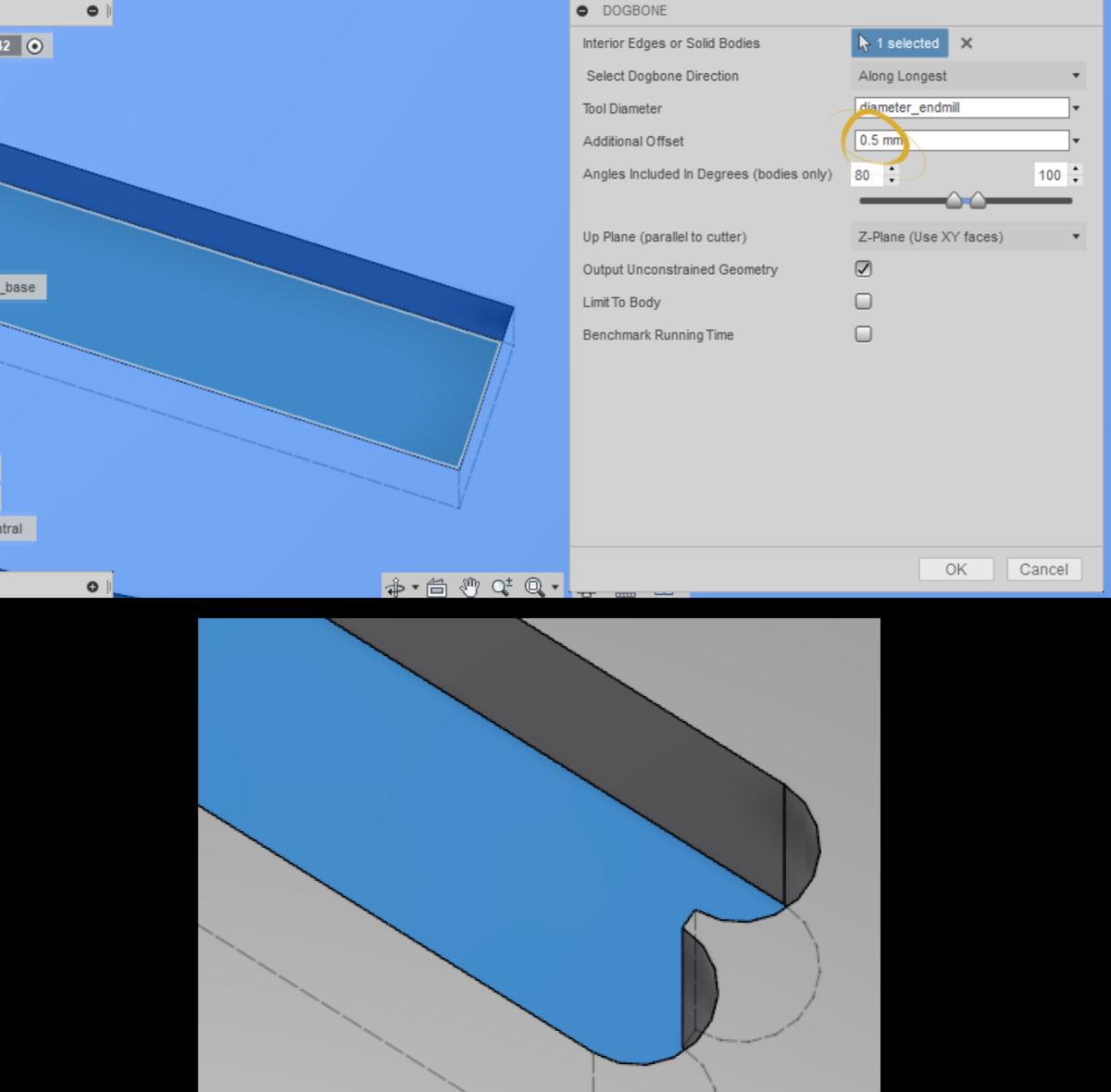
21.03.18 /I am setting up a test for all joints of my design, and modify it to make it CNC friendly. I gather along tools to help me set up dog bones in the internal corners of my design :
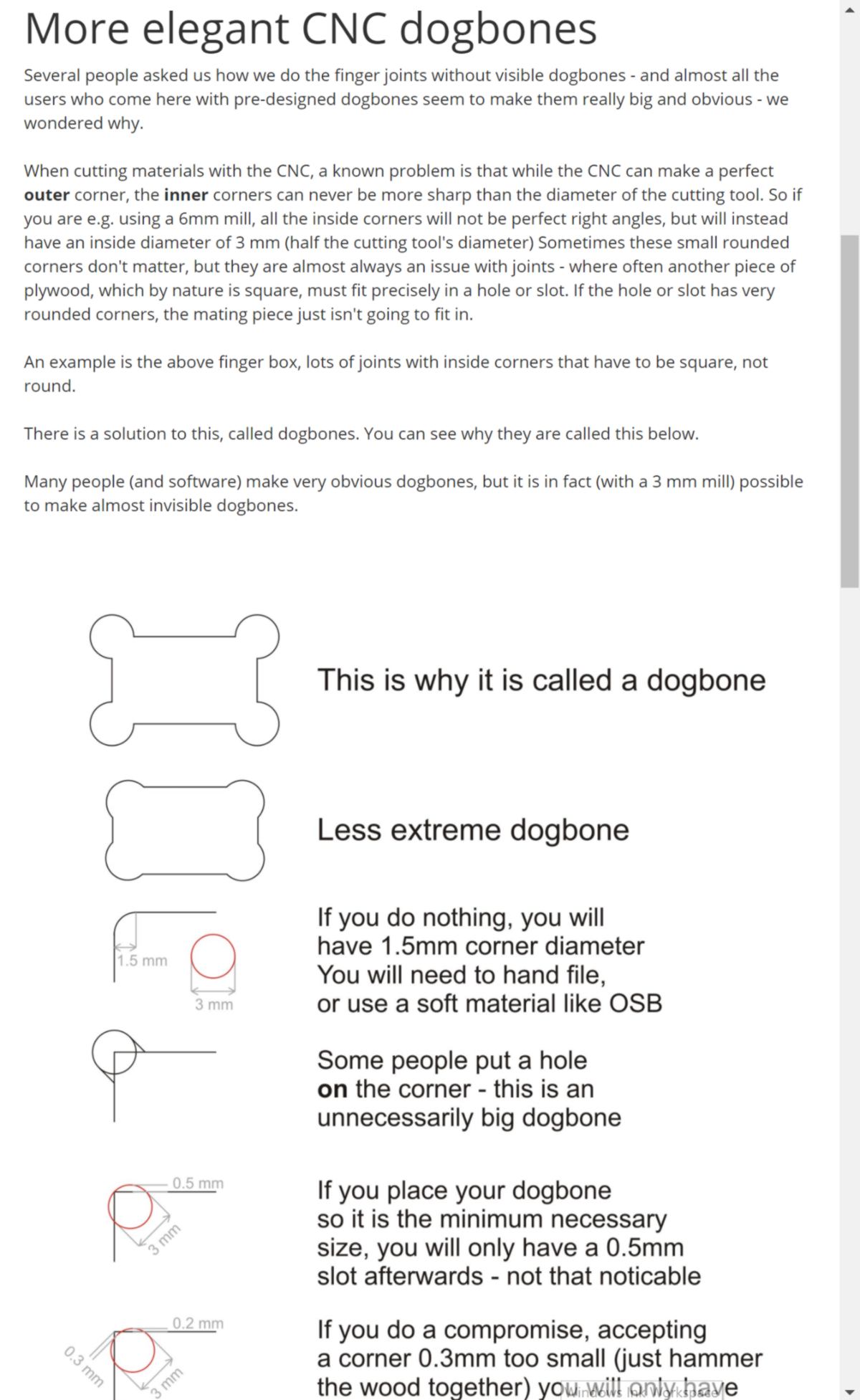
I set up the dogbones for my inner slots along the longest sides so that they will be hidden once both parts are fitting in one another. I add an extra 0.5 mm to the diameter of each holes to make sure the end mill keeps moving along :
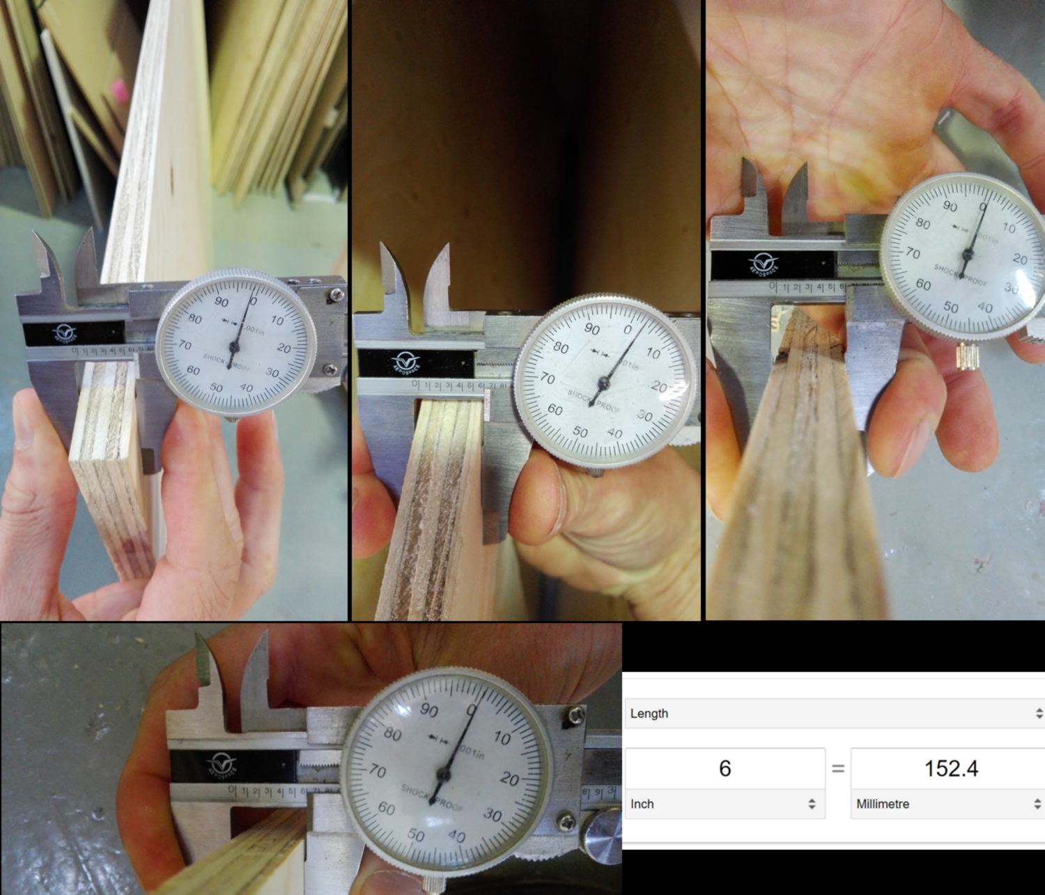
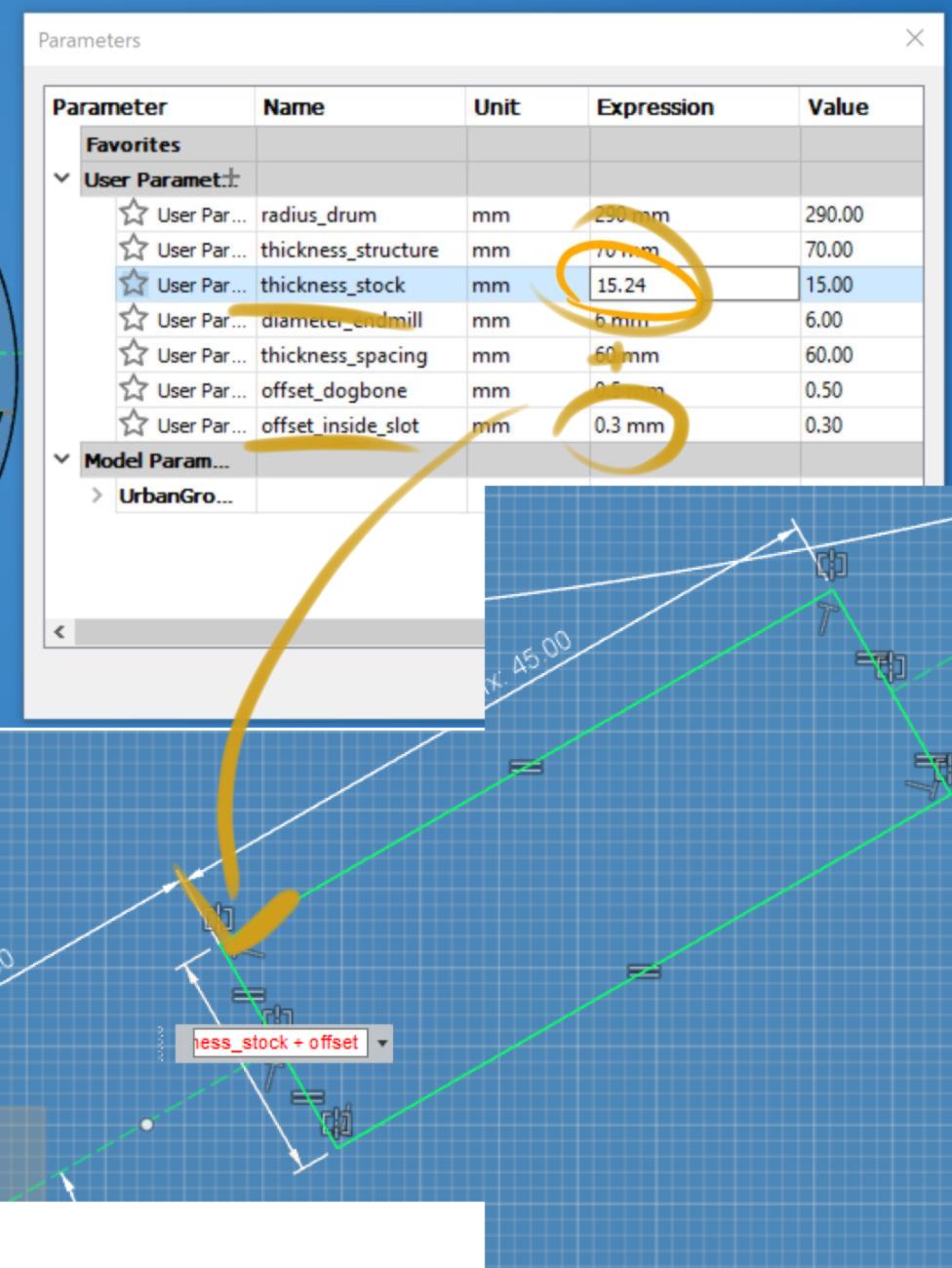
Before applying this to all pieces, I will adjust the offset for inner slots. I have been recommended a 0.25 to 0.3mm offset overall (0.125mm to 0.15mm on each cut). This has to be added to the width of the slot. I go ahead, select a piece of plywood and double-check its thickness at each corner. I will change the value of my stock in my file, then add this offset to it :
I prepare a test for all joints in Aspire:
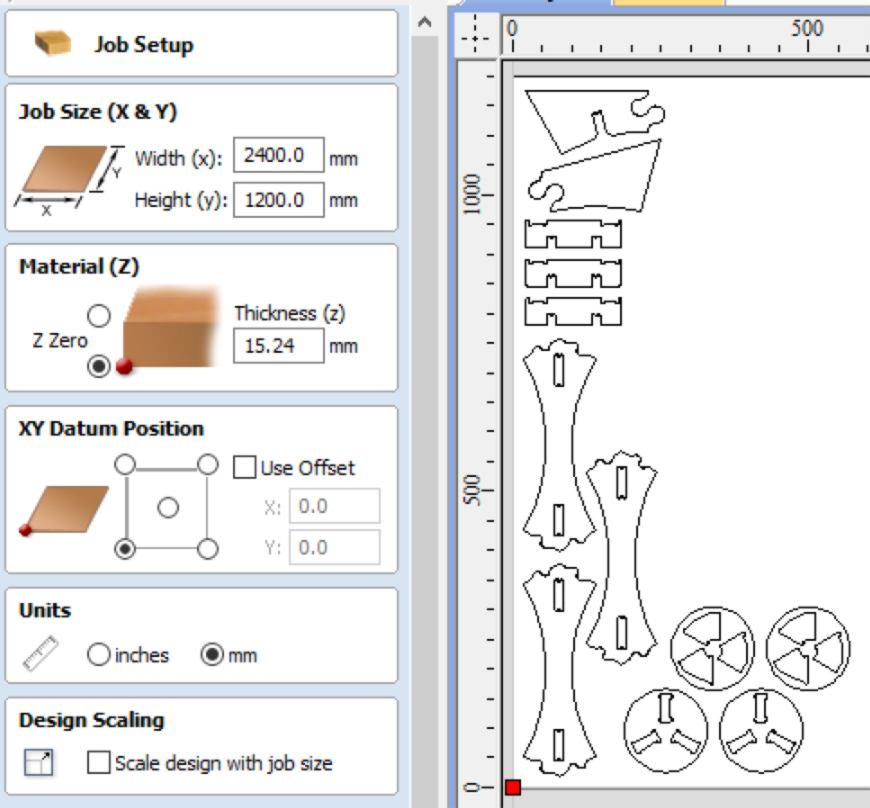
I am setting up three toolpaths : a "drilling" for the screws, a "pockets" for the inner slots and an "outline". In the past, I have only used the basic options of pocket and profile toolpath, and I wish to dig a little deeper in the options this time. I dig into the help section to find answers :
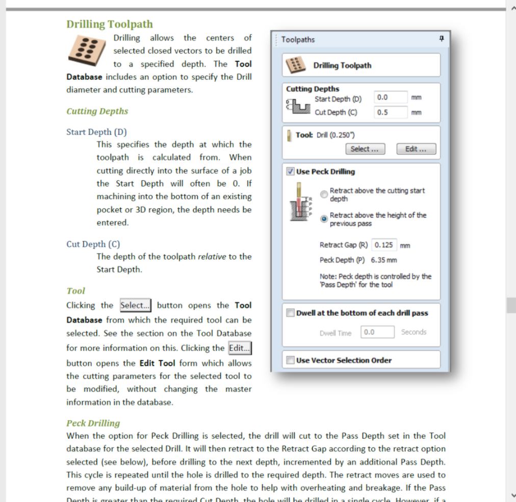
I set up my vectors on three separate layers, then select the type of toolpath required. In the past, I have been recommended to use climb rather than conventional cutting, but here the opposite is the norm, so I will go ahead with it and see what the result is.
In the past, I have also forced the end mill to go slightly below the thickness of the material to ensure I was going to cut through it. This time though, I plan on setting up the height from the bed of the machine, and I should be able to drill perfectly through it. Also, the type of end mill we have been provided tend to lift the material, which should help cutting straight through.
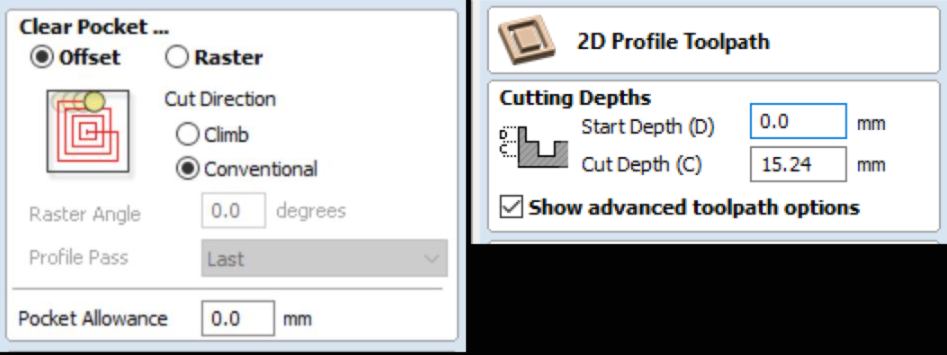
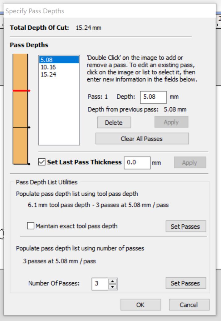
I do not need any particular finishing touch at this stage so I leave the pass depth set up by default :
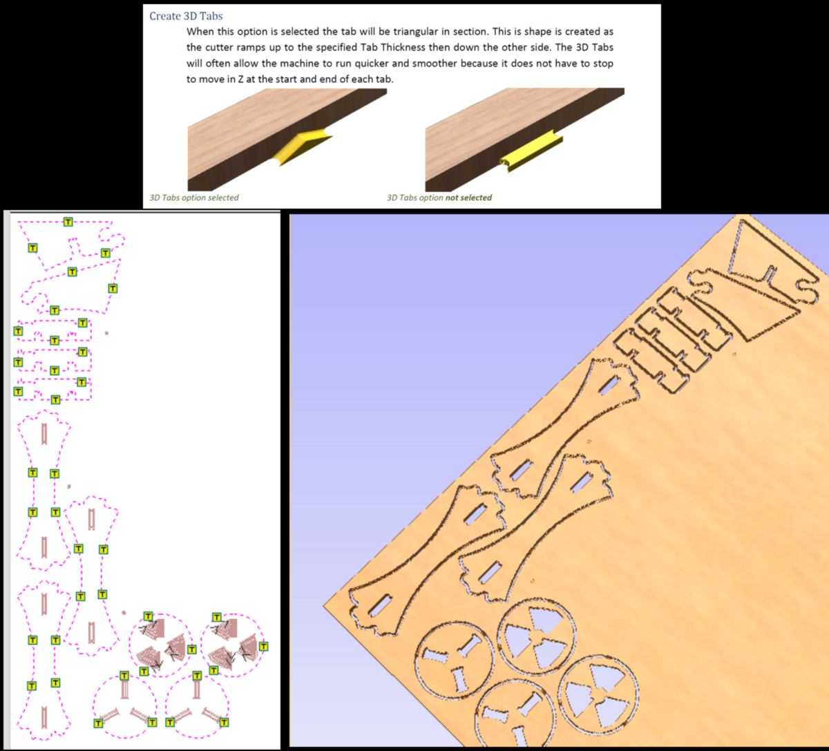
For the profile cut, I need to add some tabs to my many small pieces so they do not fly away or get in the way of the end mill. I select 3D tabs since they are both faster and easier to get rid of after cut. I start placing tabs on flat area where they can be easily removed and critical areas of weaknesses, trying to create a mesh that will keep the sheet as rigid as possible to avoid extra vibrations. I still limit their numbers so as to make my life easier at the end of the cut.
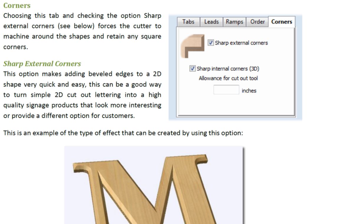
While reading the help section, I discover a large set of features such as the ability to add a bevel which is sharpened at corners. That could come very handy in the future :
I will mill my project next week, time to check the strategy and book a timeslot for the machine.