Attending the Fab Academy in Barcelona, I document each week of intense learning as I come across new digital fabrication techniques.
This documentation is as much a report of what I do as a reflection on why I do so, and will hopefully guide me back to Oceania to spread and make good use of the knowledge gathered along the path.
--- summary of the assignment ---
objective :
Add an output device to a microcontroller board you’ve designed and program it to do something:
what I did :
I fabricated a circuit board designed to control a servo and a Neopixel LED.
download :
Learning outcomes :
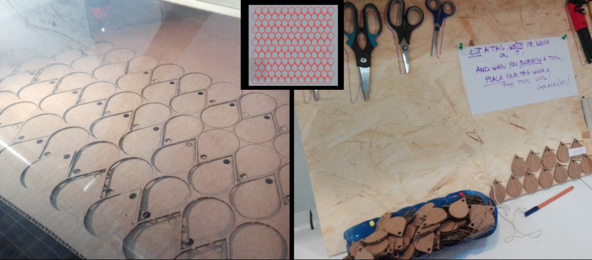
13.04.18 / Awaiting for the RFID kit, I decide to make some tags for the toolboard :
I also book a ticket for the Fabricademy bootcamp during my wildweek card :

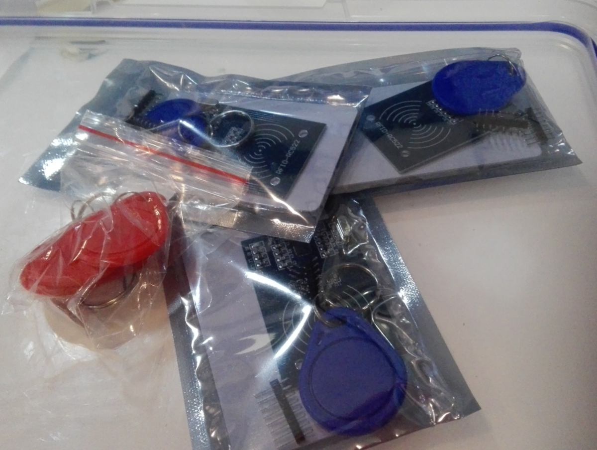
The RFID readers and tags just arrived :
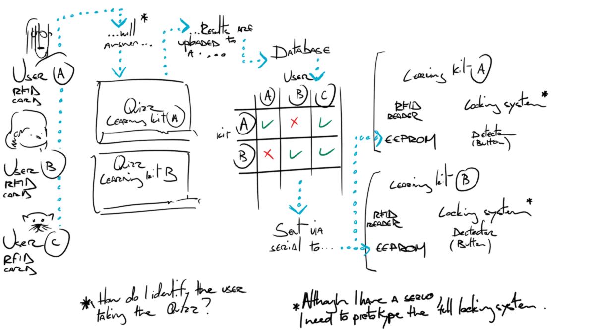
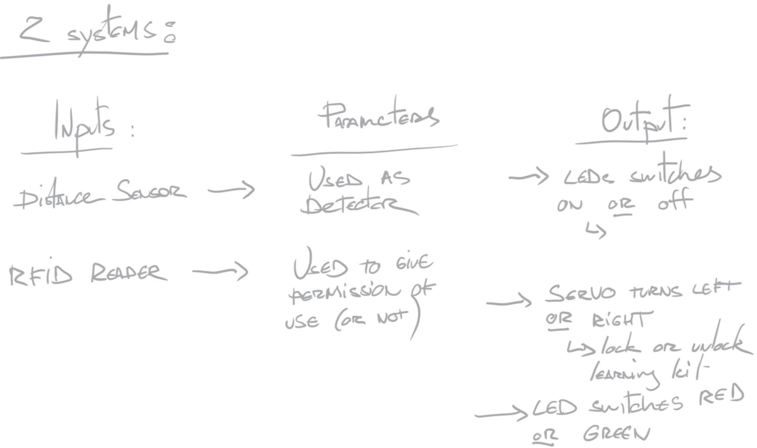
I can now start designing my project for this week :

I then broke it down into small steps and put it in the weekly schedule:
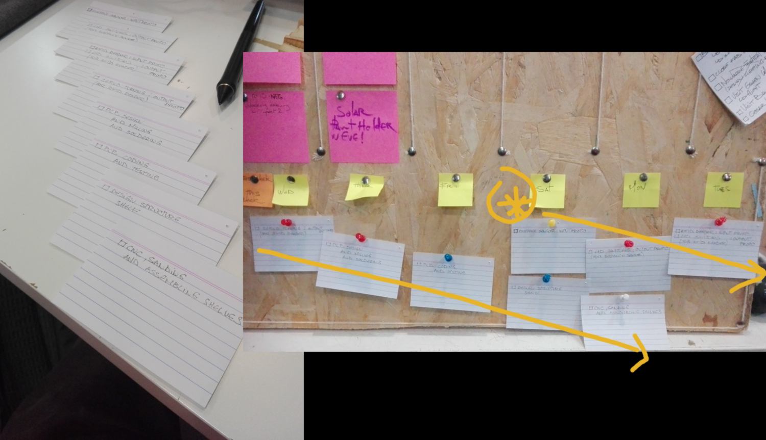
This projection tells me that I will be 4 days late, finishing this project next Monday.
Now, some explanations about my choices : Why do it want to work with a distance sensor rather than a motion sensor? two reasons : first, my shelves are narrow and to access them users must be in from of it, therefore a distance sensor will be able to detect them, even with their rather narrow "vision" fields. Secondly, distance sensors are a fourth of the price of motion sensors.
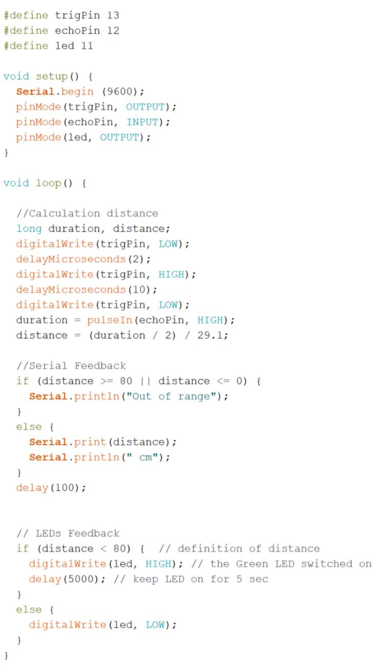
I get started with the distance sensor, reading a tutorial and having a quick look at a technical description. This sensor is actually both an input and output device, sending ultrasound at 40 000 Hz and receiving echos. Knowing the speed of sound and the lag between output and input, it is possible to know the distance between an object and the sensor.
I download some code found on the tutorial page and modify it. The code now calls one LED only. I also adjust the distance at which this LED will switch on :
// LEDs Feedback
if (distance < 80) { // definition of the distance
digitalWrite(led, HIGH); // the Green LED switches on
I add a delay so once switched on, the LED stays on for 5 seconds :
delay(5000); // keep LED on for 5 sec
}
else {
digitalWrite(led, LOW); // LED is off otherwise
}
The sensor works well although the serial Feedback has a delay which slows down the detection process. Once taken off (I won't need it for the final design) the detection will be faster.
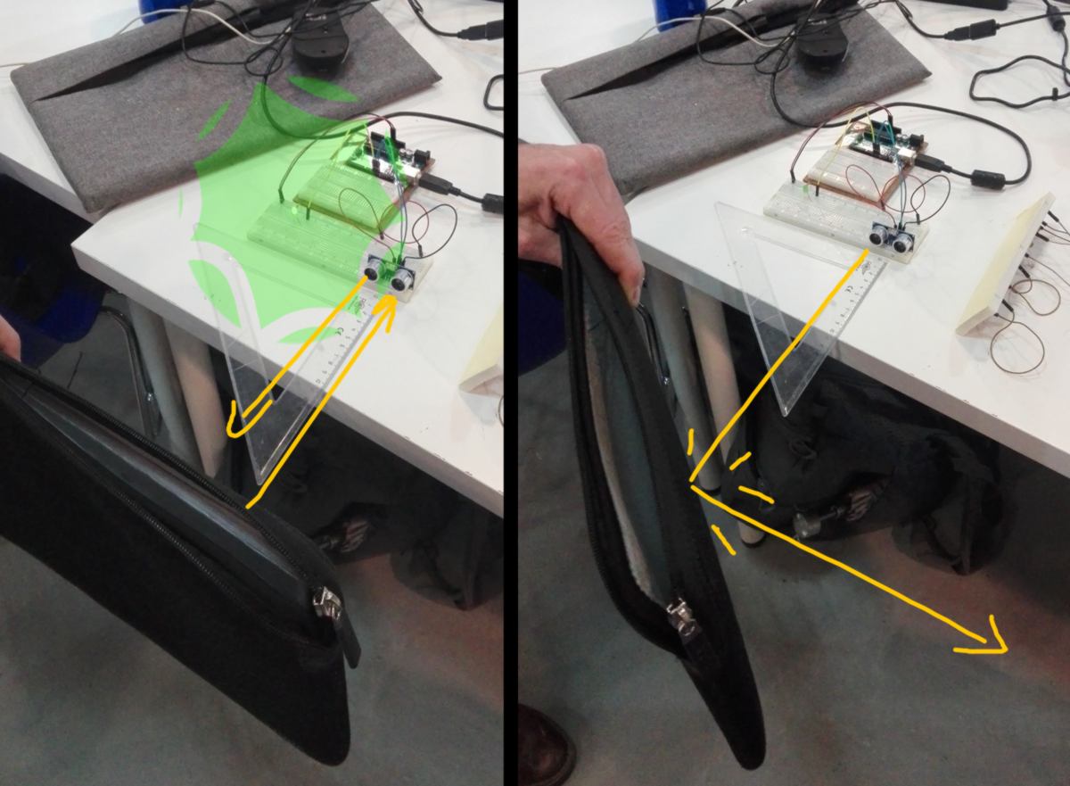
One drawback of this sensor is that, for the ultrasound to bounce back and trigger the LED, it needs a flat surface. If the surface of the object in front of the sensor is angled, the ultrasound does not bounce back, is not returned and therefore the LED does not switch on :
The input is functionnal enough. Now the output - the sets of LEDS - must be an invitation for the user to swipe its RFID card, pointing at the RFID reader. This involves motion between least 3 LEDs - to provide a sense of direction when stiching them on and off. This is when Charliplexing comes handy. I did not understand it until I bumped into this explanation on another student's computer :

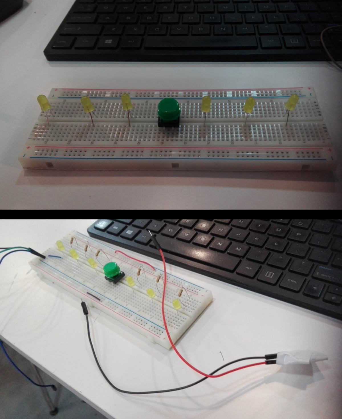
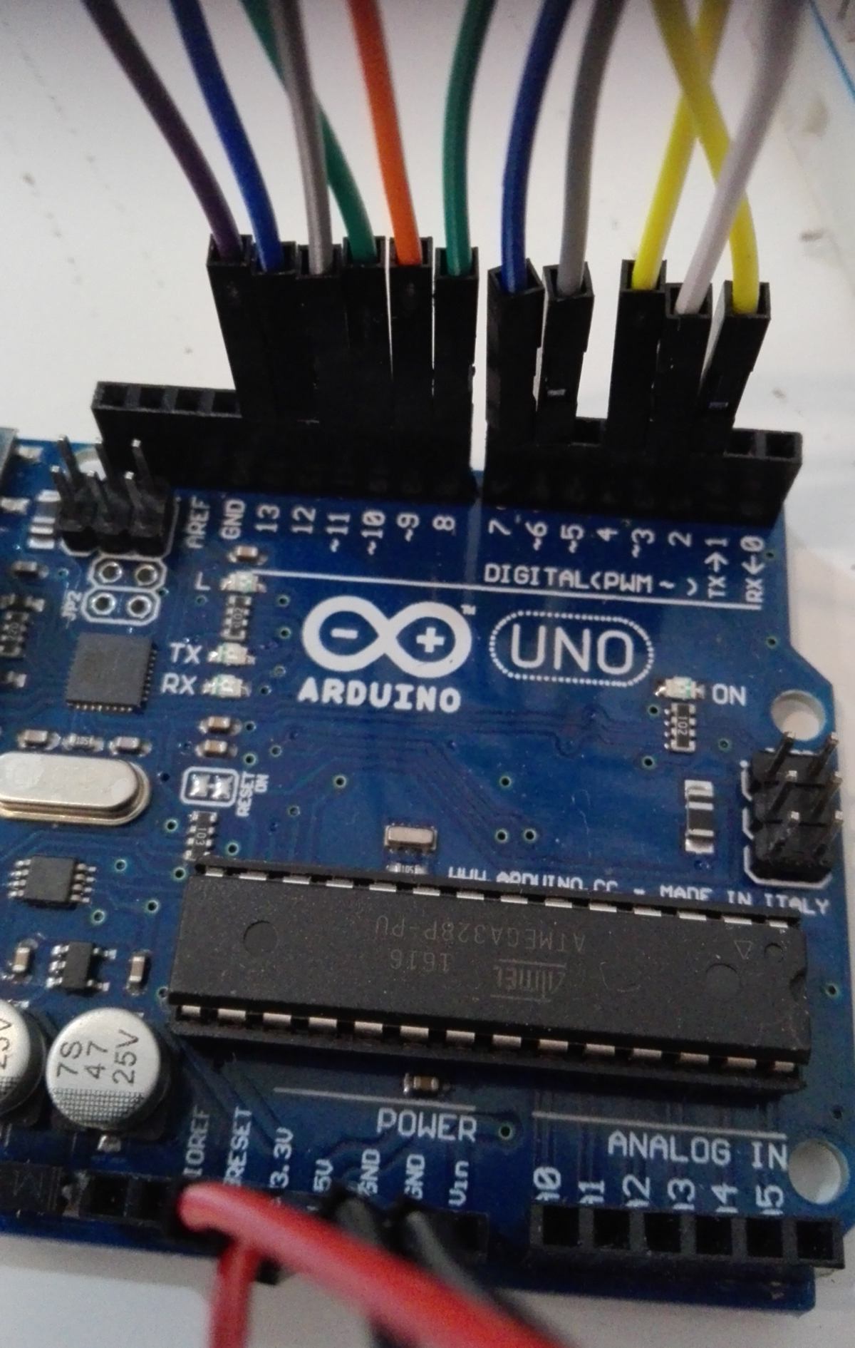
I set up 6 LEDs on another breadboard, the way I wish them to visually surround the RFID reader (represented by the green button there). I test each of them individually with a 3V battery and add a red and a black wire as a reminder of the directions of the LEDs :
I then set up the connections between them following the chart above :
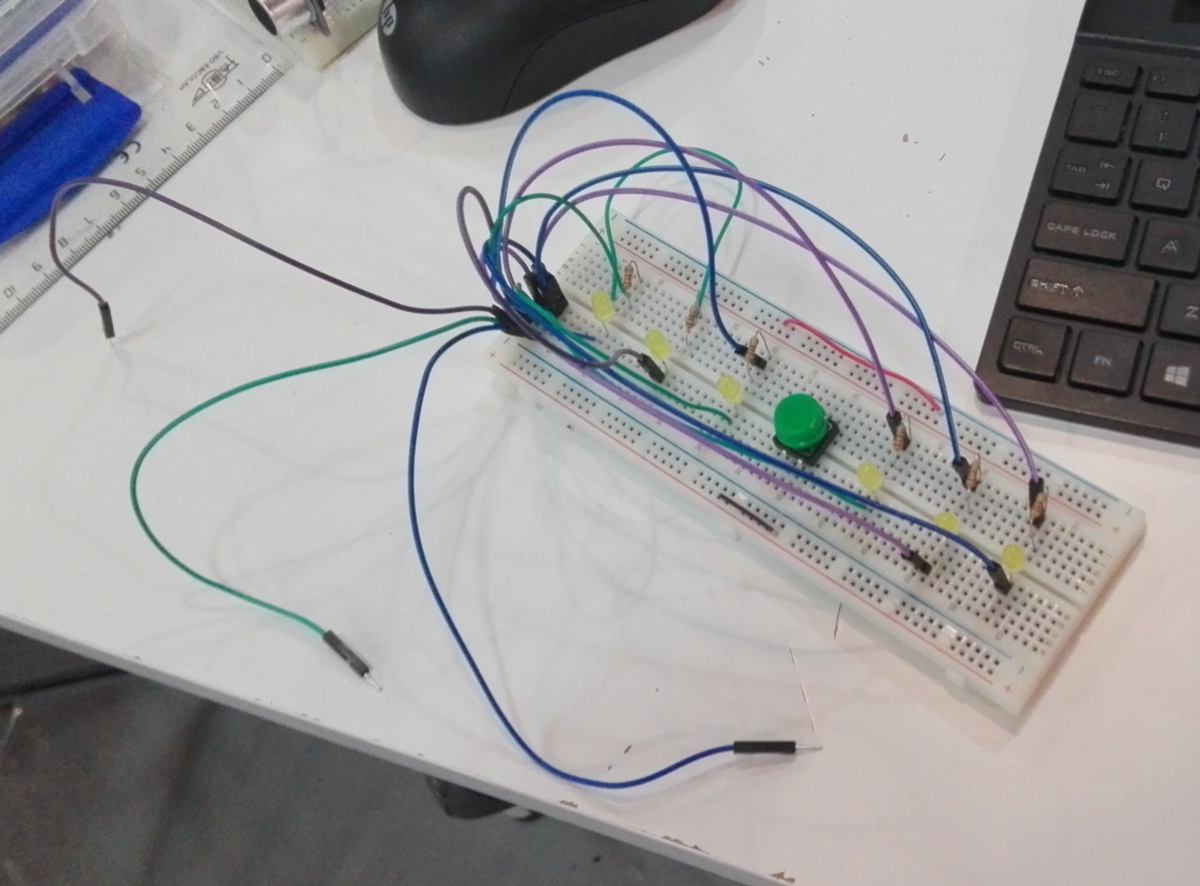
The wiring is becoming complex. On a PCB this setup can look cleaner, but once the LEDs are further away, it gets really intricated. What if I decide to add more LEDs afterwards? I start looking at other systems, such as LED stripes and Neo-pixels. I saw the latters on Joris Hello board. How do they work?
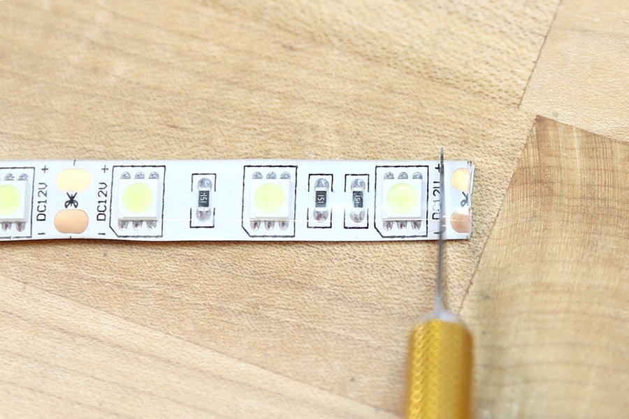
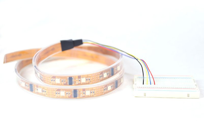
I find some basic infos about LED stripes on Instructables. I learn that what I am after are individually adressable, digital strips or LEDs. They can be cut and soldered, and more importantly the wiring is straightforward :
A visit to the nearby electronic shop is due tomorrow.
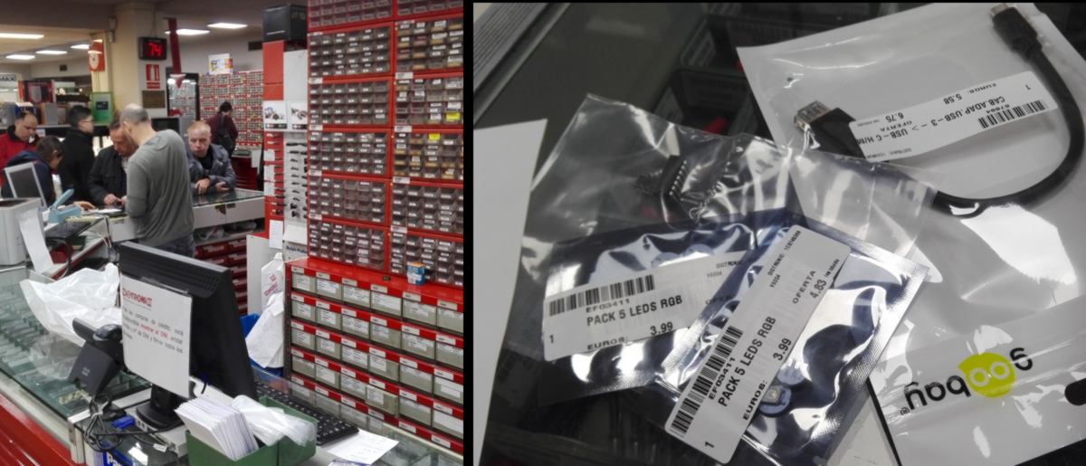
15.04.18 /I find a teeny tiny Huaqiangbei here in Barcelona and apart from the cost, it feels quite similar, all transaction handled by hand.
I find it curious (as well as inefficient) that customers still need to take a paper ticket and wait a mere 15/20 min to be served when other automated systems such as automatic check-in counters have been developped by companies that aren't specialised in electronics, here Air New Zealand :

On a side-note, these companies still employ check-in staff, they simply are more adaptable and personable, freed from their tedious computer-duty.
Since I do not have a soldering iron at home, I will await tomorrow to set up the LED system. I begin to set up the RFID reader. I follow a tutorial to put together a simple setup after downloading the library :
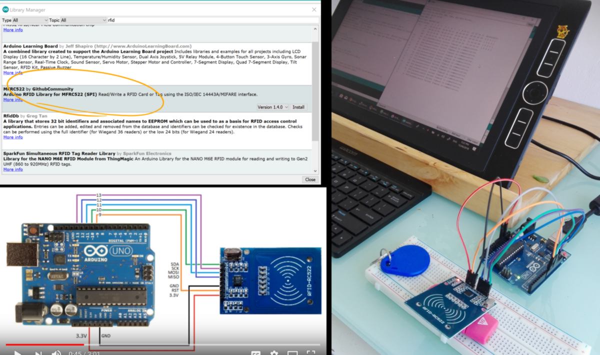
The RFID reader works. Now I look for something that recognises cards and allow access to them :
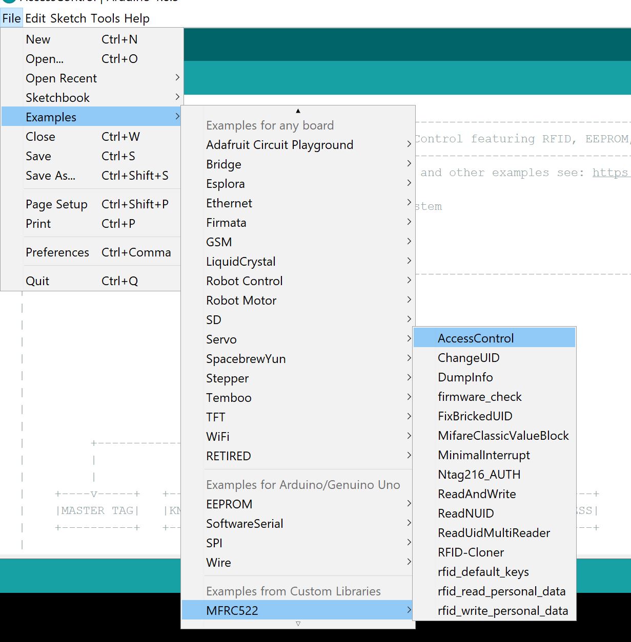
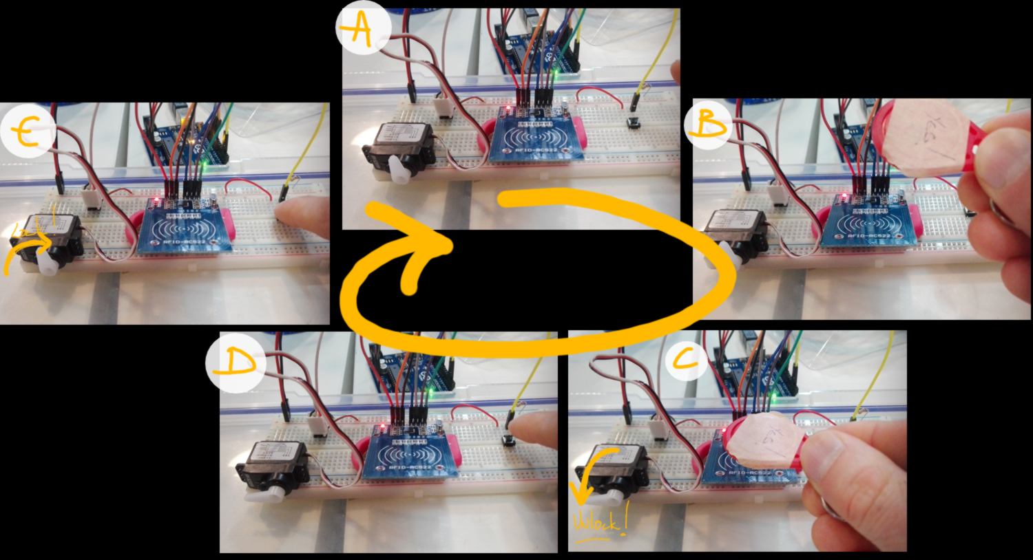
This system uses a Master tag to authorise new tag to get access, following the steps below :
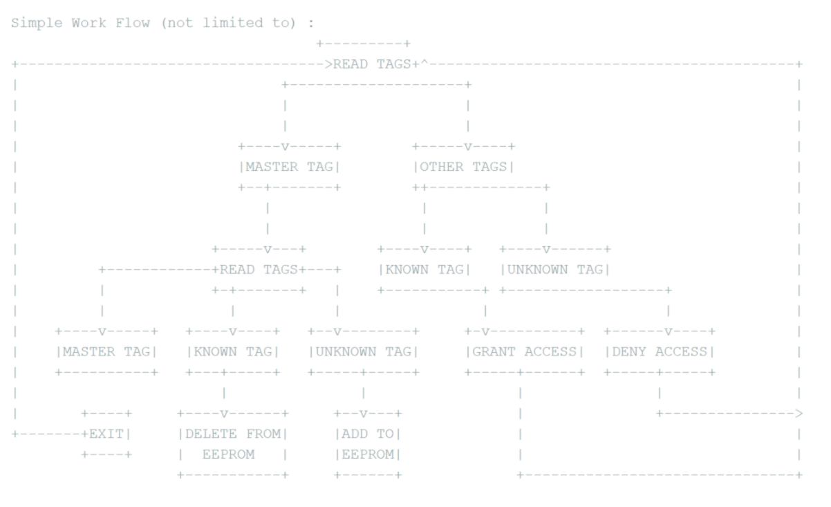
The system works well. It stores information on non volatile Arduino's EEPROM memory to preserve Users' tag and Master Card. No Information is lost if power lost. As a side note, EEPROM has unlimited Read cycle but roughly 100,000 limited Write cycle.
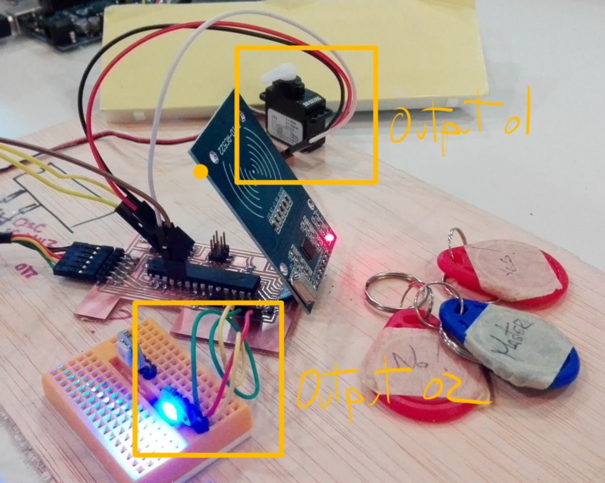
The locking mechanism also requires a servo and a button. The servo will lock and unlock the learning kit. It will be controlled by both the RFID reader (to unlock the kit) and a button underneath the kit. When the kit is stored on its shelf, it pushes on the button, which tells the servo to lock the kit.
For this part I will refer to the Arduino Projects Book and write some code myself, mixing up different projects : "the mood cue" and the "spaceship interface". I also use the language reference and an example online.
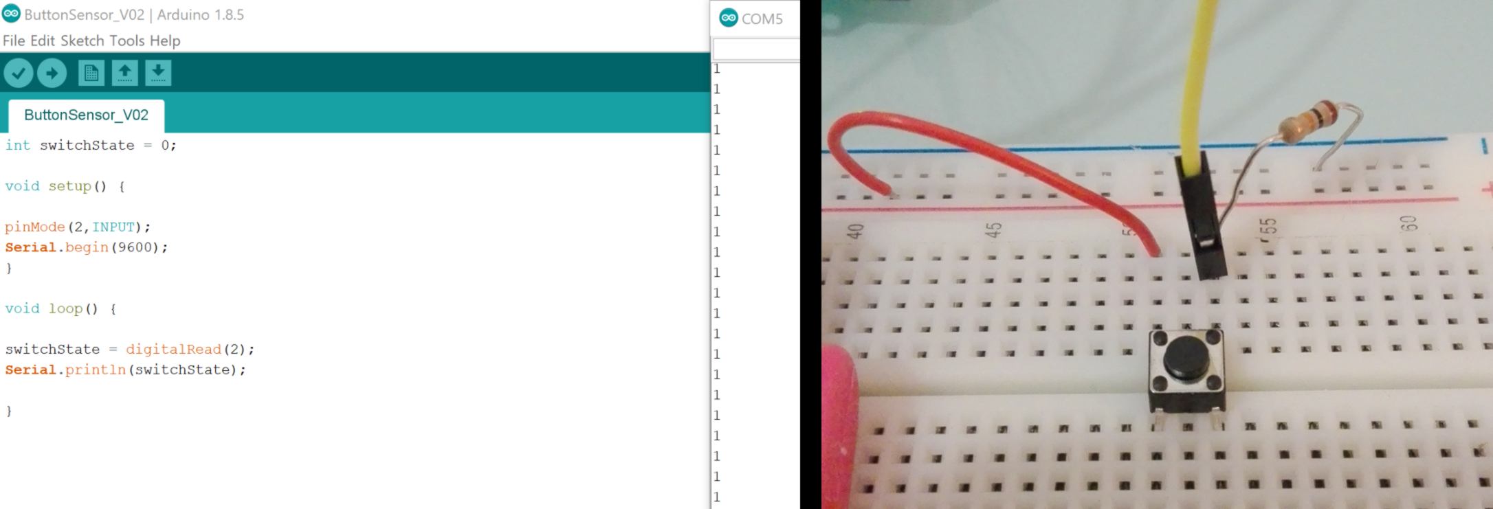
First I check that the switch operates properly :
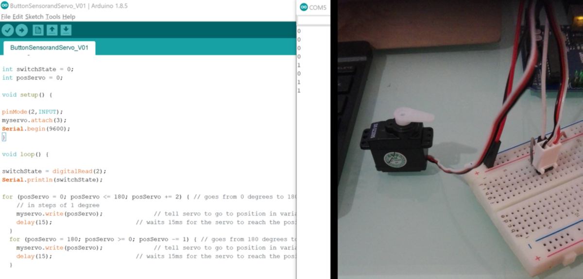
Then I add and check the servo :
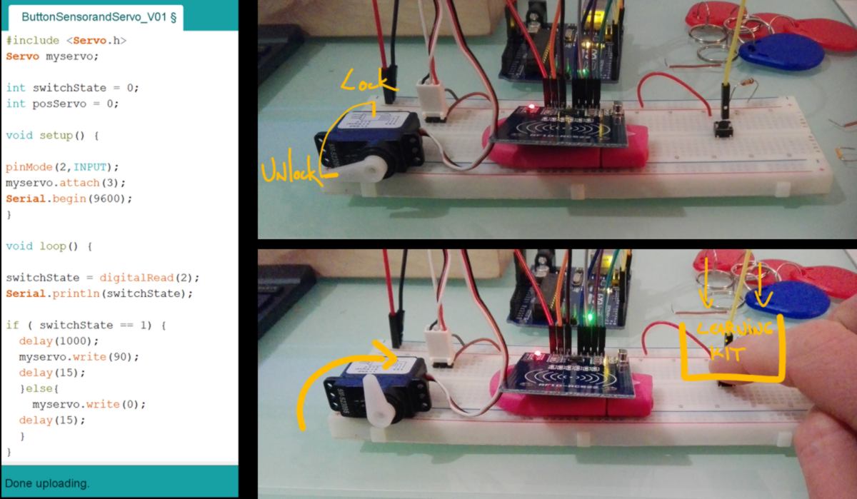
Finally I use the button as an input for the servo : When the button is pressed, the servo waits for one second, then spin 90 degrees, theoretically locking the learning kit into position :
16.04.18 /Today I connect the RFID reader to the servo to unlock the learning kit. To do so I must merge the code for RFID access control and the code for the the sensor and button.
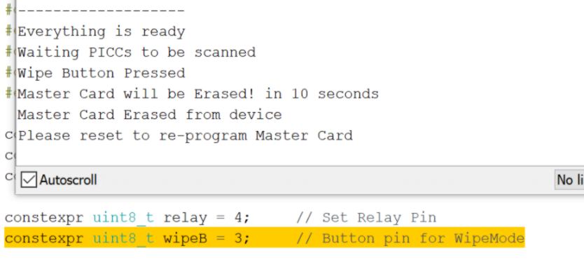
Firstly I need to better understand the code for the RFID access control. Firstly I re-assign the "wipe" pin to another pin. By default it was using the pin (3), defined for the button detecting the learning kit:
I also see that the code is designed to open a door, so there is a pin set up defined to be connected to a relay. There are also 3 pins defined to be connected to LEDs for visual feedback. I will use these later when adding the addressable LEDs.
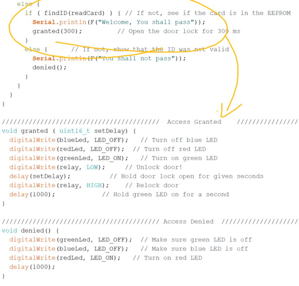
I find the part that I need to tweak to trigger the servo :
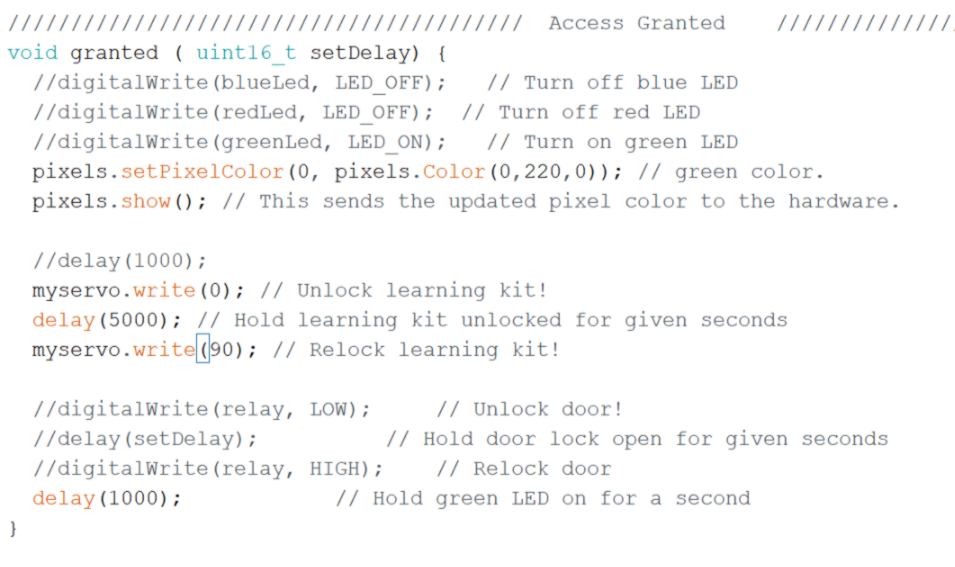
I am going to modify the "granted" function so as to unlock the learning kit when the function is called. I add the Servo library, define the Servo Pin and tweak the "granted" function :
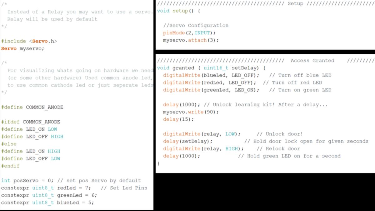
I modify the value of the position of the servo to make it align with its body, physically giving space for something to be taken away.
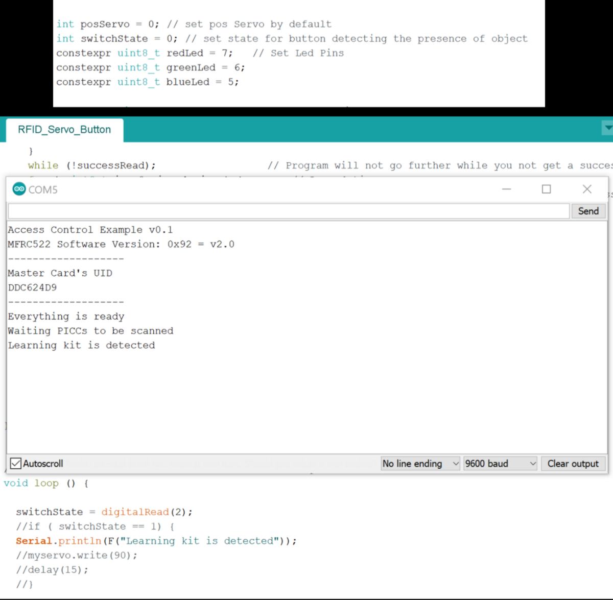
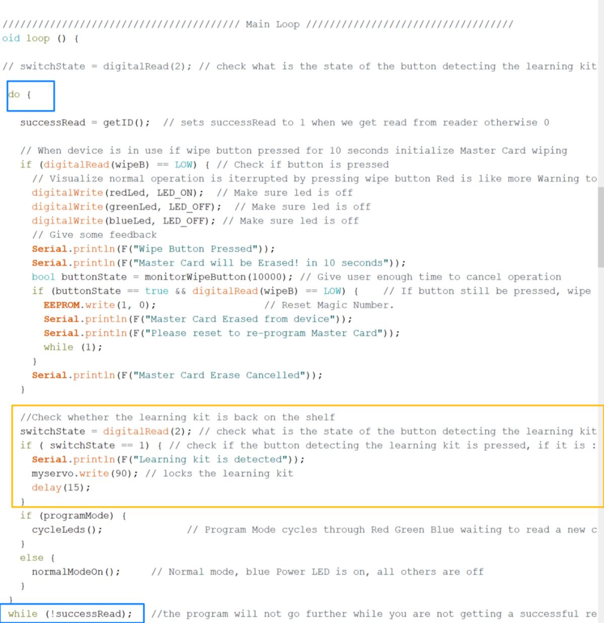
I now add the button, so that the learning kit gets locked if it is detected for 2 seconds on its base. I have already defined the PIN, I simply add the function switchState. This time I modify the void Loop.
In this situation, the Serial.println(F("Learning kit is detected")); command should repeatedly prints in the serial. However it does not, meaning there is something in the code that stops the loop from looping.
I learn about how Do...While structure controls the flow, here refraining the rest of the code to be read and repeated.
Looking at a way to break this inner loop, I find the "brake" statement :
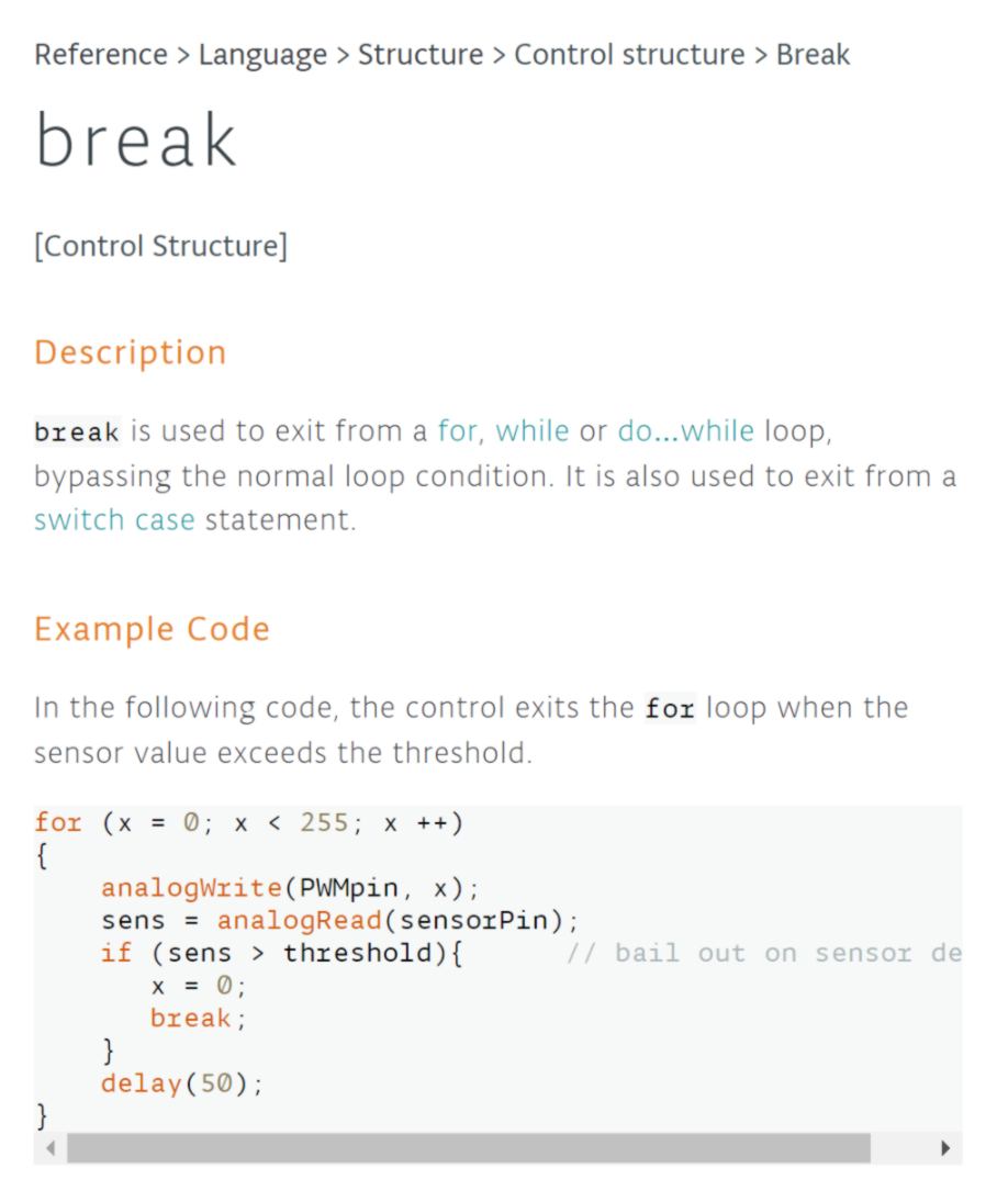
Before diving into this, I test the DO/while function and realise what is inside this function (Between Do and While) is continuously looping. Therefore by adding my if statement there it will be continuously checked. I set it up and test it out :
I make an adjustment, adding a delay ( delay(3000);) after the mechanism is unlocked to give enough time for the user to pick it up before it locks itself again ( if the Learning Kit stays on the shelf, it keeps on triggering the button which eventually locks the mechanism).
The Locking/Unlocking system is now functionnal!
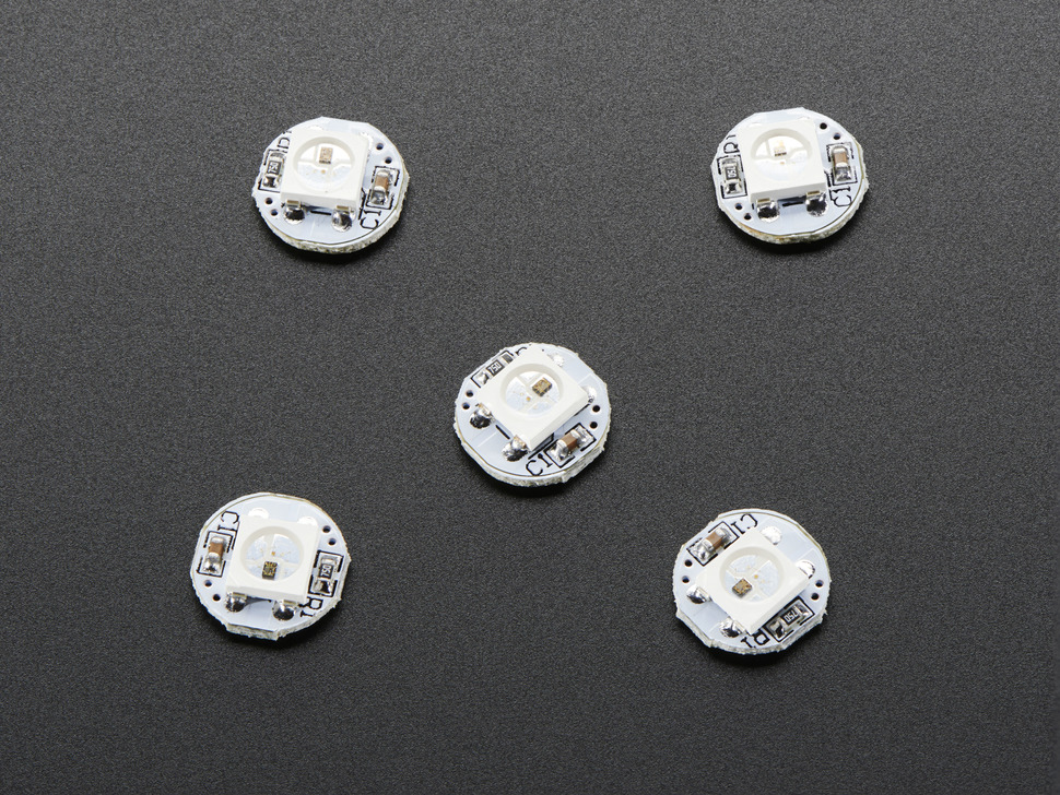
I now move on to the RGB LED system. I am having a really hard time finding resources for the LEDs I bought over the weekend. I post a message directly on the webstore of Elecfreaks :
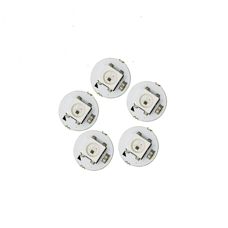
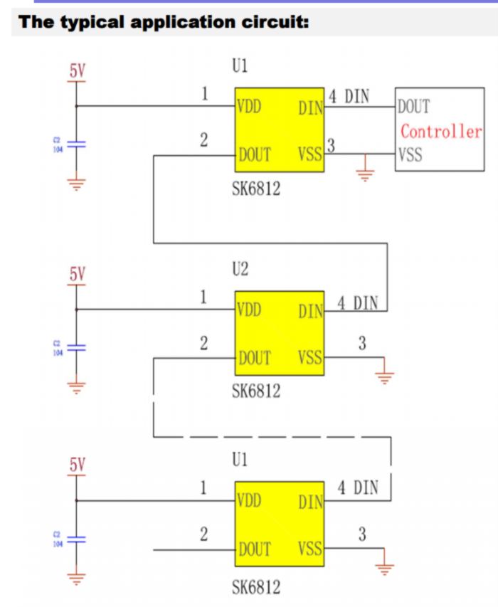
Their tutorial page does not have any info about it. I am going to guess that each Single pixel dot is based on SK6812 core, which has integrated control circuits and RGB beads - datasheet here. They can be coded the exact similar way as Adafruit neo-pixels.
Some very specific recomendations are given on the adafruit website about power supply. The bottom line for me is :
Can NeoPixels be powered directly from the Arduino’s 5V pin?
Sometimes. The Arduino can continuously supply only about 500 milliamps to the 5V pin. Each NeoPixel can draw up to 60 milliamps at full brightness. So yes, you can skip the separate DC supply and power directly off the Arduino as long as just a few pixels are used, more if the colors and overall brightness are low. When in doubt, give the pixels a separate power supply.
I install the adafruit-neopixel library. Examples become available :
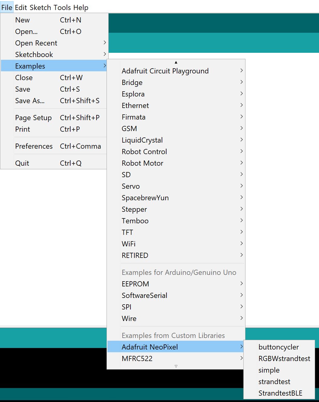
I will follow the "simple" example to test out my LEDs.
about the layout, I will set up 9 LEDs around the object supporting them (I have not decided whether to use the support of the Learning kit or the learning kit itself) :
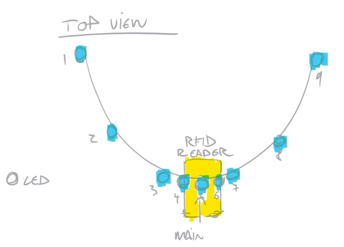
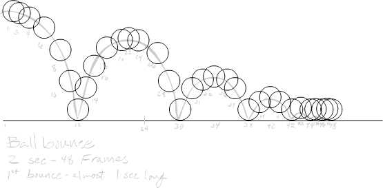
LEDs are spaced out so that when lit up consecutively with a regular delay, it will provide a slow-down effect leading the eye of the user to the RFID reader location. This is a basic rule for animation, as demonstrated by the break down of this animation of a bouncing ball:
Using only 9 LEDs means that in case I use all of them at full power, I will only attempt to draw 540 milliamps. The arduino supplies a maximum of 500 Milliamps so I will be able to run almost all of them at once at full brightness if I wish so.
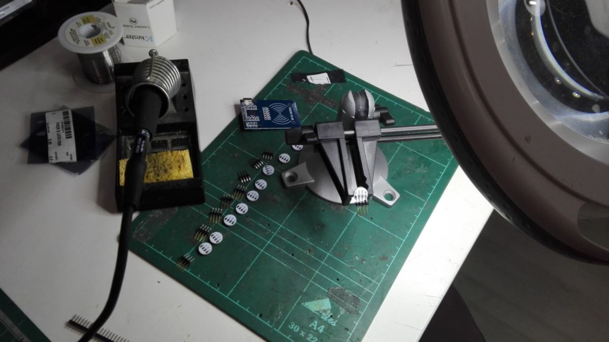
17.04.18 / I prepare the addressable LEDs for a test, soldering them to pins so they fit on a breadboard. I connect them as if it was a stripe, tweak the code and test it out :
Now I will use the LED 1 to provide feedback on the state of the RFID reader. The RFID code was written in order to use three LEDs for feedback. I wish to reuse this setup.
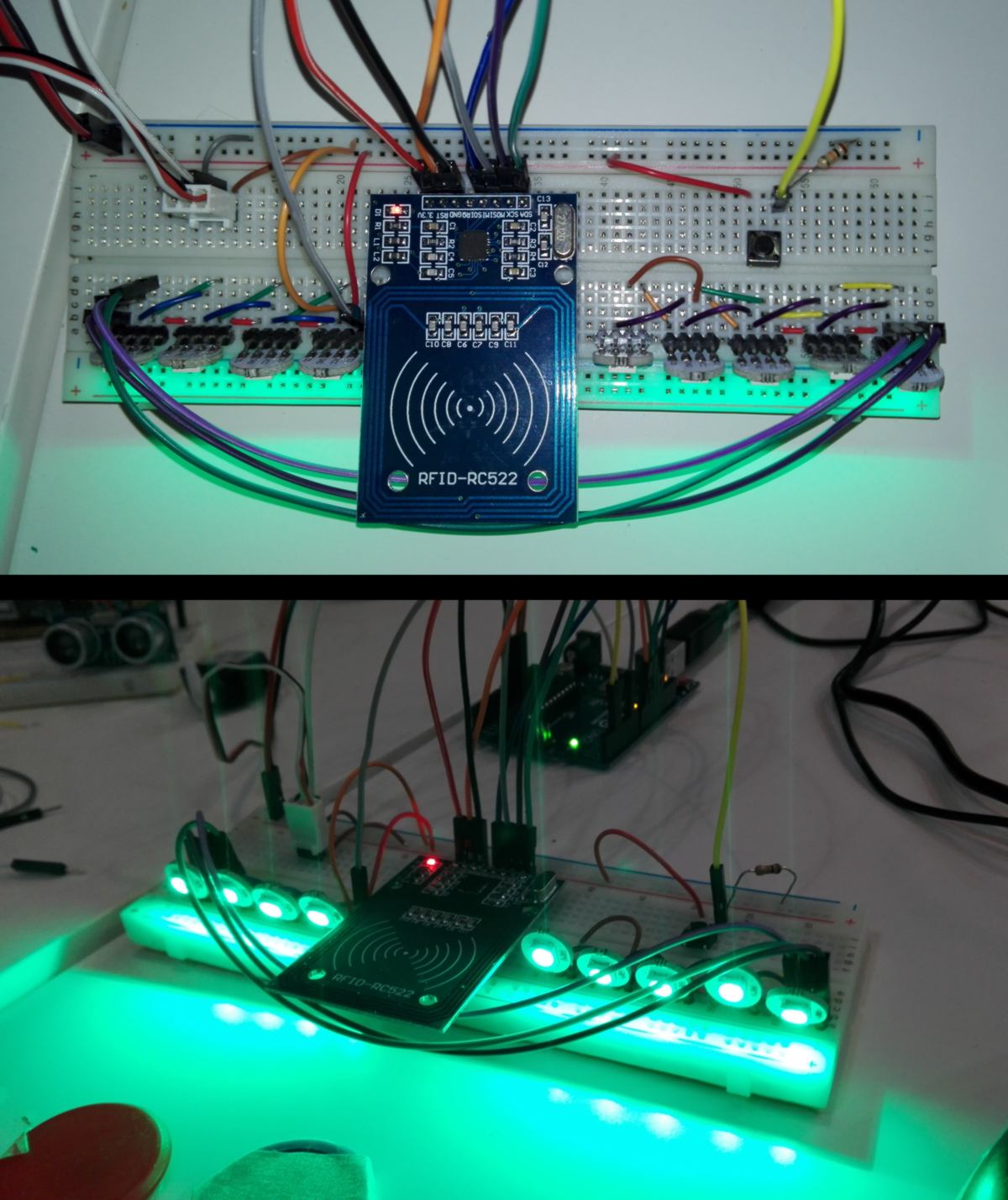
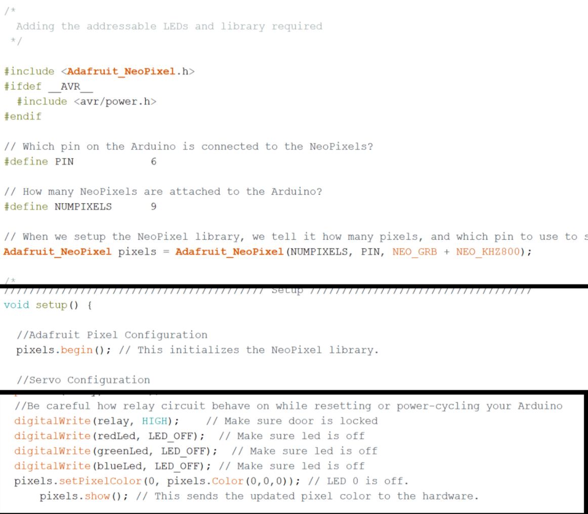
I do a quick test to understand how to switch on one LED only, then implement it in the main code, adding the adafruit Neopixel library and defining the stripe :
I will go through the whole code, and everytime the code mentions a red, green or blue LED, I will swap it with a code for the addressable LED. I use an online table to find color codes.
The light feedback system works well.
I make a few adjustments:
I actually forgot to check whether the Learning Kit was still on the shelf. Is the button pressed or not? I add an if statement :
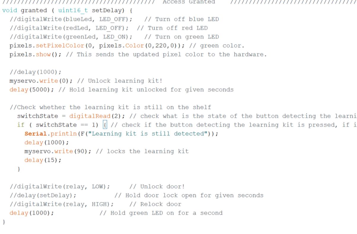
This time it works well.
I make another adjustment. I want the led to switch off after 5 seconds, if nothing happens. I tweak the "normalModeOn" :
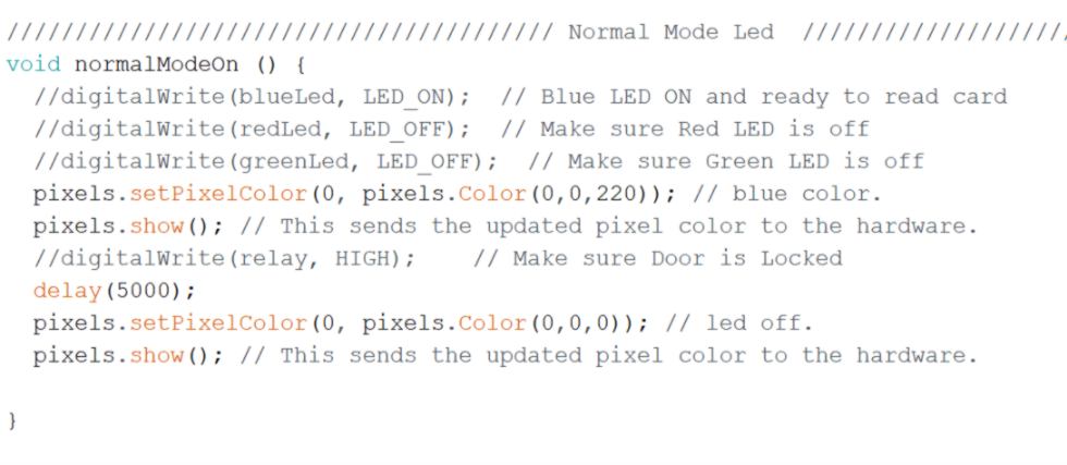
this is a complete failure. Not only the added delay makes the RFID reader slow to respond, since "normalModeOn" keeps looping, the led never switches off. What is required here is a timer/counter perhaps?
Remembering the digital hourglass example in the Arduino examples book, I remember that "The < a href="https://playground.arduino.cc/Code/AvoidDelay"> millis() function helps to solve these problems. It keeps track of the time your Arduino has been running in milliseconds. I refresh my memory by tweaking the example, adapting it to my case :
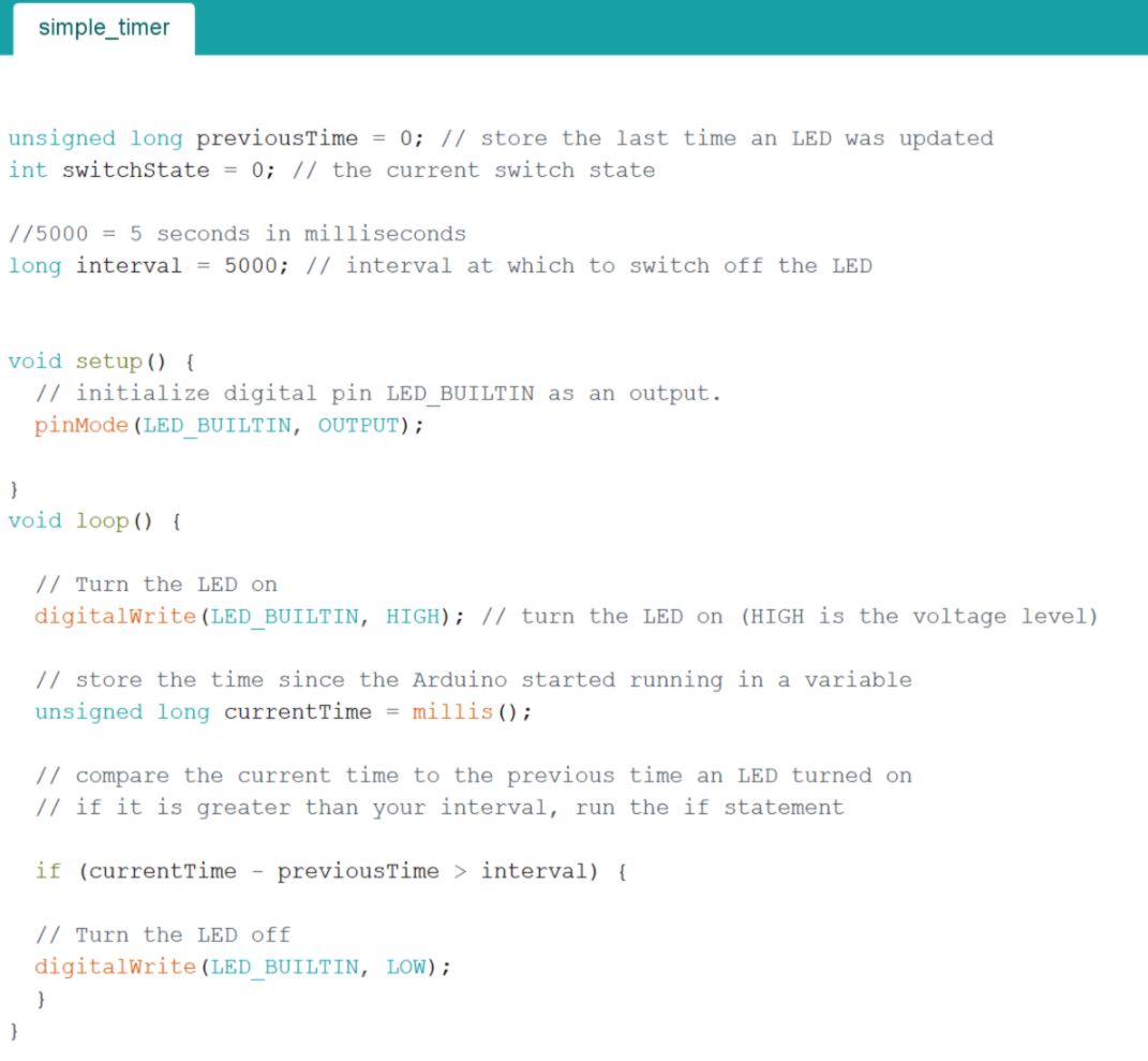
I get to realise that the millis function reads the milllisecond since the Arduino board began, therefore, although I can use it as a reference, I need to set up this reference then use millis to increment it. I tweak my code again.
18.04.18 / Today is one of these days when I get my keys out to enter the subway station. It is promising lateral thinking day.
I go back to the hourglass example and tweak it to make it work with the addressable LED.
I have trouble resetting the timer at the beginning of the loop once only. I try different types of if statements, but since a loops keeps on looping, my variable is reset each time, and the LEDs switches back on. I attempt to set it up as a separate functions outside of the main loops, but realise such functions are only played once and are part of the loop, so it does not solve the problem.
I think that my logic is wrong. The variable that is used as a switch to trigger the LED on must be activated before we enter the function where the LED is switched off, then loop. This way, when the loop keeps on looping, it does not trigger the variable again, and the LED stays off.
I am stuck here, so I am going to move on, and add the Sonar to trigger the extra LEDs. I implement some additional code and when compiling, I get an error :
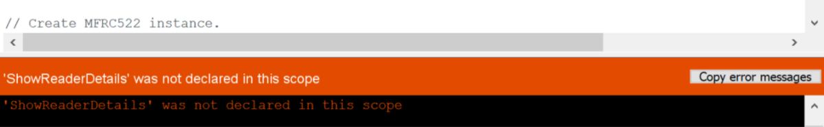
When adding new code in, I put in comment elements that I did not use. One of them was the ability to wipe what was on the EEPROM. That ability seems to be compulsory for the RFID reader to work. So I add it in again, assigning it to another pin and teaking the code so that it does trigger a wipe when the pin is HIGH (not LOW as initially assigned).
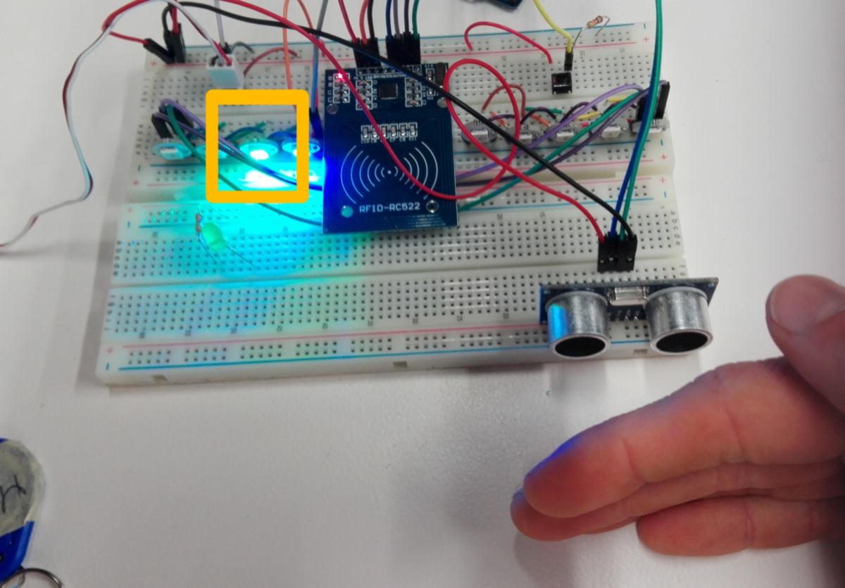
The sonar triggers the second LED ON AND OFF :
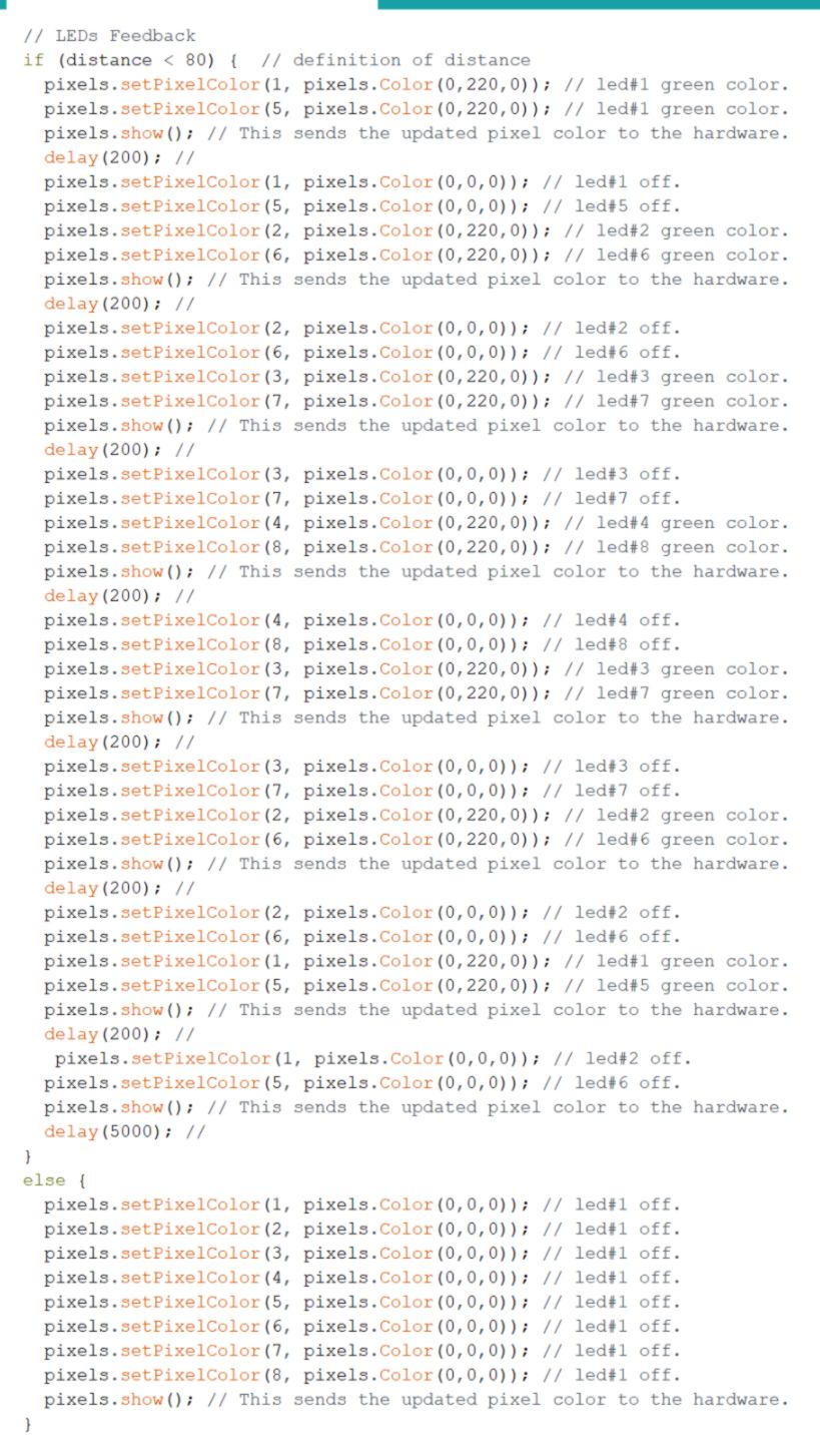
I write an animation for these LEDs :
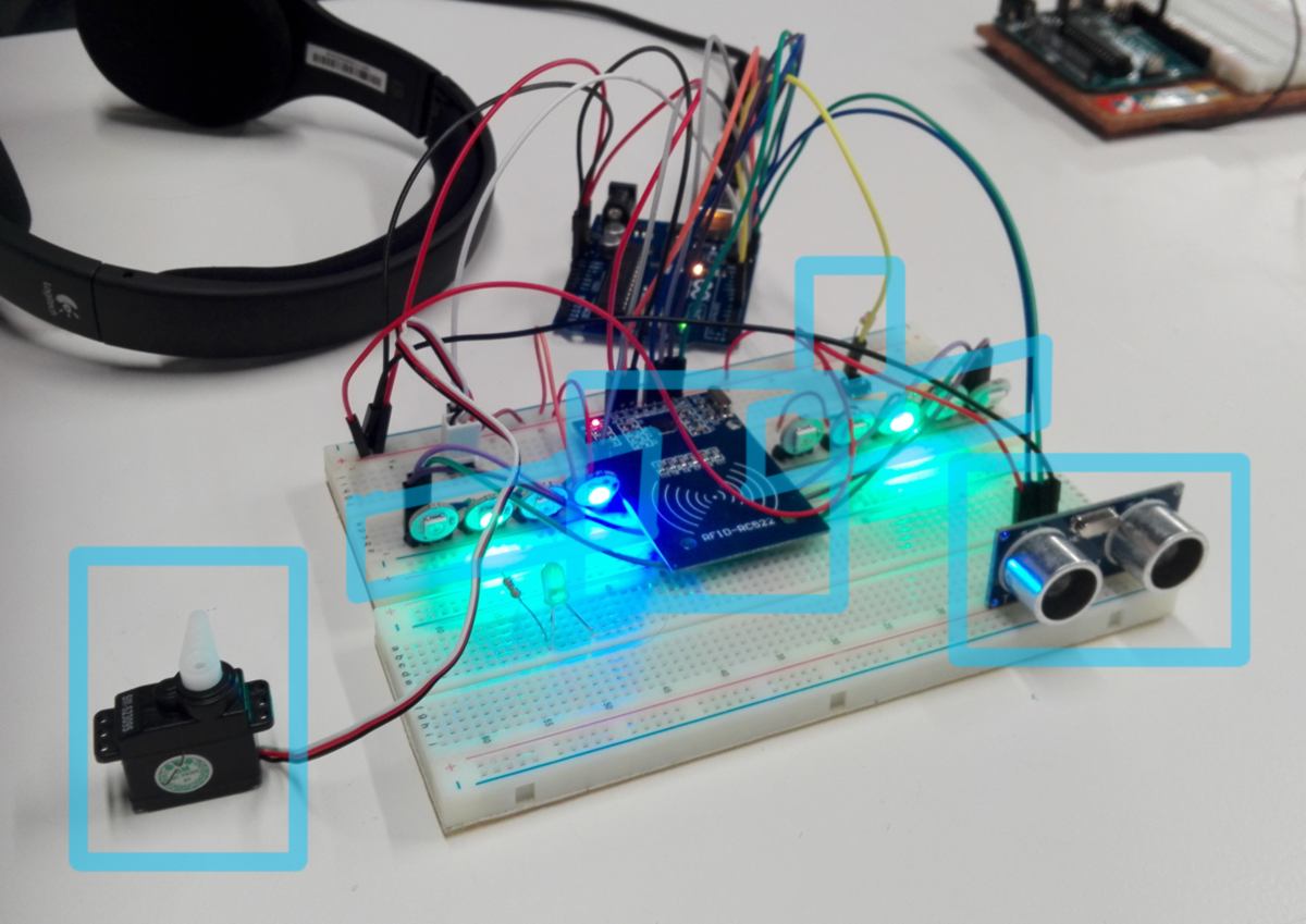
Although the code is now a WIP, I finally have all hardware components put together. I can now move on and design a pcb for these components :
19.04.18 /Before designing the board , I add and test a button and adjust the code to potentially wipe the data off the EEPROM. I make all the changes necessary to make it work :
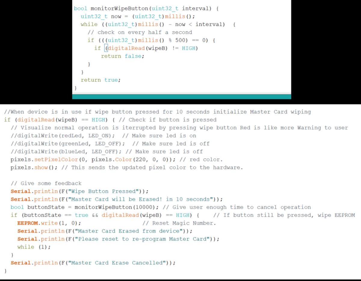
More importantly, what I have found is actually a timer, very similar to the one I wanted to set up for the main LED! I keep in mind that I have a working example to copy/tweak for later. Today milling the board is the priority.
First I am going to choose what microcontroller I need according to the number of pin and memory space required.
First I am going to comment all lines that are not required (such as serialread), select an ATtiny 84 as a microcontroller and compile it:
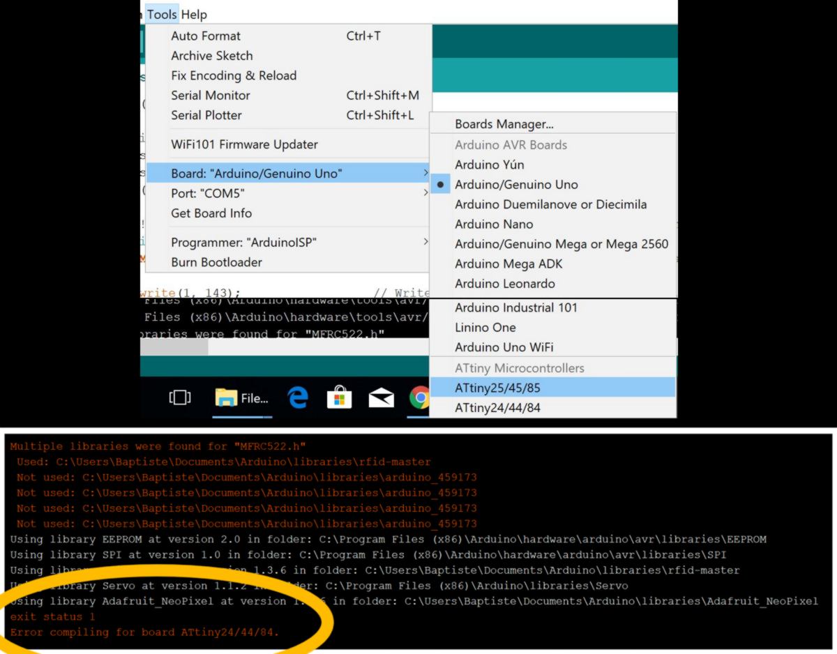
I compile it again using an arduino to check the size of the file :
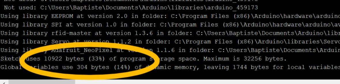
The code is rather large. It won't fit on an ATtiny. I have three other options available :
They all possess three times the memory required for this code. I check the number of pin required by my setup :
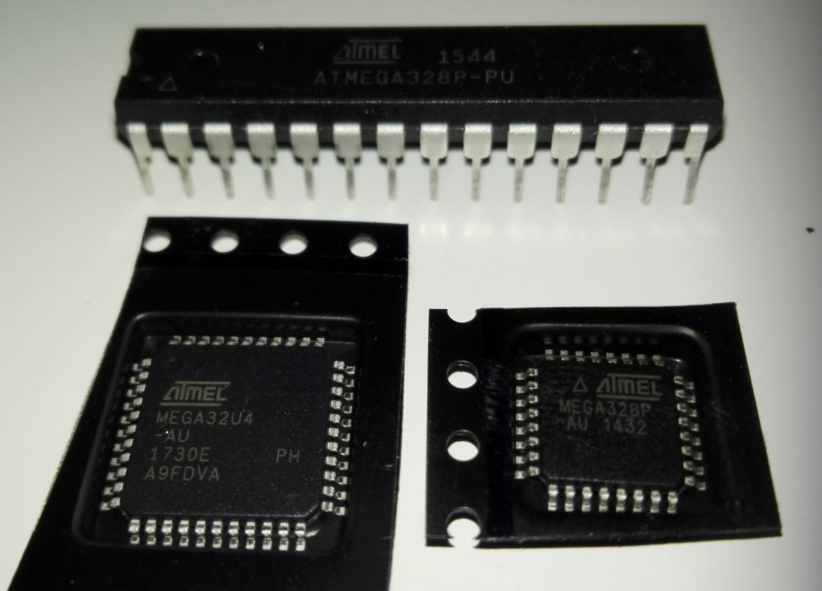
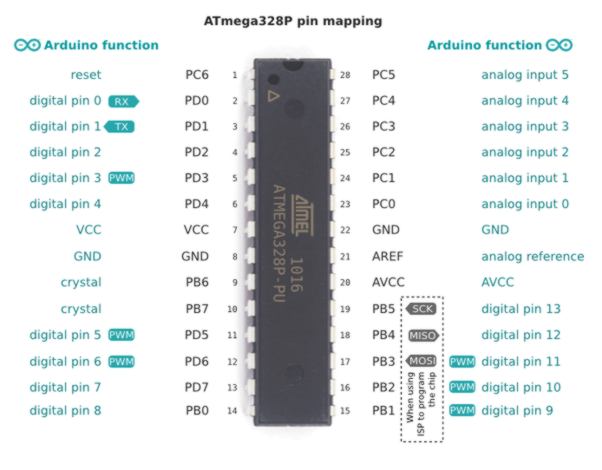
Since the AT MEGA 328P is used on the arduino I know that I fits this requirement. I look at the datasheet for the other chip (used on arduino Leonardo).I read that : The Leonardo differs from all preceding boards in that the ATmega32u4 has built-in USB communication, eliminating the need for a secondary processor. I am not specifically interested in USB communication, therefore I will use a AT MEGA 328P.
I look at the price of each chip on Digi-Key. The au version are cheaper, therefore I will use the au package.
I also need two types of voltage : 3.3V and 5V. I look into how this is setup on an Arduino board set up on a breadboard, a Sparkfun tutorial about voltage divider and the arduino uno schematic :
I learn how the 5V is regulated on the Arduino board and how to modify it to make the whole board run on 3.3V. It is not what I am aiming at but is interesting since it points out at a 3.3V voltage regulator.
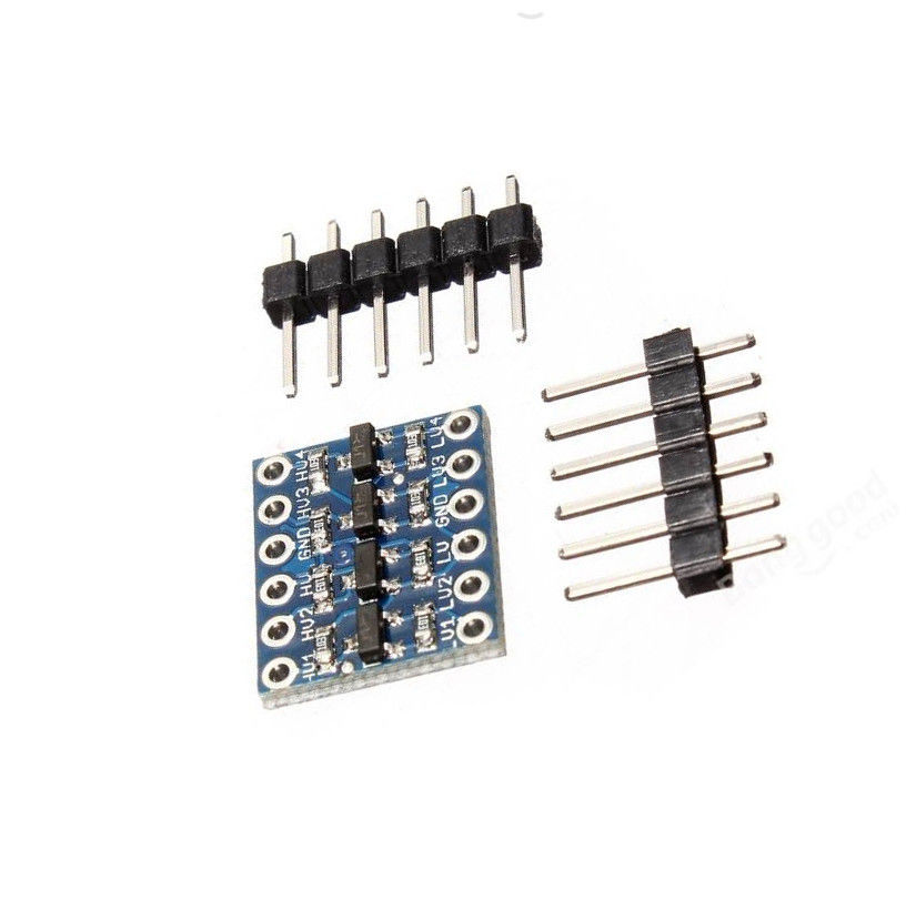
Another tutorial recommends the use of a Logic Level Converter Bi-Directional Module 5V~3.3V.
I also find some useful recommendation to design the PCB using a voltage regulator.
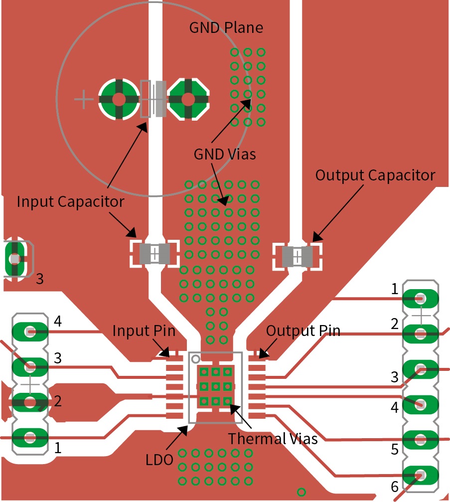
I find a very simple step-down module, proving that it is a relatively simple operation to do :
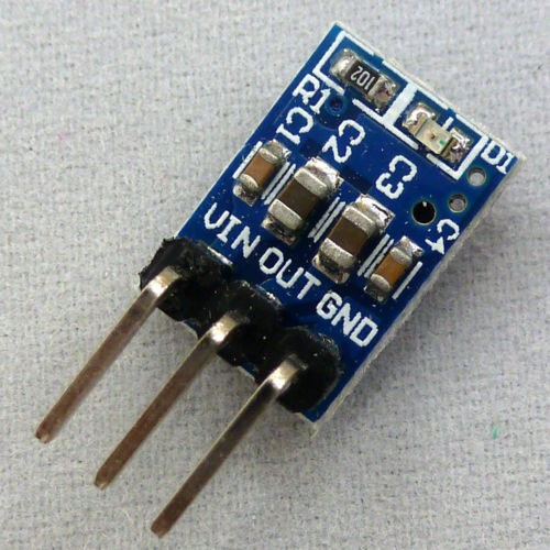
And finally looking at options and asking around, I find what I am after, sitting on a shelf in the elctronic lab :
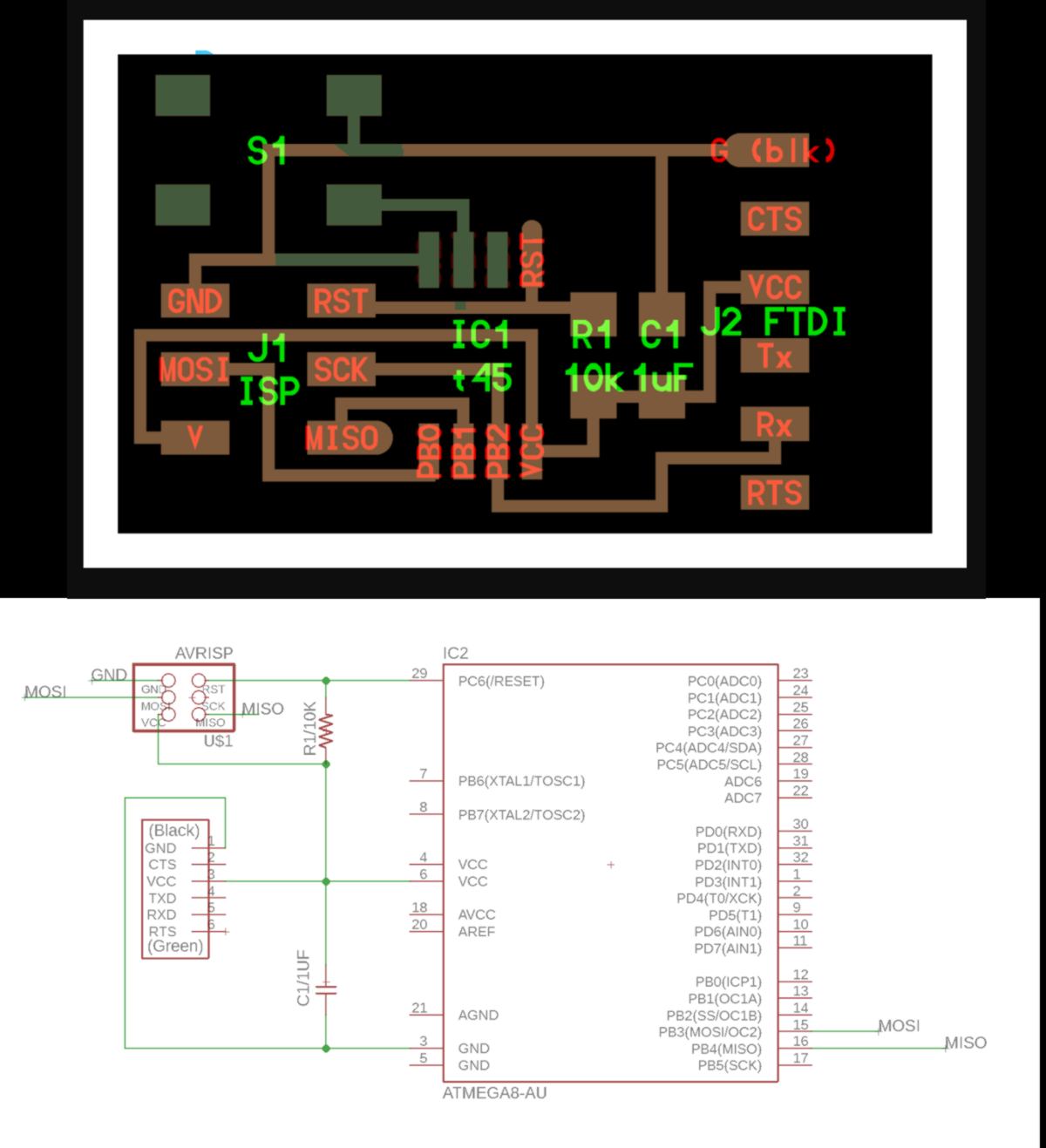
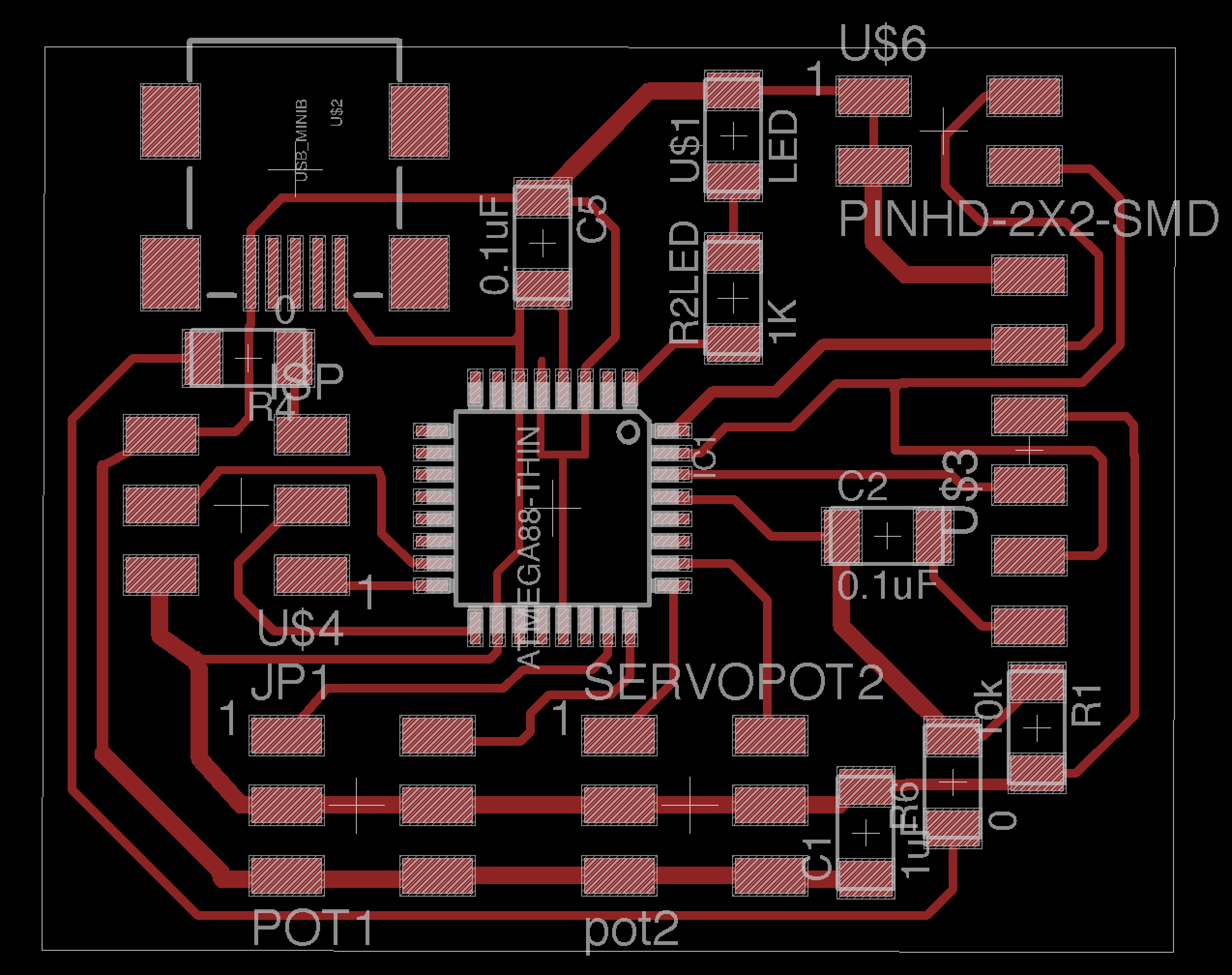
I get started with the schematic :
As usual I copy a board from the fabacademy for the most basic connections :
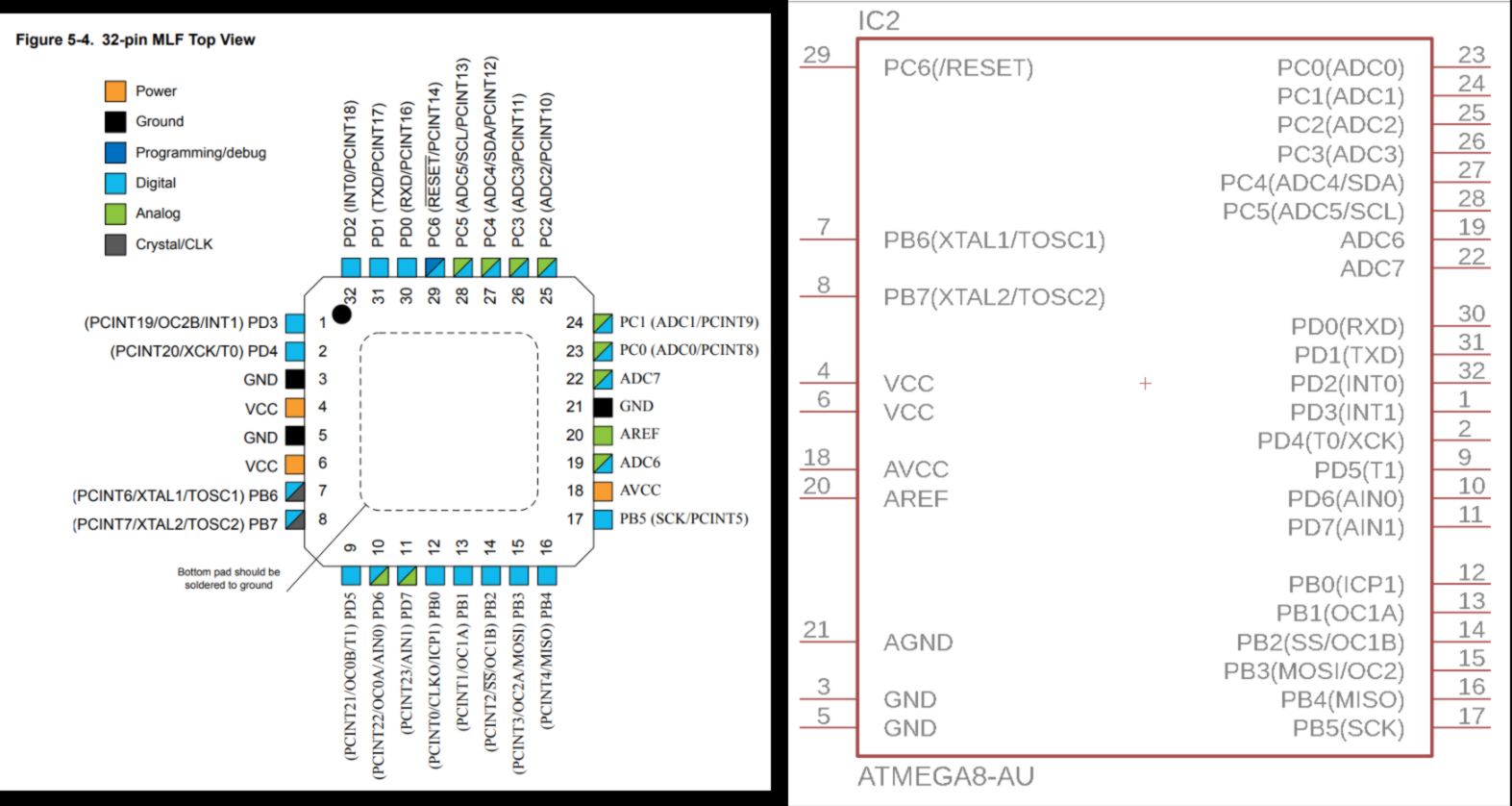
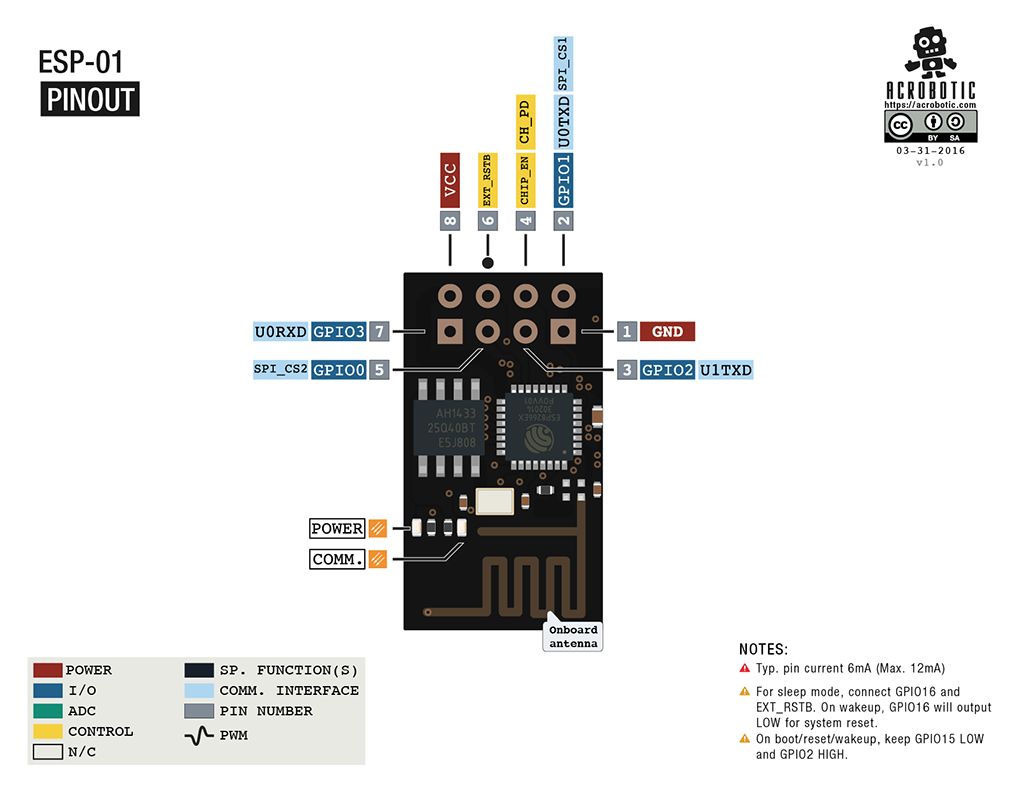
I add extra component using the pin mapping below :
I keep on adding libraries from Adafruit Sparkfun and other random sources to add all elements to my schematic.
As I discuss with Xavi about communication with my PCB in the future, ideally collecting data scanned by the RFID reader, Xavi recommend me to add a wifi module to my board. I find some information on the Fab Academy website of Wim Lanz, a student from last year :
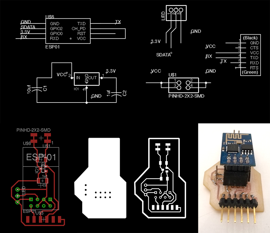
I cannot find such module at the lab today but I have a bluetooth module handy. However I want to get to a final product before adding new elements to my board. I leave aside all communication system with my board, leaving it for next week.
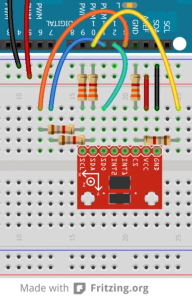
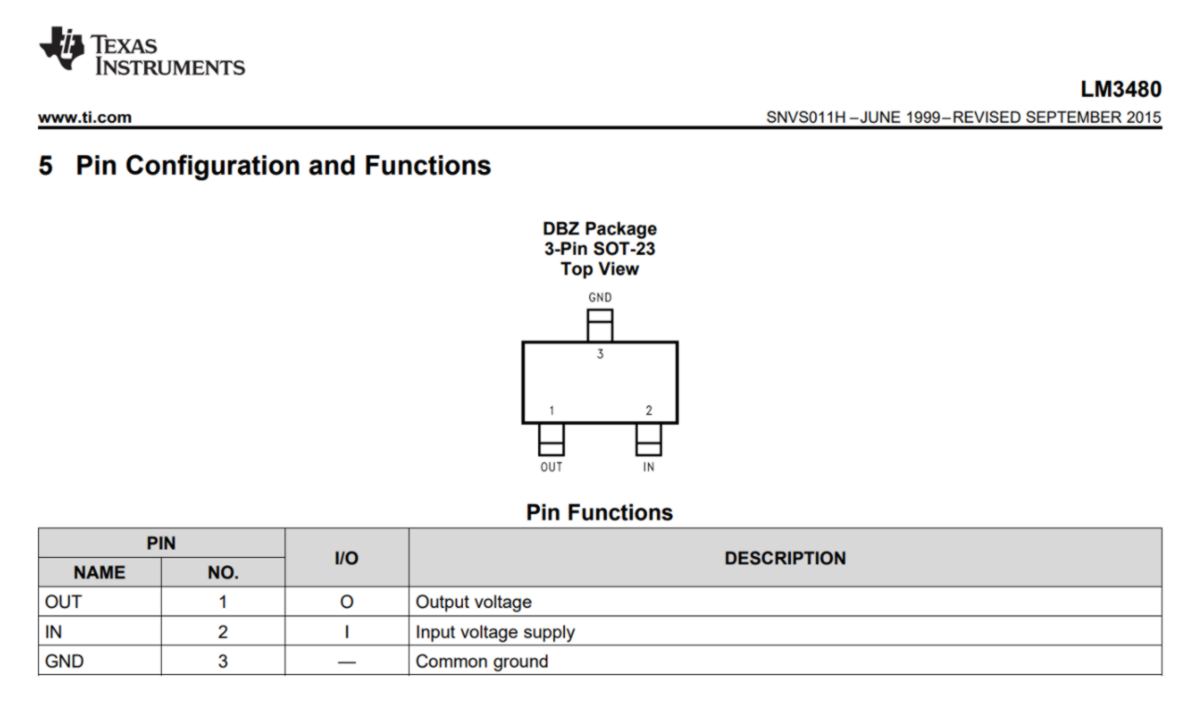
I set up the step down for the RFID reader using its datasheet, finishing the schematic :
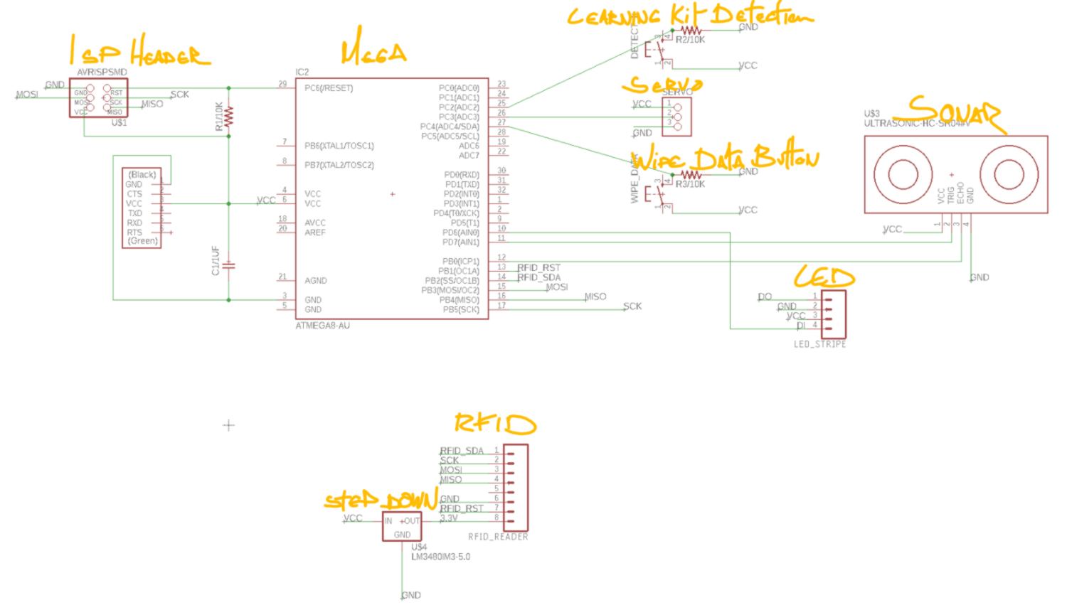
I am going to do a last check, one pin at a time, before moving on to the routing.
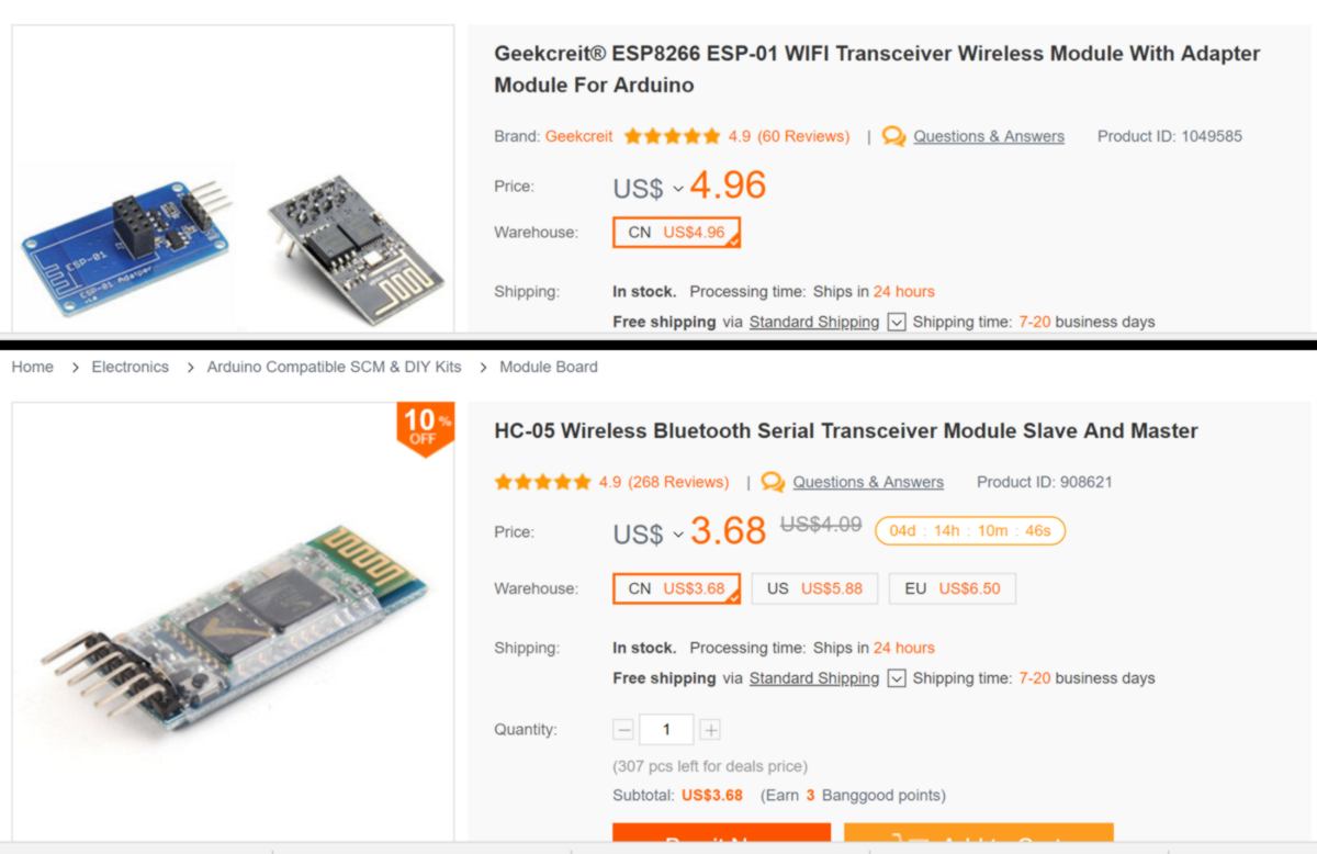
Now I am reassured the current schematic is correct, I start considering communication devices. Wifi, Bluetooth or serial? Since I might end up with many learning kit, it would be better to get rid of extra wiring. No serial then. The price difference between the two last options is not considerable :
Since it is too late to do any milling, I might take some time to look into it before tomorrow. So, what is that thing that I want to achieve with a cloud connection?
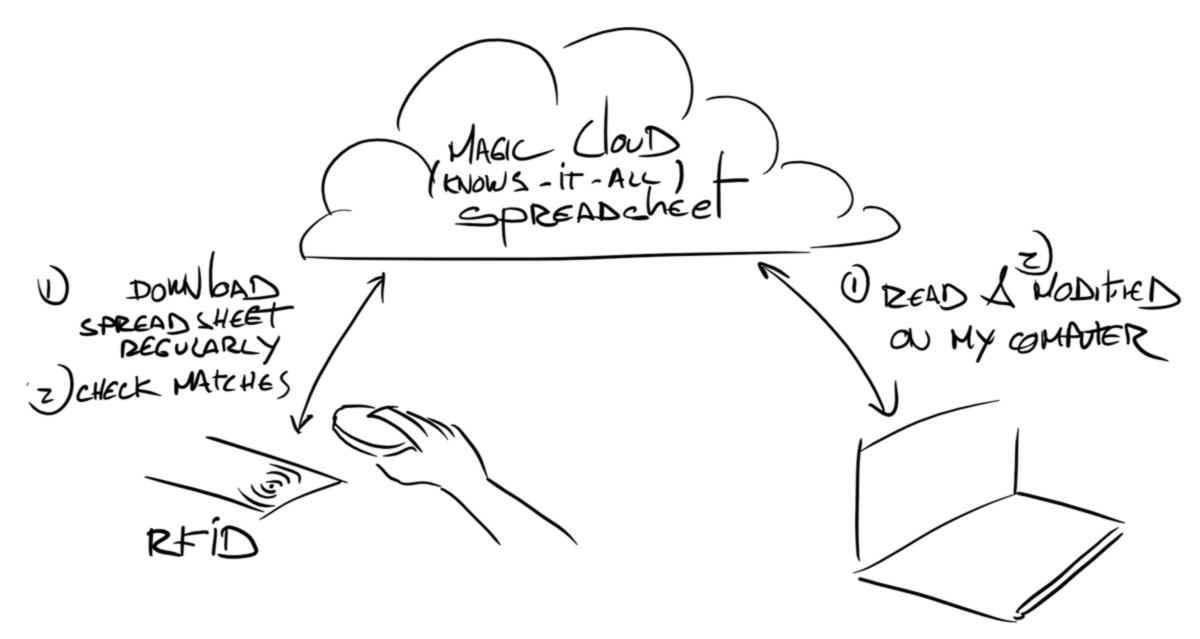
In pratice, the two options are :
The second option is tempting, however, can an online datasheet update external chip, or can chip update their own data by fetching them via the cloud without computer by their side, pushing it to them? In a word, can the chip do the job completely by itself without need of an extra computer?
Blutooth module uses less energy than Wifi module, therefore, unless I can save on the use of a computer, there is no good incentive to go Wifi.
I can see I need to do some research before moving on. I will simply use the serial of the FTDI for this board. I connect the Rx and Tx between FTDI and microcontroller and start routing. It can tell that I would like to get to know this software in more depth to save me some time in the future. For now I use basic tools to get there :
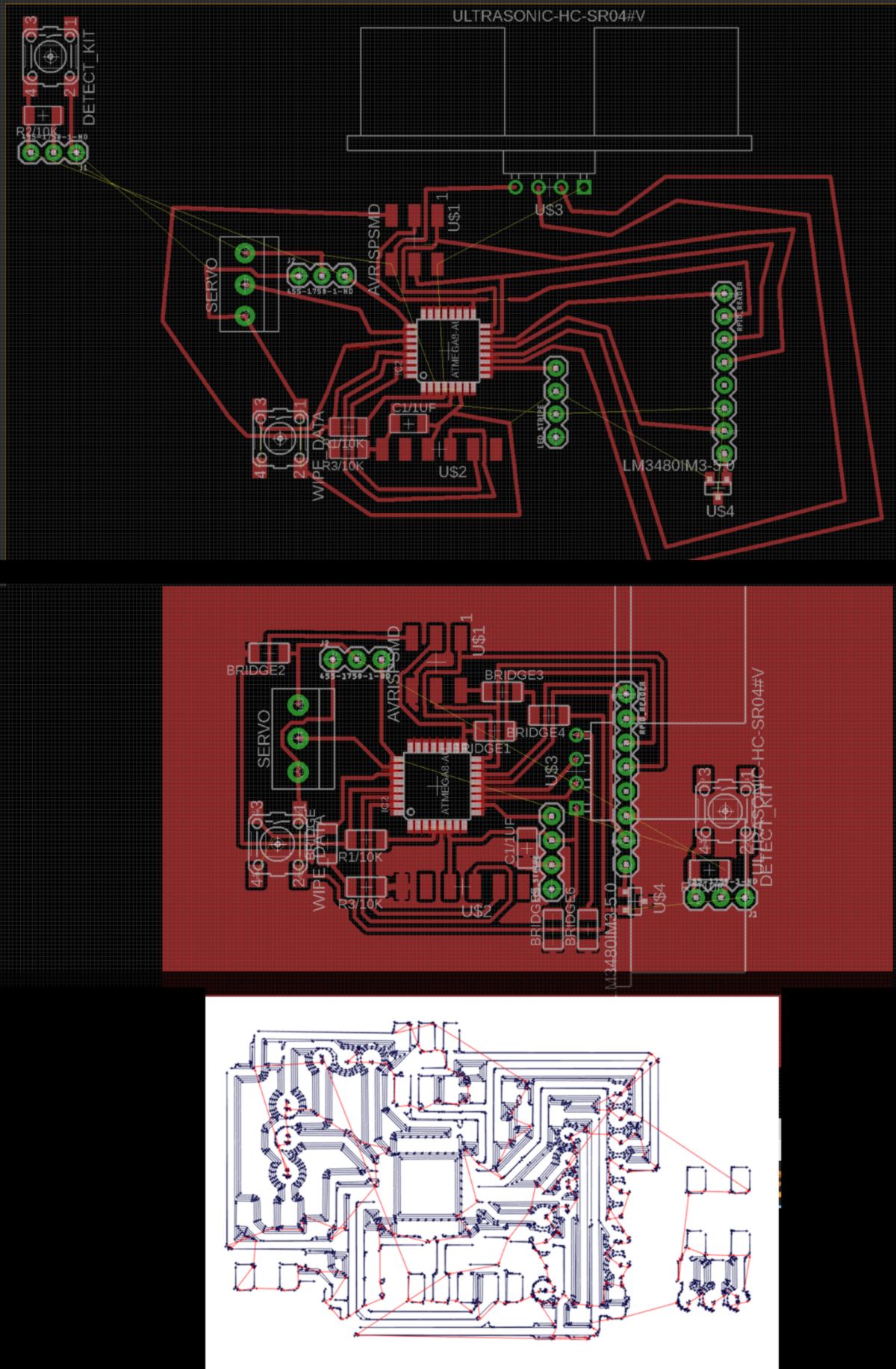
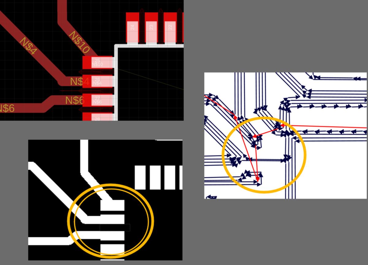
As I test the board in fabModules I noticed the spacing between pins on the microcontroller are not been cut out by the 1/64 end mill :
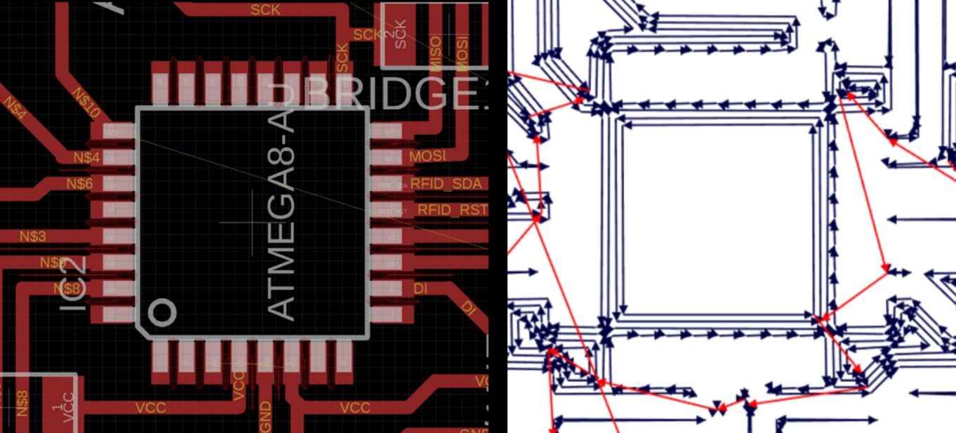
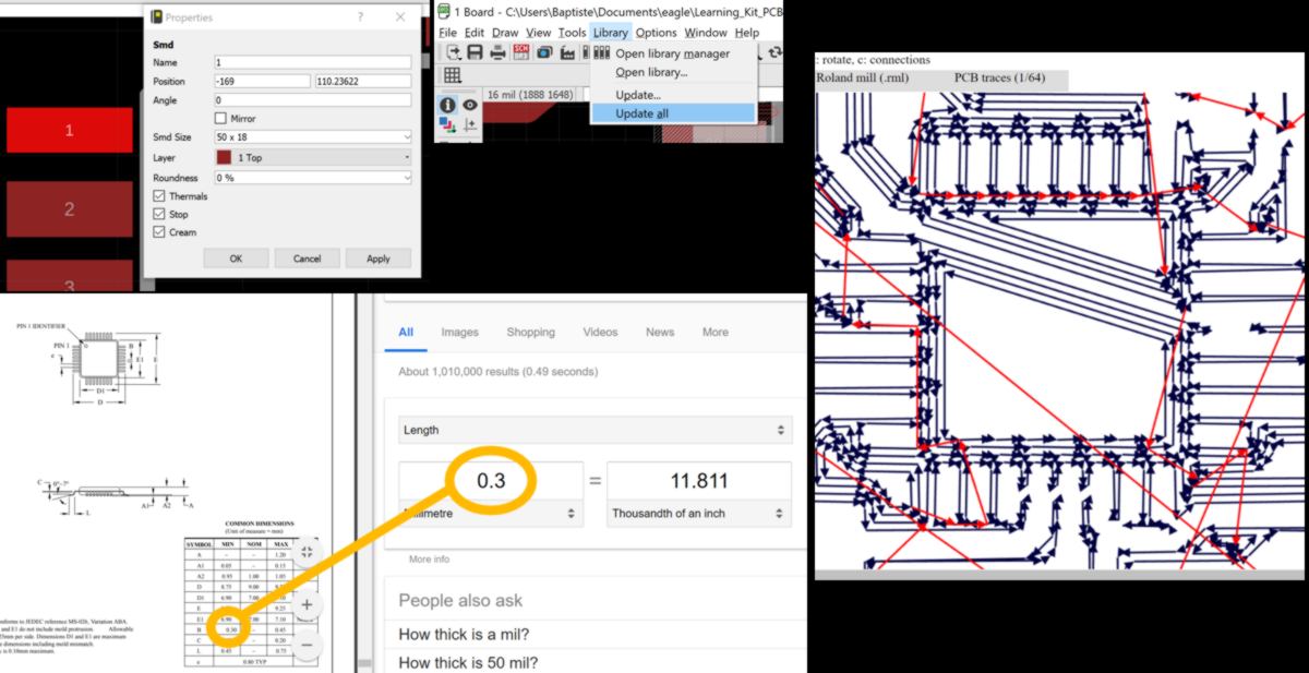
20.04.18 /How to mill this board correctly, taking into consideration the small spacing between each pin of the microcontroller? I have a look at the work ot another Fab Academy student, Dan Chen, who milled a board with the same microcontroller using a 1/64 end mill :
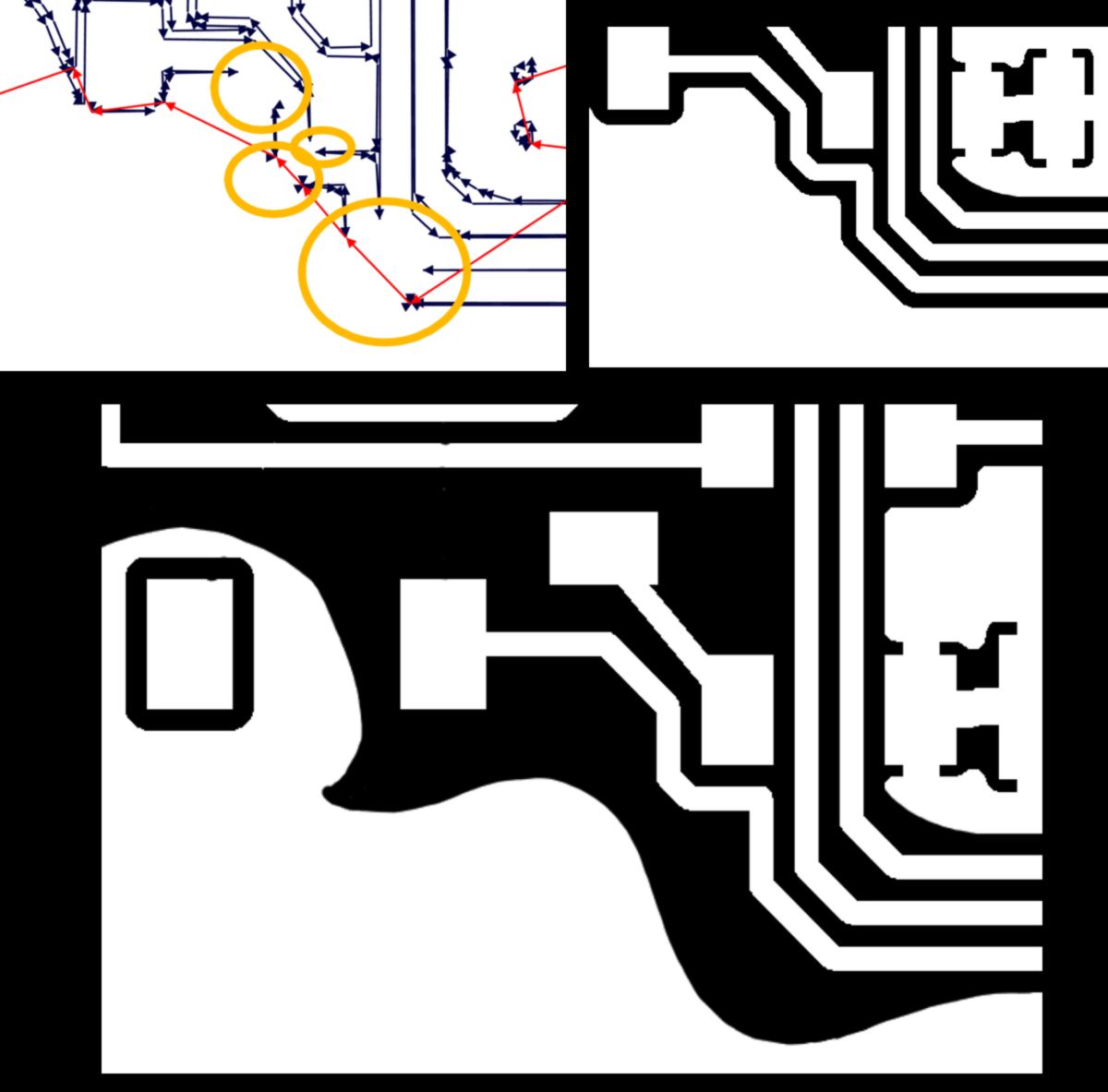
I find a video describing how to do so. I try different thicknesses, then end up checking the width of the leg of the microcontroller to get to the smaller width possible : 12mil. I also have to modify the width of the routes around the microchip.
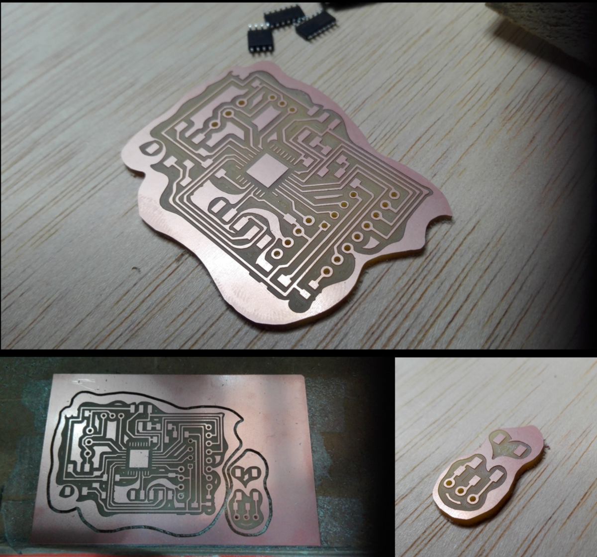
The design works almost perfectly. I make some adjustments on the .png itself and mill the board.
The weekend has started, which means I won't have access to the electronic lab until Monday. I start planning for the next assignment : interface and application programming. Now that the end of the fabacademy is near, I will use every single assignment to complete my final project.
Below is a summary of where I am at :
The educational tool requires the production of tutorials. Although they should be the first thing to be prototyped and tested, they will be designed last in my case, for the two following reasons :
The educational system requires a physical setup where the learning kits can be stored. Thanks to an aquaponic project that I was working on in parallel, I have developped a shelving system which visually emphasises what it supports. The structure is lighweight, and, since the whole system is modular, it can be extended. Some might add that the design is somewhat atypical, therefore drawing interest:
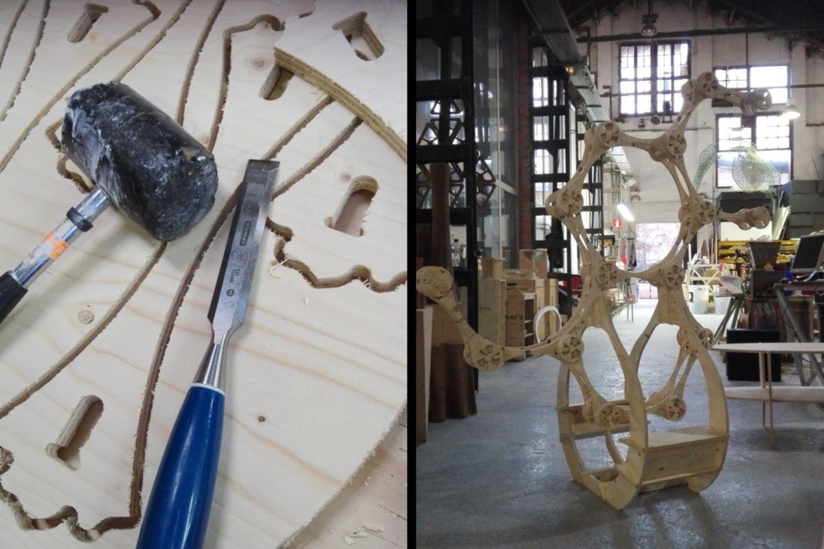
It still requires some design work for the shelves and base ( I wish to design the outer edges as well, but it is purely aesthetic, so it will wait ).
Then comes the tools and machines. With these, two issues arise : theft and safety. While some tools are relatively inexpensive and can be left unattended, some others need to be taken care of so as to get back on the shelves at the end of the day. Similarly, there is a level a responsibility related to the use of machines. Users must have some prior knowledge and experience before using them without direct supervision.
This bring about the need of a user-recognition system which allows or restricts access to tools and machines according to their knowledge and experience. In the physical world, this is embodied in some elctronics embeeded in the shelves supporting learning kits and power source of machines. I have worked on the first during my electronics assignment and will post a picture in the next update. The locking system for the power source of machine will take place in the machine design week.
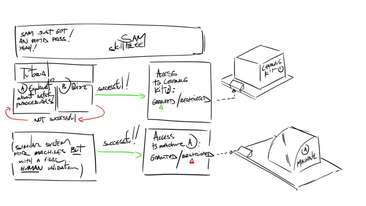
To provide both the basic knowledge about the safe use of tools and machines and keep track of the level of expertise of each user, a skill tree is required. Identical to skill trees in video games, it allows users to select their fields of interest and learn the basic theoretical knowledge before attending a course given by an instructor. Online tutorials should not fully grant users the permission to operate a machine without any instructors. Each machine is set up differently and therefore behave in its own way at a specific time, and only humans can adapt to these rapid changes to answer the complex task of teaching how to operate a machine.
This lead to the next two week's assignments : setting up a skill tree which stores level of expertise of users and attached permissions to use tools and machines, and allow communication between the storage system and this skill tree. This skill tree will be the back-end of a larger system which will add tutorials for users:
This is what I intend to do next week :