Fab Academy 2018
by JEAN-BAPTISTE NATALI
jbnatali@gmail.com
how to make (almost) anything final project
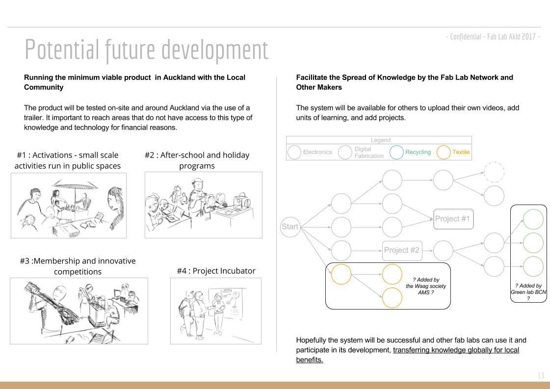
Attending the Fab Academy in Barcelona, I document the development of my final project: developing an educational platform where makers can compile the "how-to" of their successful projects and share it, spreading knowledge in digital fabrication across fab labs worldwide.
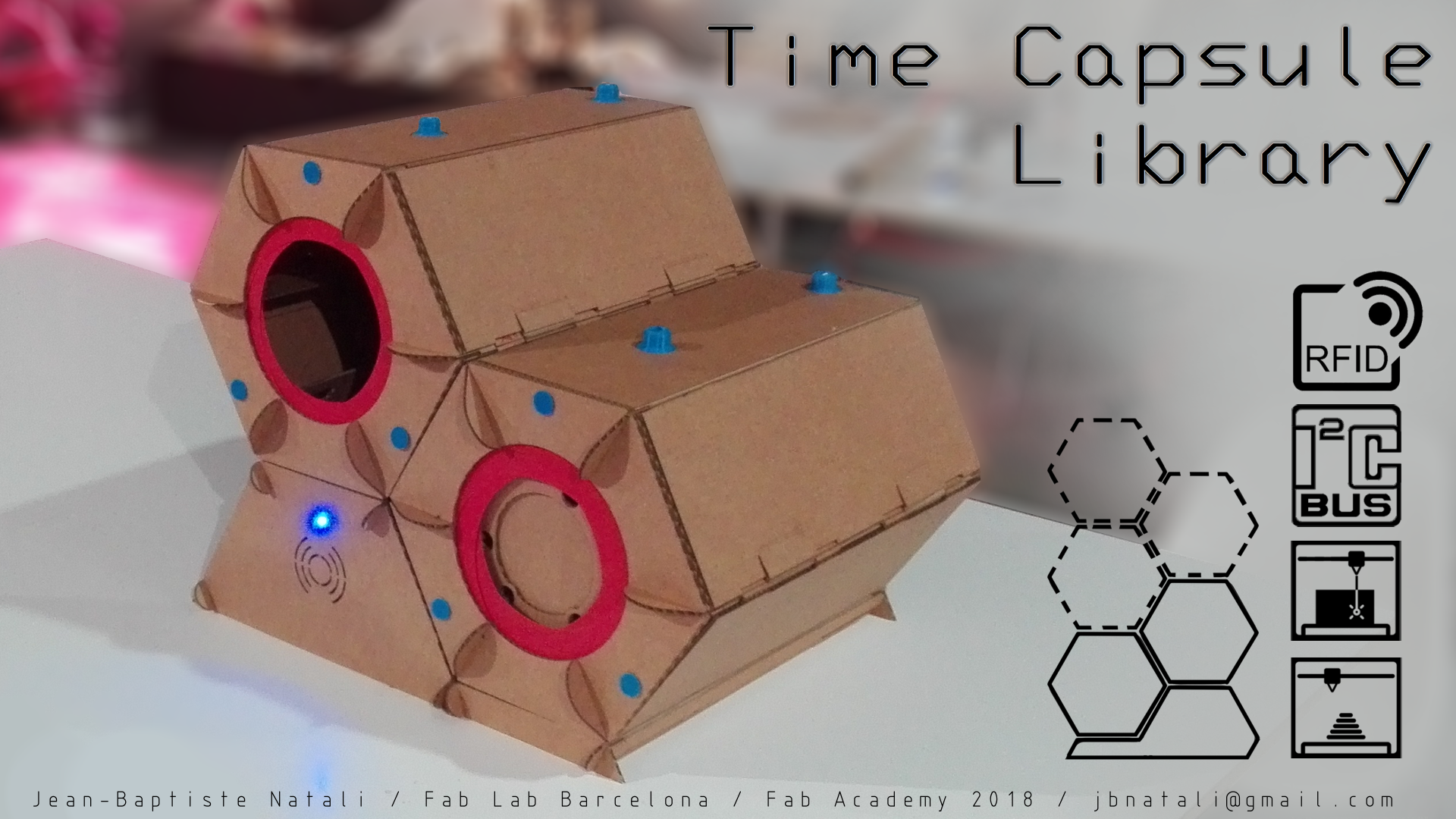
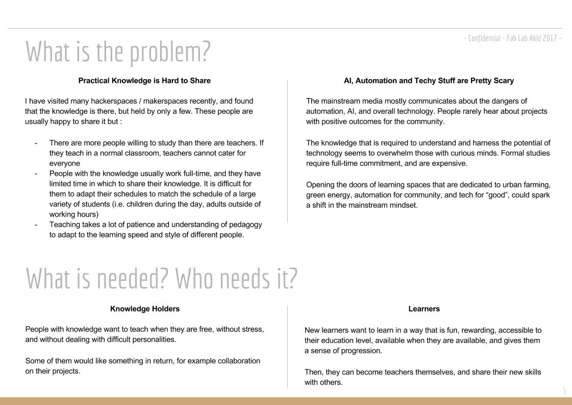
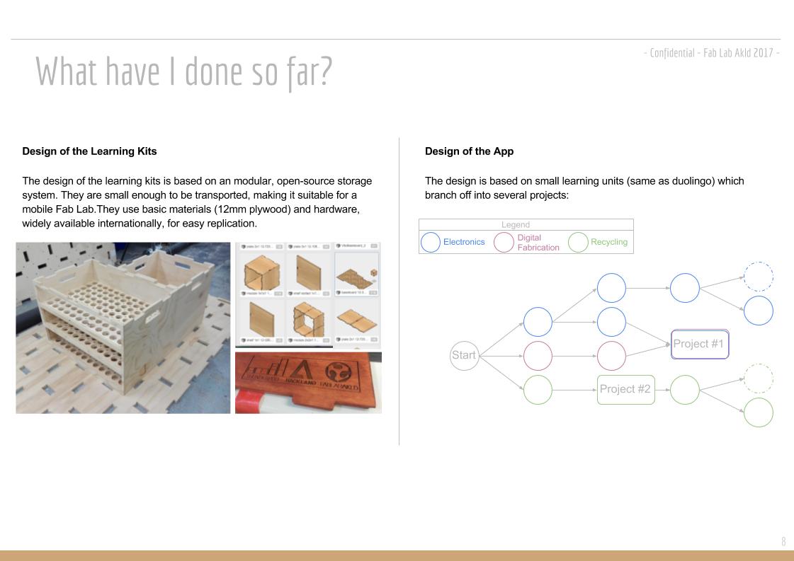
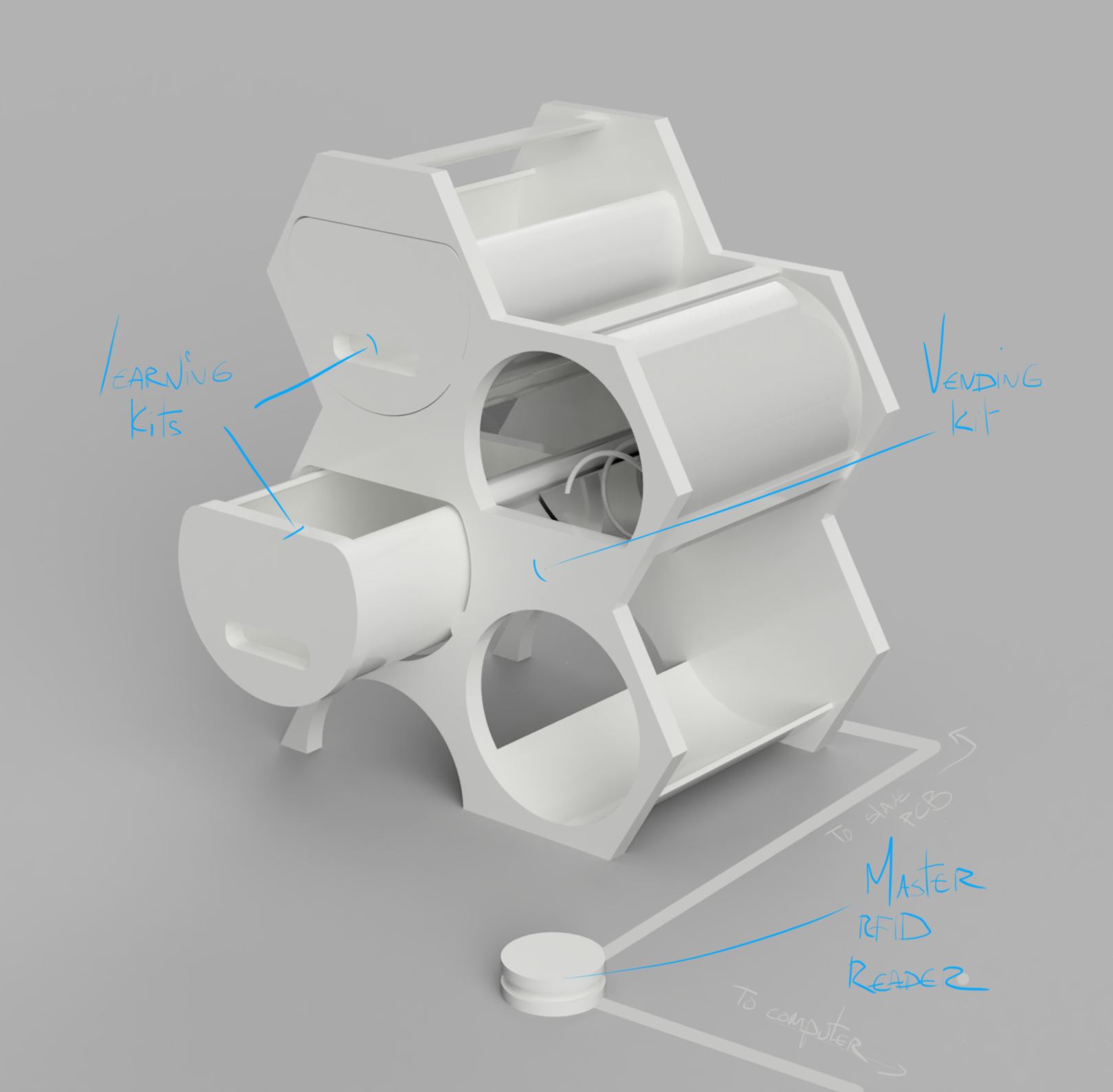
With the objective to enable new members of a Lab/Makerspace to autonomously access knowledge and tools safely, I have developed a working prototype for a storage system containing learning kits.
Each kit offers an example of a fabrication technique specific to a place, an era or a culture. Hence I started developing this prototype with the concept of "time-capsule" in mind, coming from the past... or from the future. The inital concept was inspired by this book, recommended reading.
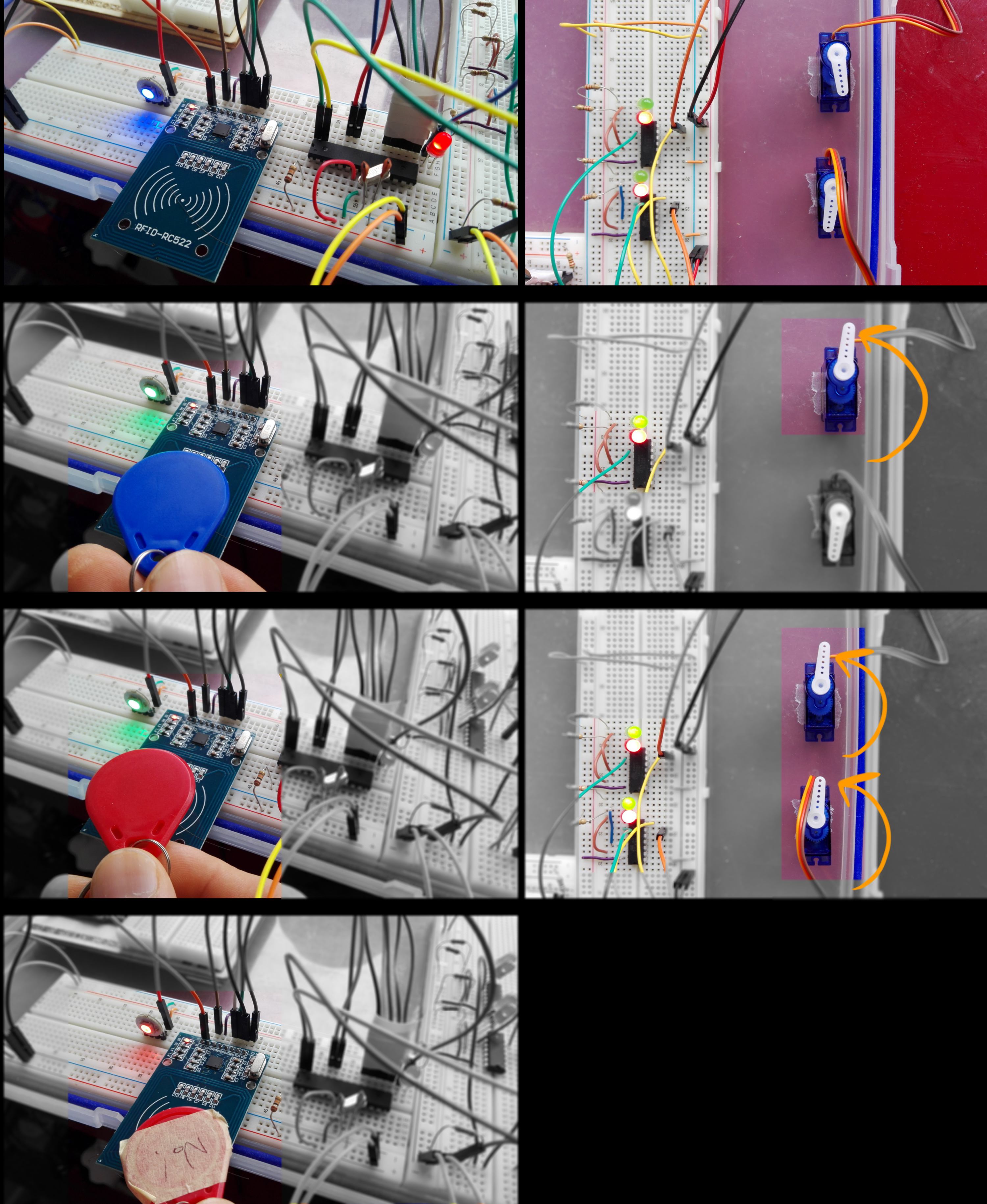
Using assigned tags, two users unlocks access to learning kits specific to its level of knowledge.
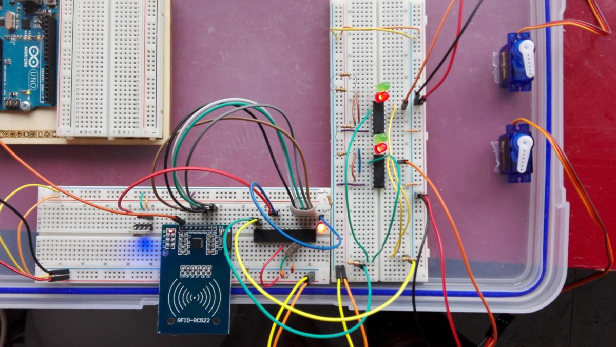
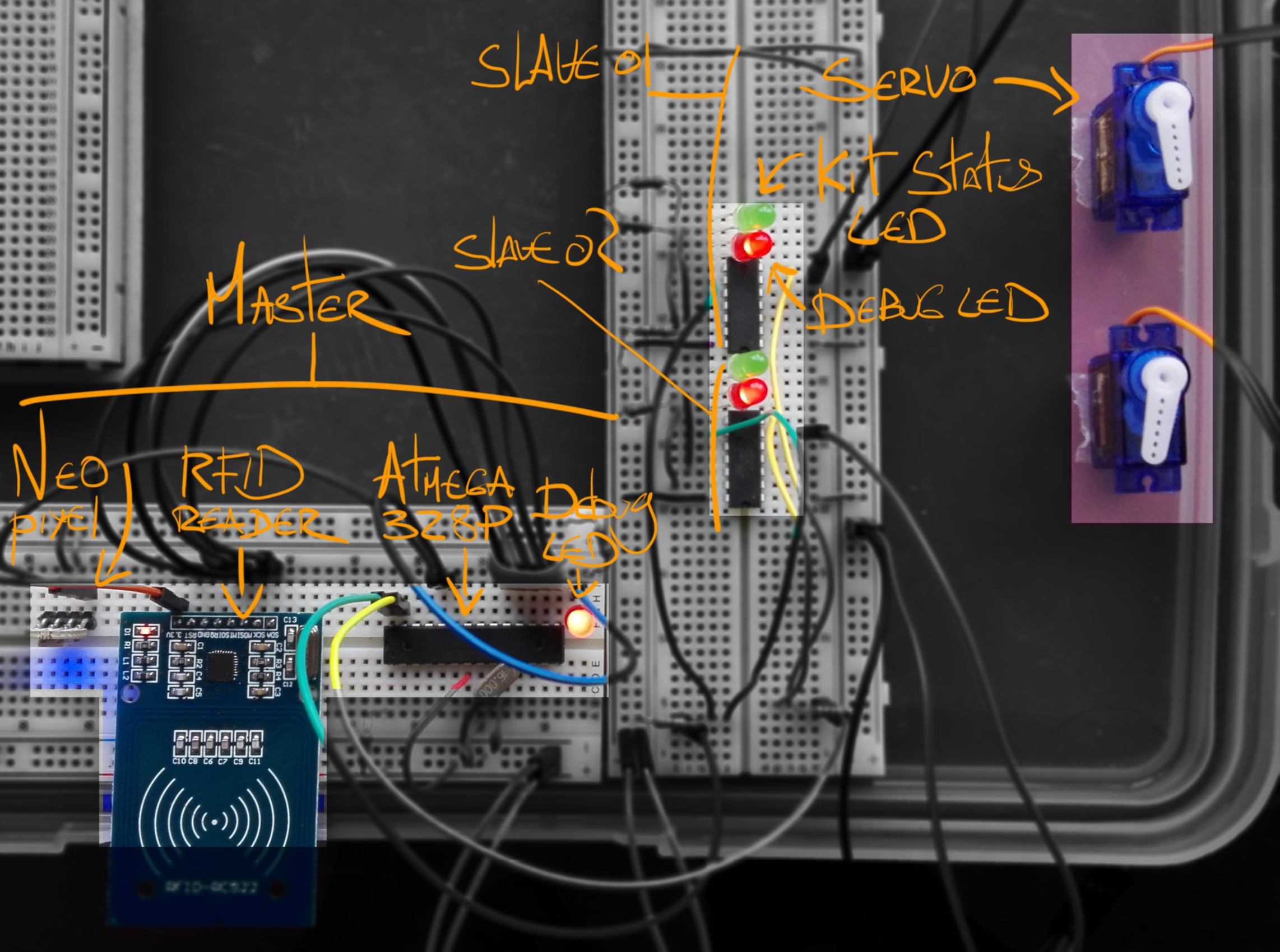
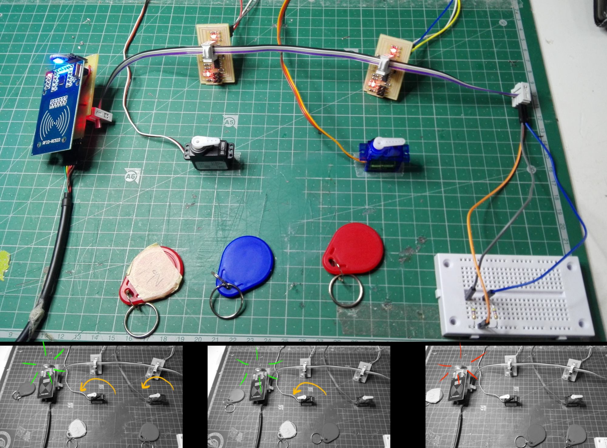
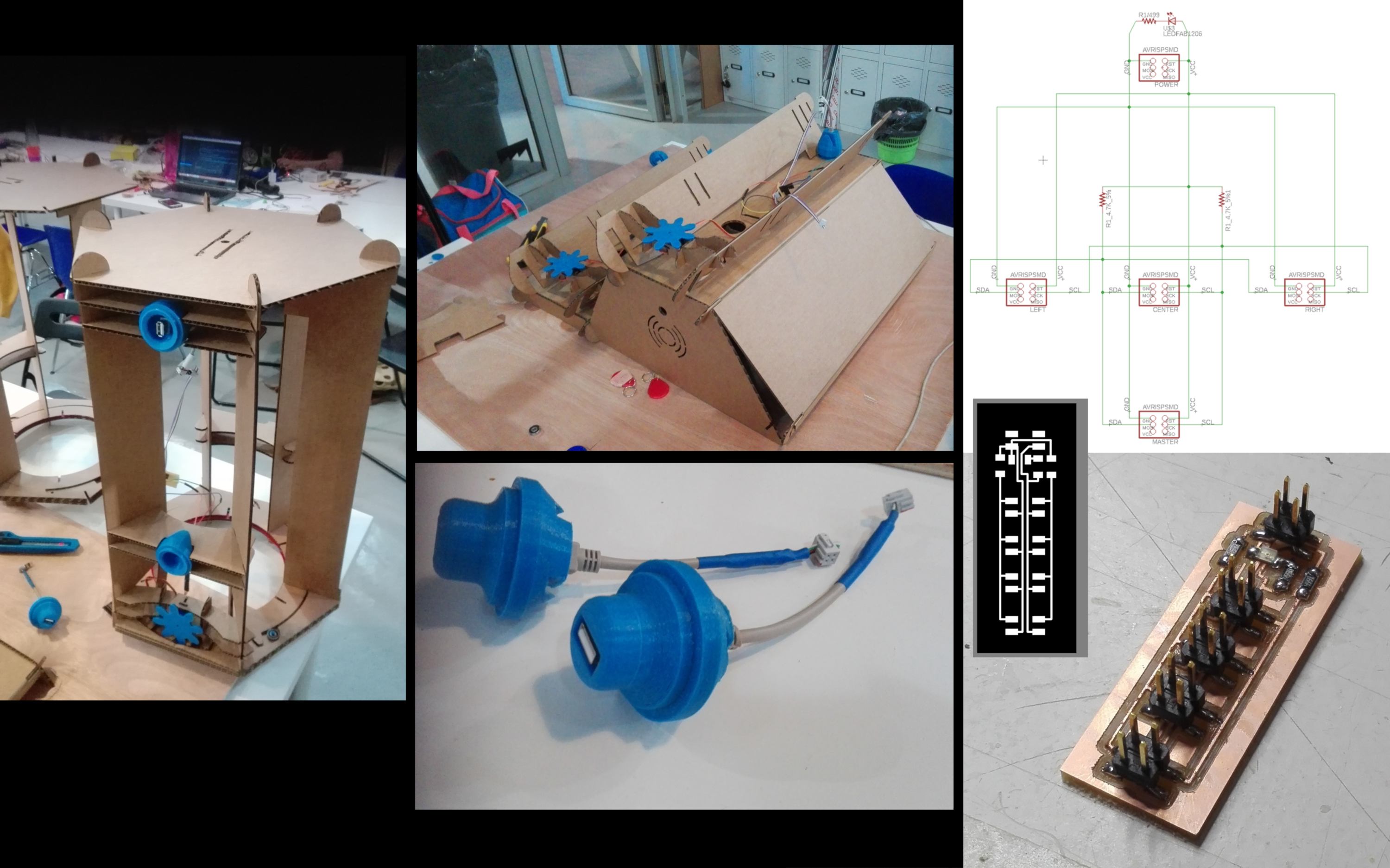
The RFID tags are read by a RC522 reader. An ATMEGA328P storing the valid IUDs grants or refuses access to time-capsule casings and provide an immediate visual feedback. If valid, a signal is send though an I2C network to all corresponding kits, enabling the opening of an iris via rotation of a servo. Once the user has taken time-capsules off the shelves, casing can be locked back by swiping the RFID card.
level of development :
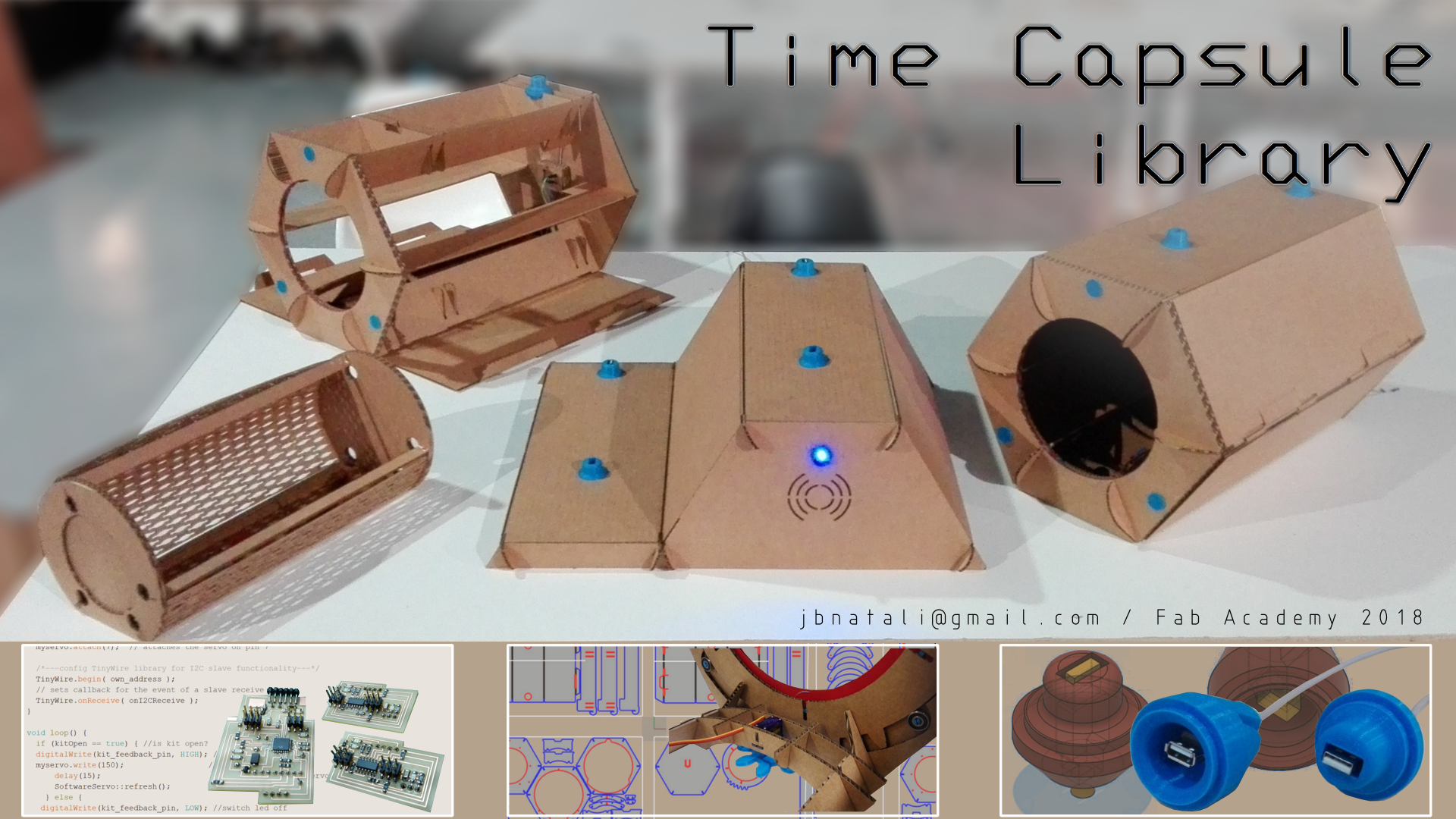
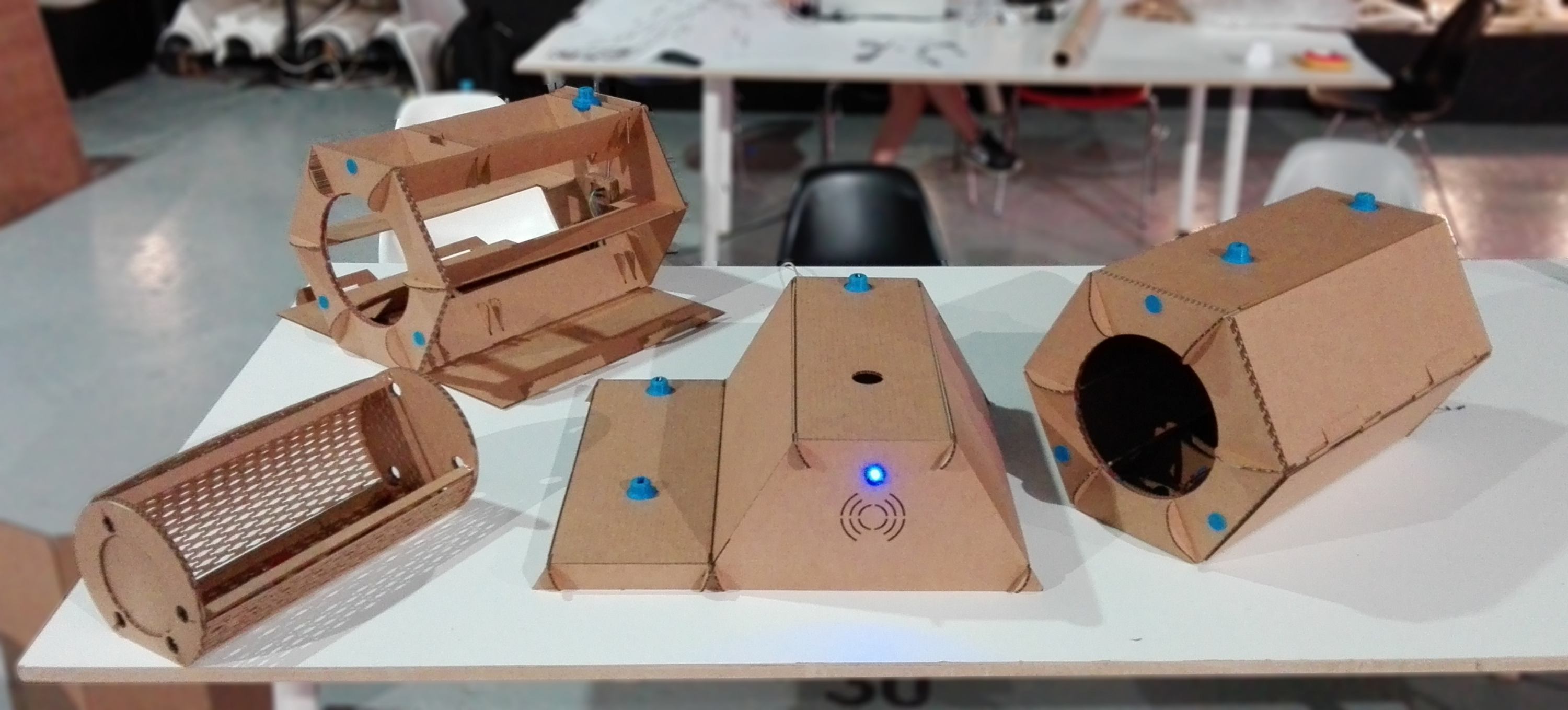
The design is a functioning prototype, ready for testing. The system is modular, and can hold up to 5 time-capsule casings before a base extension is required. The shapes used refer to the theme. The materials have been selected for rapid prototyping and are not representative of the desired final result.
timeframe for development :
The design and fabrication of the this system was entirely completed within the last two final weeks of the Fab Academy. One aspect of the Electronics was looked into prior to this timeframe during week 12 : output devices .
digital fabrication techniques used :
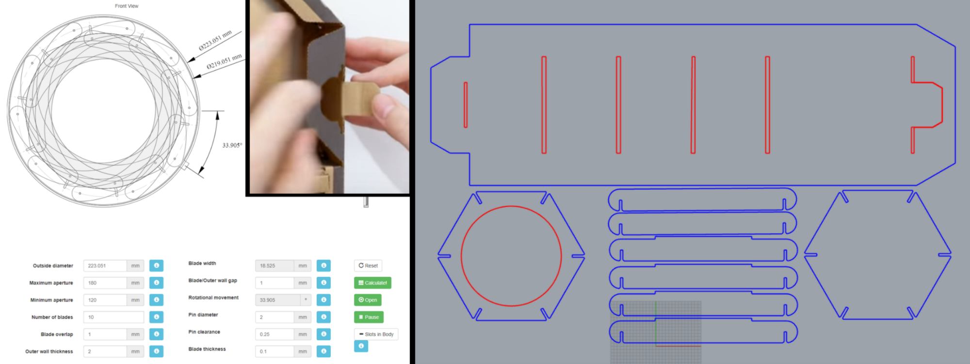
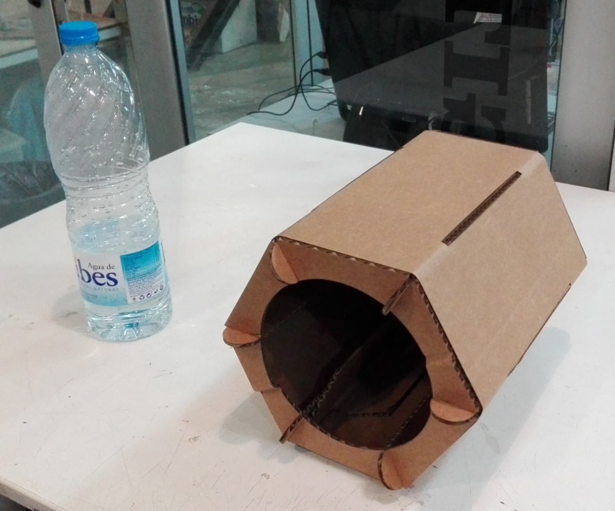
Two techniques were used : laser cutting (structure, shell) and 3D printing (connectors). All elements were designed in Fusion360 and Rhino:
about the electronics and programmation :
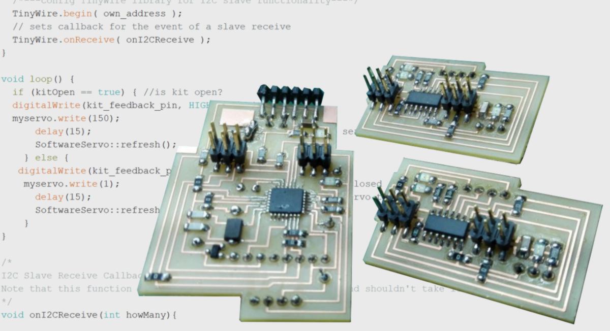
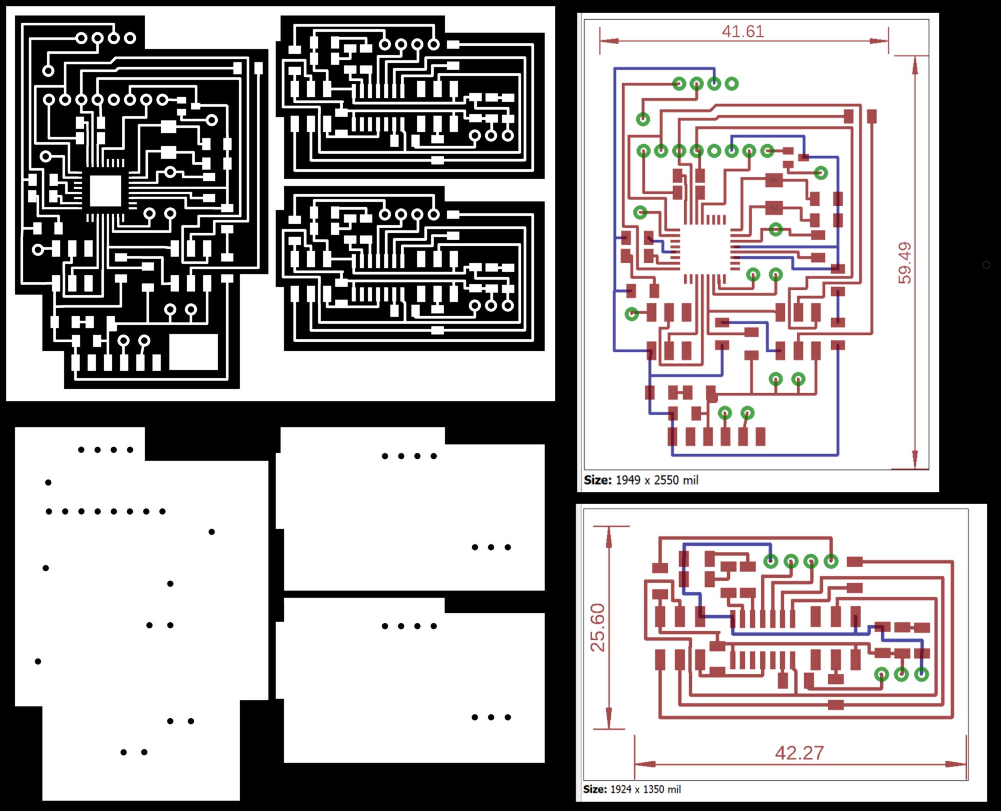
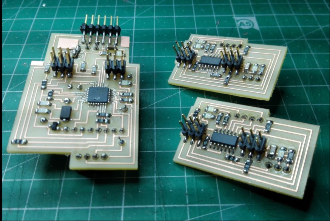
The Master board (hosting an ATMEGA328P, an RFID reader and a Neo-Pixel) and Power Board are located in the base. Each casing contains a slave board (hosting an ATtiny44 and a servo). All boards were designed in Eagle:
assembly :
Each component is a press-fit kit. Glue was only used for the casing of the PCBs :
cost :
The estimated material cost for each capsule and its casing is around 8 USD. The cost of the base is around 10 USD. You can find the Bill of Material in the "files for download" section below.
acknowledgment :
I wish to acknowledge the contribution from all programers behind the many libraries I used for this project : Massimo Banzi, David Cuartielles, Tom Igoe, Gianluca Martino, David Mellis, BroHogan, jkl, LucullusTheOnly and the online AVR community relentlessly answering on forums.
I also wish to thank Javi for inspiring me with his work on the first iris made during the machine week, as well as DangerousBeans passing me the virus of designing with hexagon and thinking modular.
license :
There are aspects of the licensing that requires further researches to enable this design to reach its target : gathering and spreading knowledge. Until this is in working order, this design is licensed under a Creative Commons Attribution-NonCommercial-ShareAlike 4.0 International License.
An interface tracking the progress and unlocking new activities for users is yet to be developed, alongside a visual remodelling of the physical items. Then curated content will be selected and made available for each capsule, and testing will then begin with both young (7/12yo) and adult audience.
Hopefully the use of this kit will expand beyond FabLab Barcelona to reach other Labs and places of learning.
project replication :
All you need to replicate this project can be found right here. This also includes design files - electronics design, object design, programmation, bill Of material - so be my guest, and send me your feedback / hero shot of your version if you get the chance : jbnatali@gmail.com. Thank you!
Please find below the development of this project. The concept was first thought of in 2017, and was developed over the two final weeks of the Fab Academy. This development is presented in chronological order, starting in January 2018.
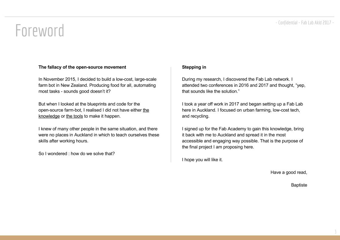
20.01.18 / I drafted my final project before heading to Barcelona. Find below a comprehensive description of it:
15.05.18 / We are one month away from the end of the Fab Academy. Below is an update of my final project.
My final project can be divided in several parts:
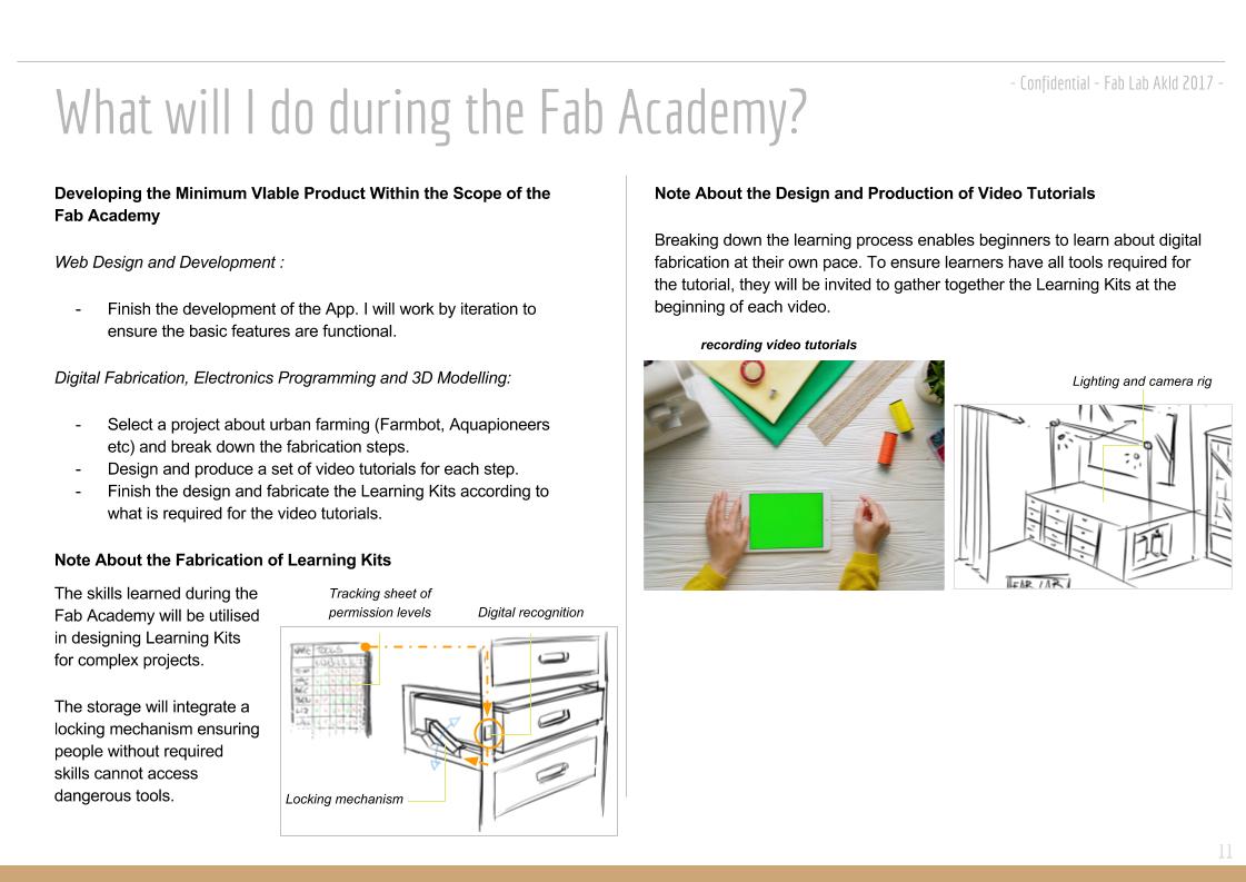
- production of video tutorials;
- stand for video recording;
- digital interface, front end, displaying the skill tree and video tutorials available;
- digital interface, back end, communicating with the locking system of each learning kit;
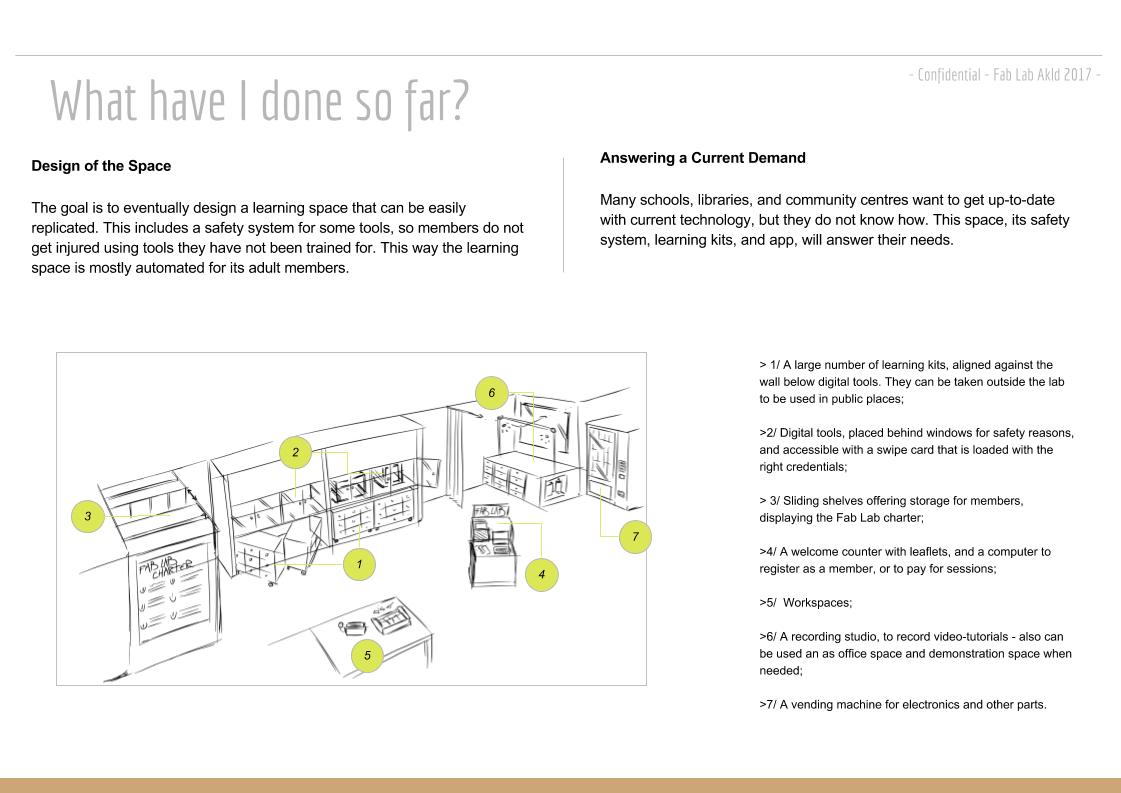
- working space for user;
- storing system for learning kit;
- vending machine for material.
Some of these parts could by themselves be a Fab Academy Final Project. The whole project is too big for a single student. therefore I went to Milan where two Fab Academy students are developing on a similar educational project called Fab Kit. We discussed about a potential collaboration.
Fabkit will be deployed in refugee camps, therefore, due to the inponderable of such situation, they wish to rely on paper or written tutorial rather than videos. There is no digital interface planned. Only one person - the instructor - has access to the tools, machines and materials, and give access to learners. These contraints limit our opportunity to immediately collaborate, excepted to produce and curate the content of tutorials.
To develop the prototype in the next 30 days, I will stick to the minimun required and make use of what I have already developed in the last 5 months. I will make:
-one working space for user, comprising a user recognition system based on RFID card connected to a computer. This recognition system will act as a master in an I2C network;
- two learning kits, based on the same design, with a locking system. these locking system will act as slave in an I2C network;
- two video tutorials, one per learning kit. One of them will be accessible straight from the start, the other will be unlocked when the first tutorial is completed;
- one material kit, required to make the second tutorial. It will be located in a vending machine re-using the design of the learning kit. The vending machine will charge the digital credit of the user;
- a structure holding the learning kits and vending machine. This structure is modular, so extra learning kits can be added later on;
- a minimalist digital interface, showing the skill tree, with a link to the videos. For the purpose of this prototype, part of the interface will display extra information such as the credit of the user and who is using what learning kit.
01.06.18 /I have until the 11th of June to fabricate my final project - roughly 10 days. Below is my schedule :
01/06 : prototyping electronics
02/06 : design PCB
03/06 : design structure and kit
04/06 : milling, stuffing and programing PCB
05/06 : fabrication structure and kit
06/06 : production video and slide
07/06 : documentation
The last four days are safety buffer to finish what has not been finished.
I prototype the electronics :
Overall view :
Summary of the design :
Behavior :
The WIP code for all microcontrollers can be found here. I will update the wiring in the final documentation.
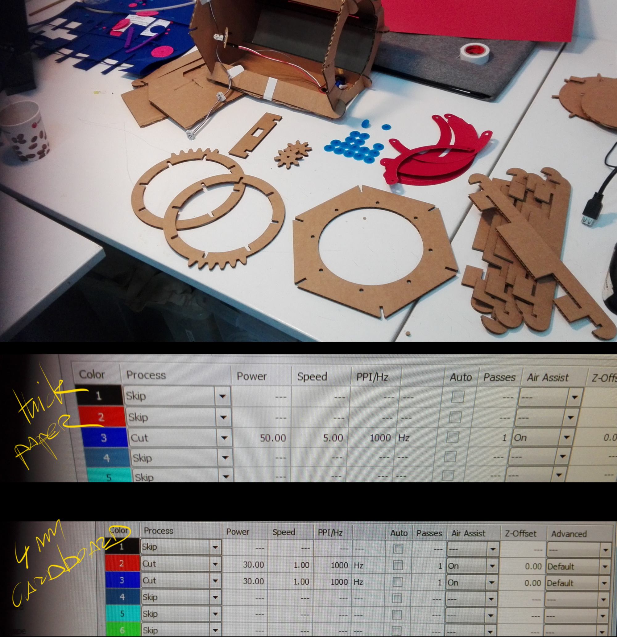
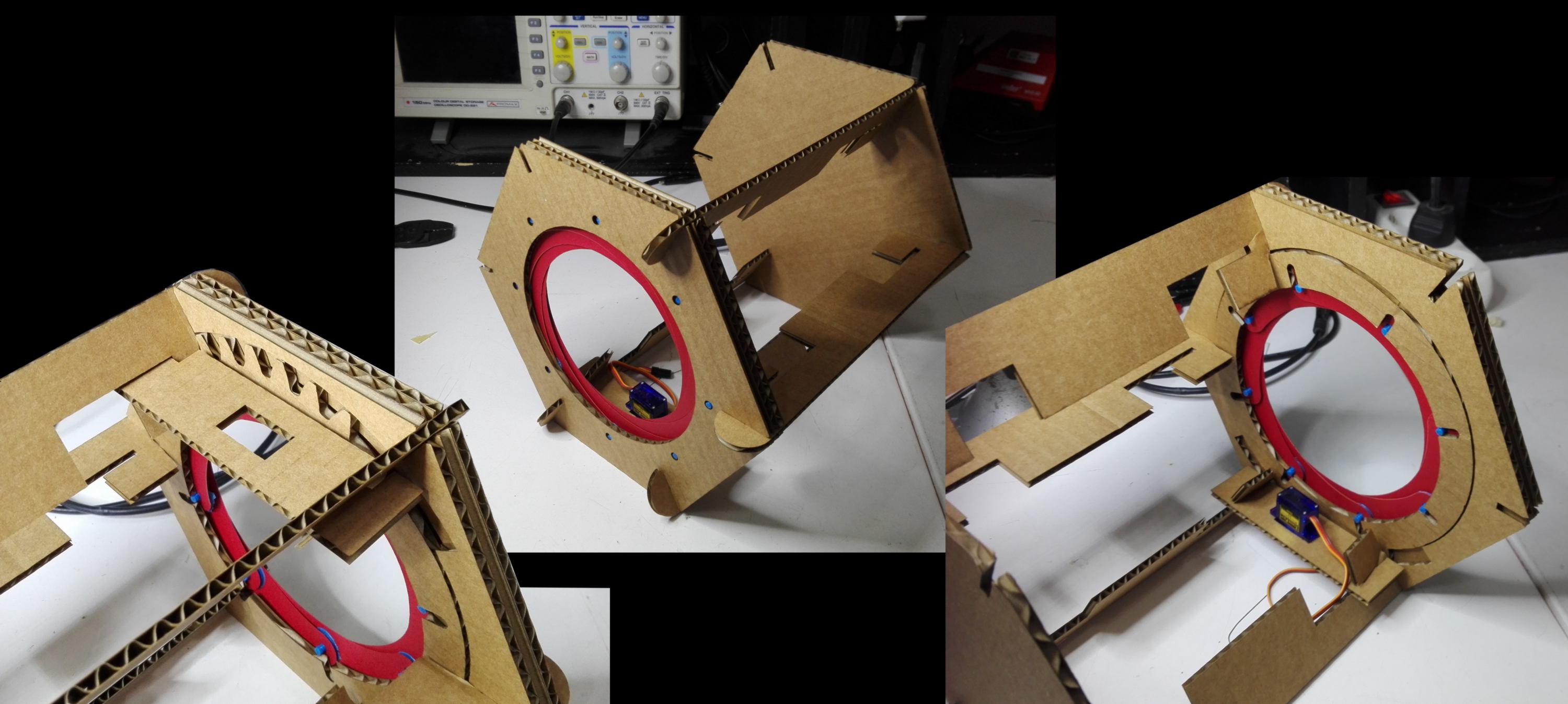
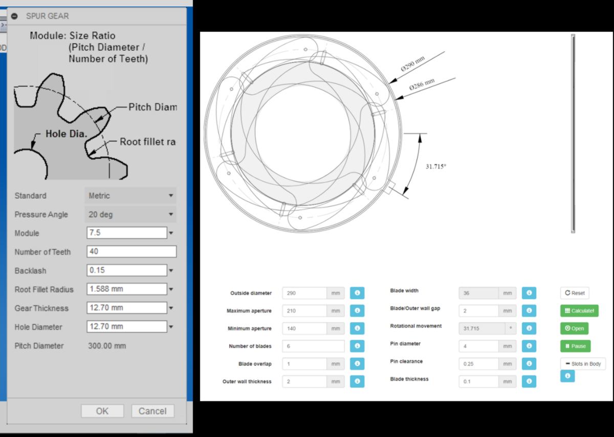
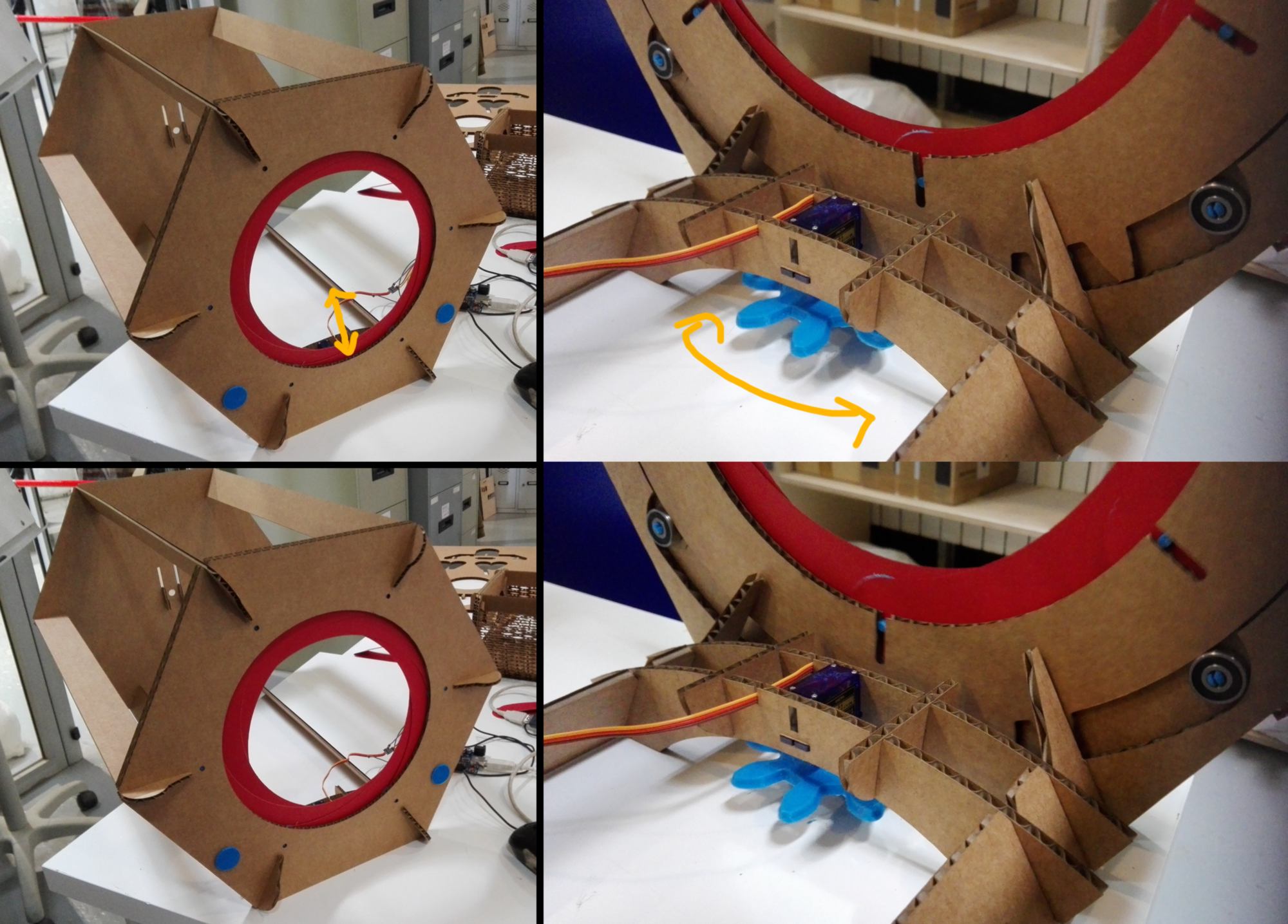
06.06.18 /I carry on with the design of the iris. I fabricate the mechanical design and actuate it :
Testing code, thanks to BARRAGAN and Scott Fitzgerald :
/* Sweep*/
#include
Servo myservo; // create servo object to control a servo
// twelve servo objects can be created on most boards
int pos; // variable to store the servo position
void setup() {
myservo.attach(9); // attaches the servo on pin 9 to the servo object
}
void loop() {
for (pos = 70; pos <= 180; pos += 1) { // goes from 70 degrees to 180 degrees - smaller range than expected
// in steps of 1 degree
myservo.write(pos); // tell servo to go to position in variable 'pos'
delay(15); // waits 15ms for the servo to reach the position
}
for (pos = 180; pos >= 70; pos -= 1) { // goes from 180 degrees to 0 degrees
myservo.write(pos); // tell servo to go to position in variable 'pos'
delay(15); // waits 15ms for the servo to reach the position
}
}
I know know that I have until the 15th to finish my project. I also realise I can break down my final project into smaller chunks. The design consist in several steps : - 1/iris, 2/connectivity, 3/ packaging of the base and 4/packaging of the learning kits. I re-plan my next week :
01/06 : prototyping electronics
02/06 : design PCB
03/06 : design structure and kit
04/06 : milling, stuffing and programing PCB
05/06 : design of Iris
06/06 : fabrication of Iris / design of connectivity
07/06 : fabrication of connectivity
08/06 : design of the base and kits, day 01
09/06 : design of the base and kits, day 02
10/06 :
11/06 :
12/06 :
13/06 : production video and slide
14/06 : documentation
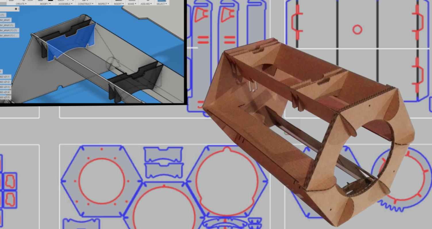
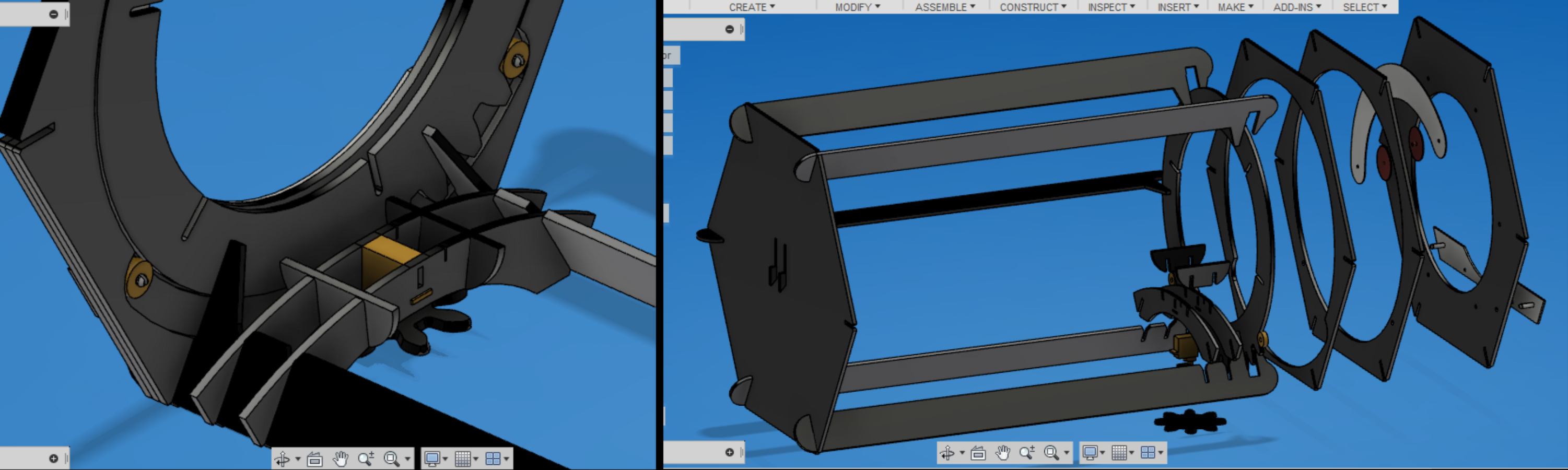
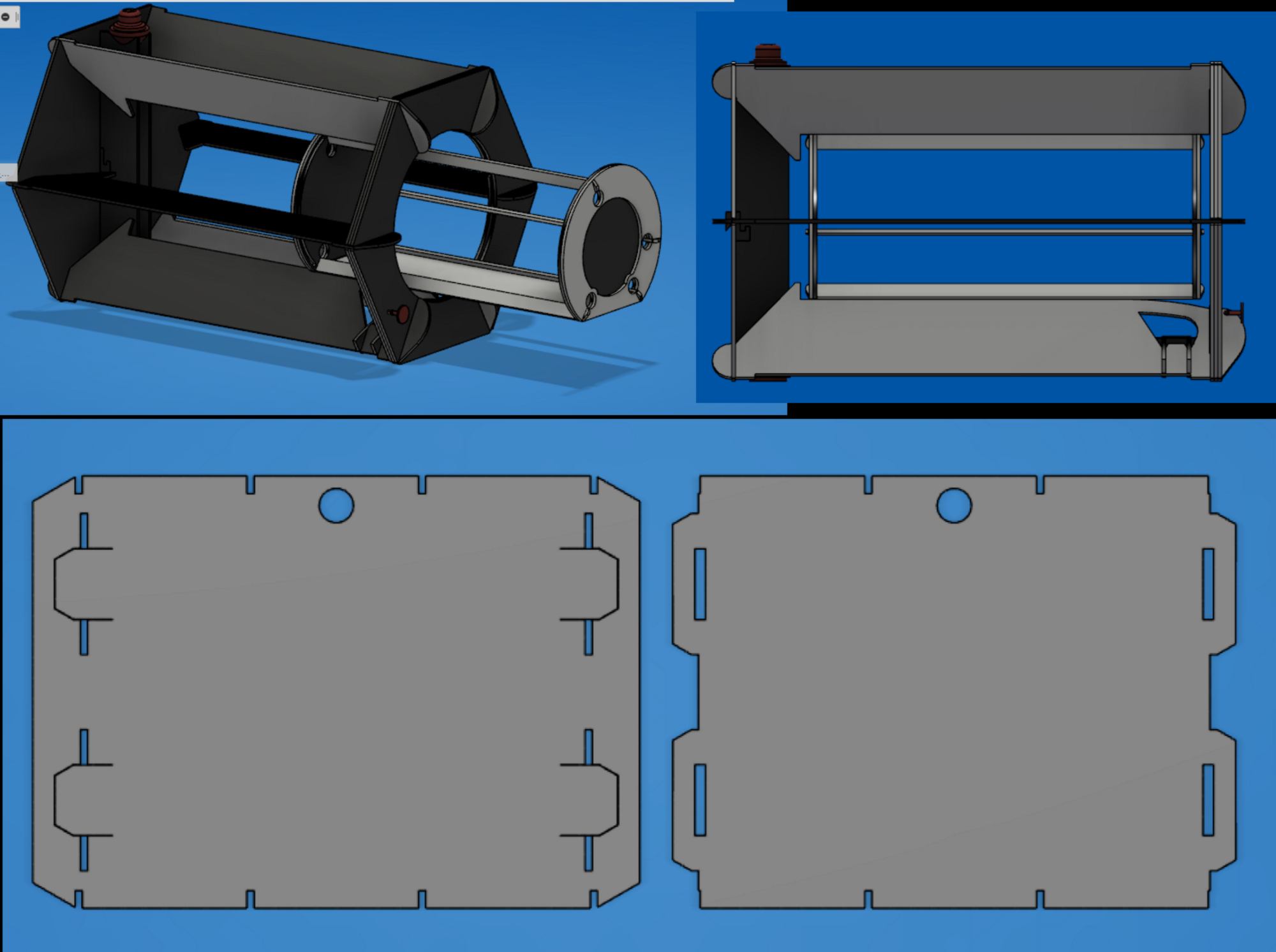
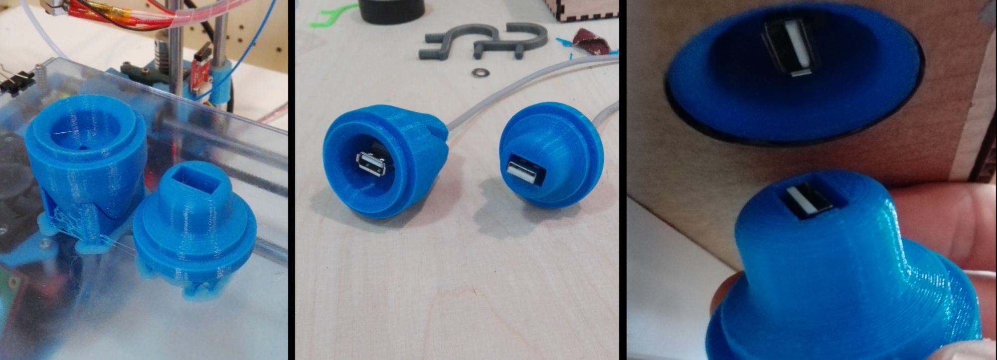
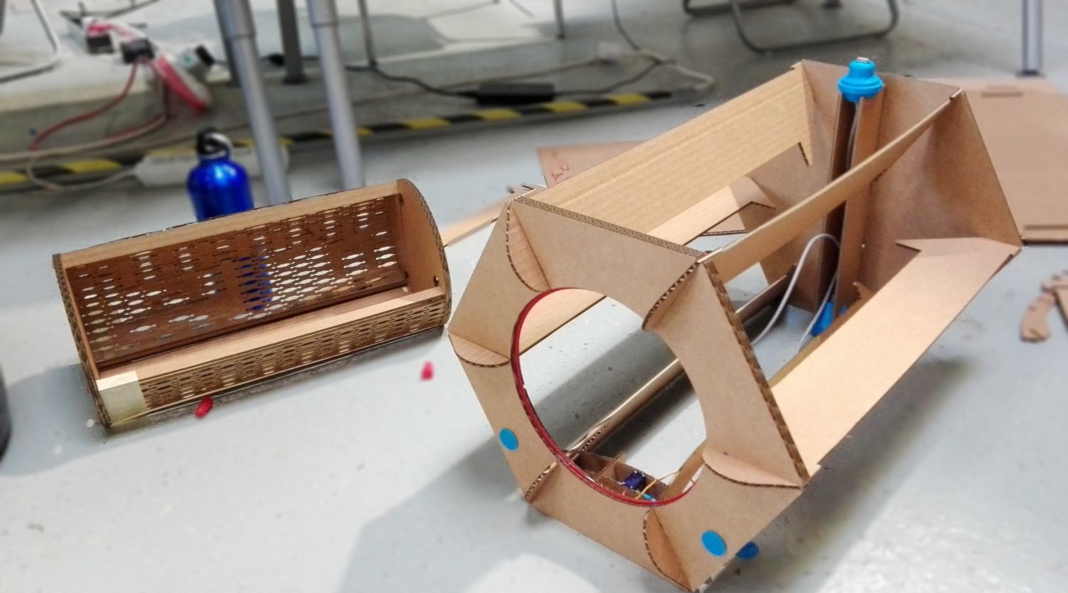
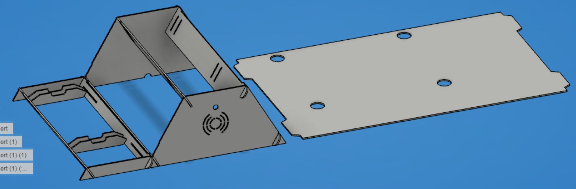
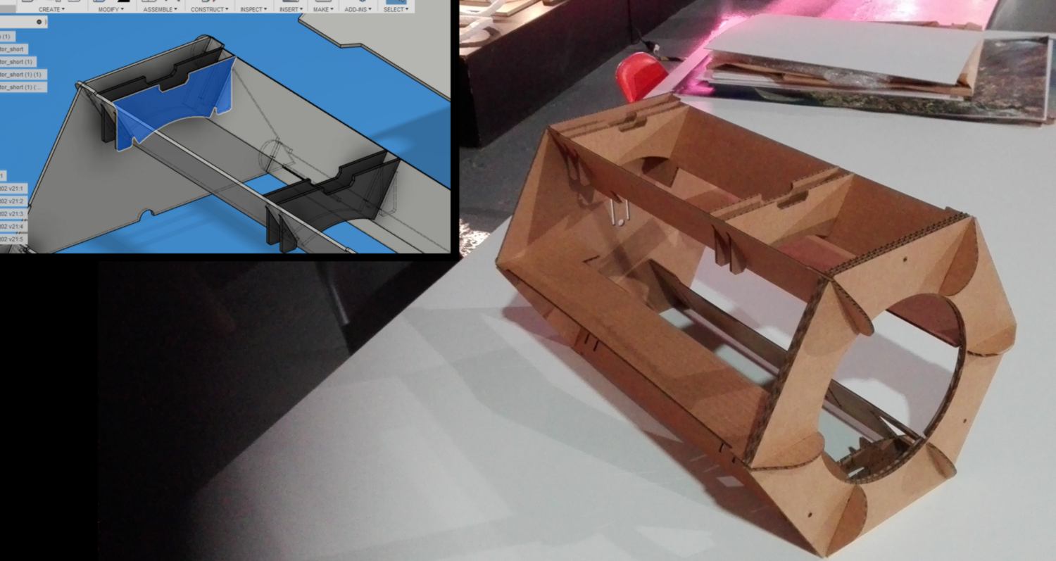
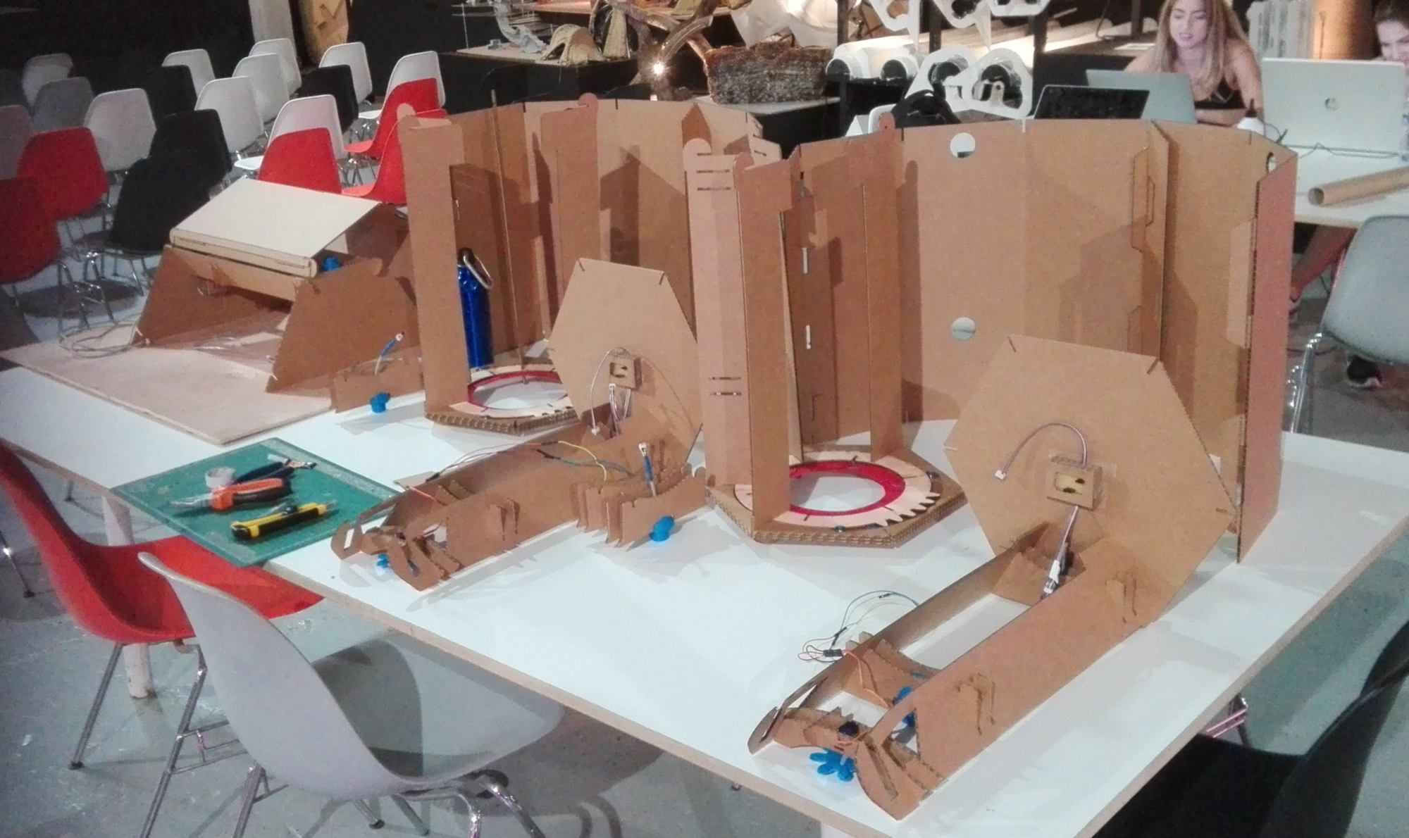
08.06.18 /I designed the USB connections between kits and designed the casing for the kit. I also designed a drawer and the structure it will rest on :
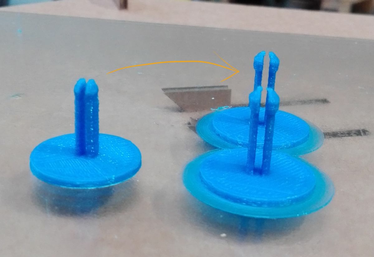
top and bottom connectors are now doubled to ensure extra modules added on top of each other are aligned and stable. They are sitting on the transversal structures to leave space for the drawer.
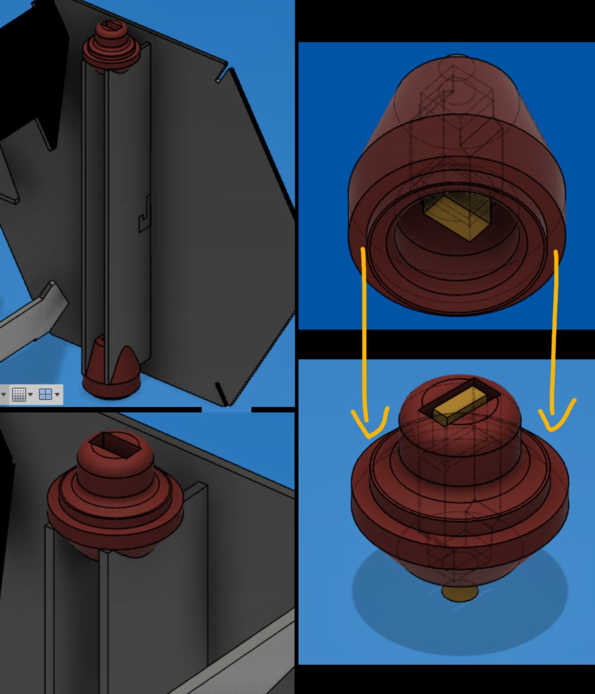
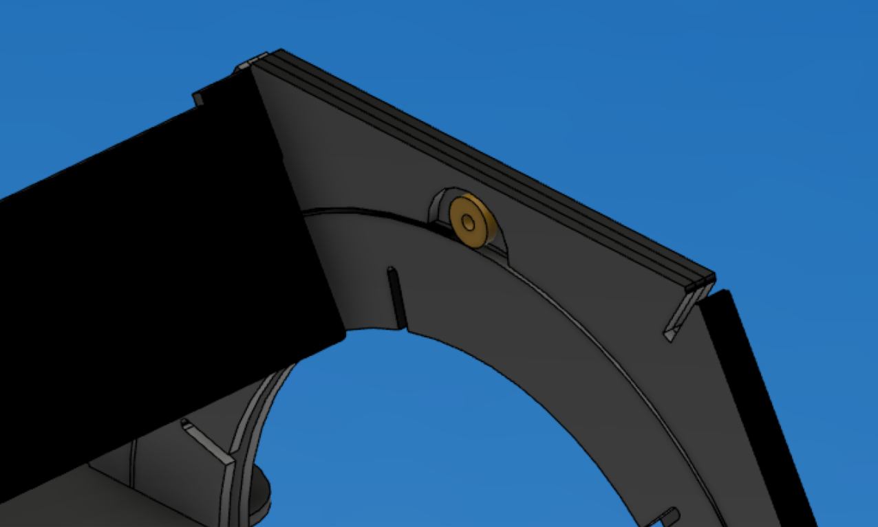
Addition of an extra bearing to keep the actuator in position.
Re-design of the pins holding the bearings for a tighter fit.
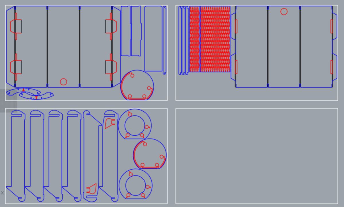
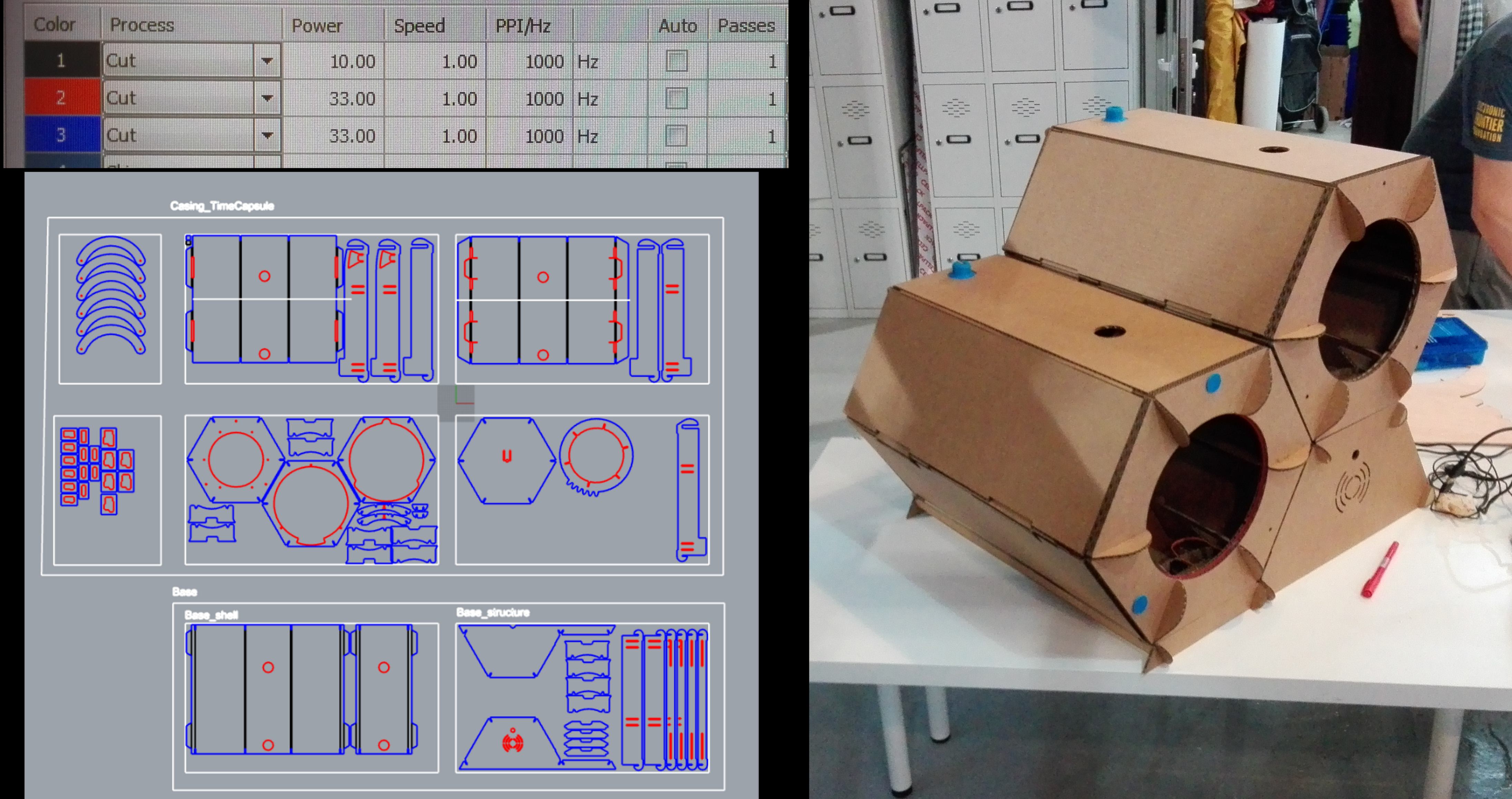
New cut for tomorrow.
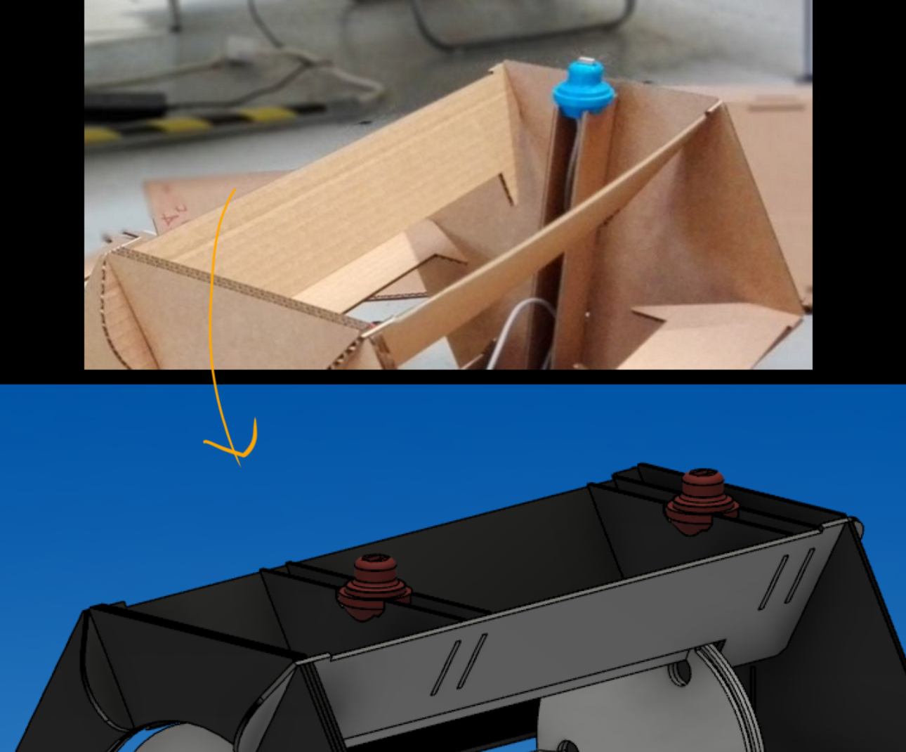
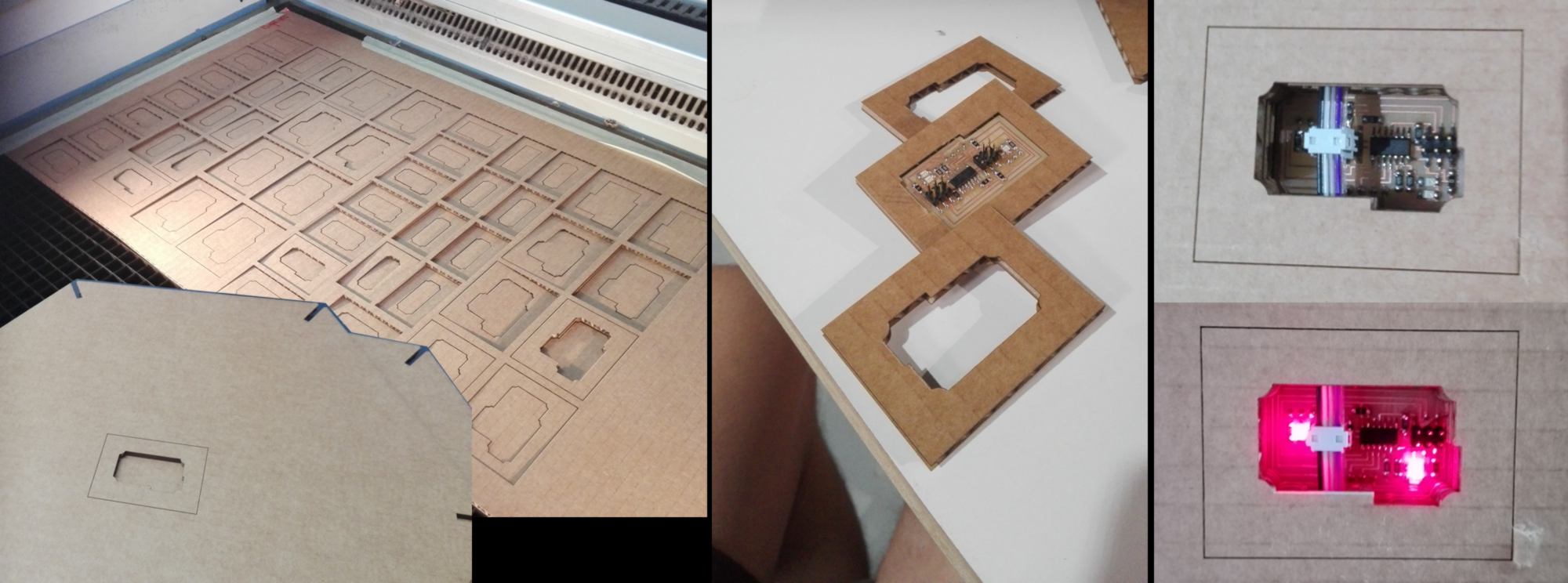
12.06.18 /Over the last couple of days I finished the cardboard design and the electronnics (setup and production of final items).
I corrected the support for the USB plug so they are more study and easier to assemble
correction of the first kit and fabrication of the second kit
wiring and producation of an extra PCB for powering and adding pull-up resistor for the I2C network.
The designs files (rhino + eagle) can be found here .
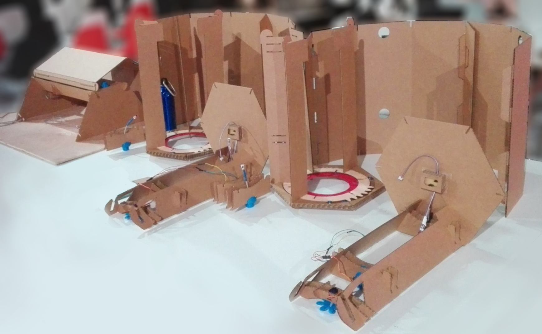
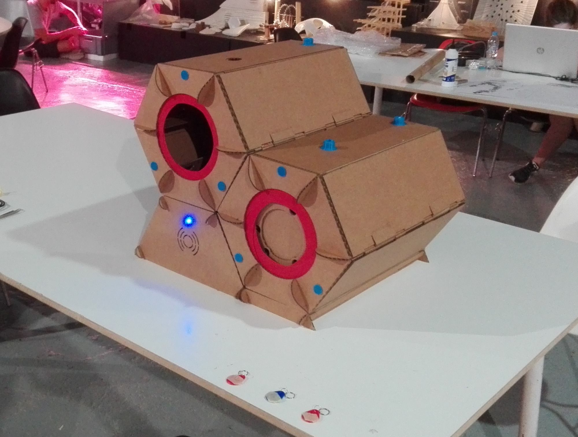
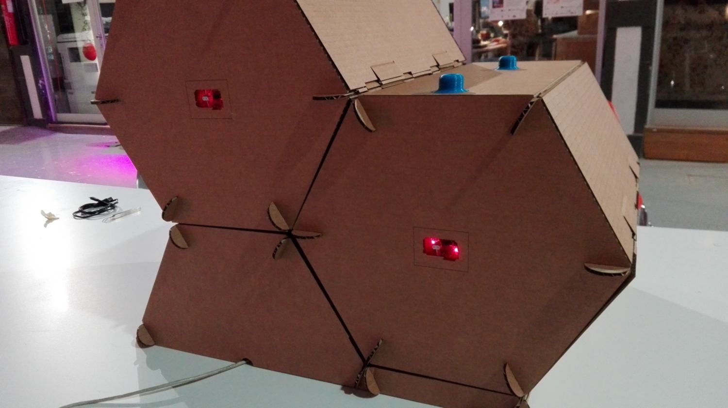
13.06.18 /I put together my final project today.
the whole setup, opened up...
...and put together.
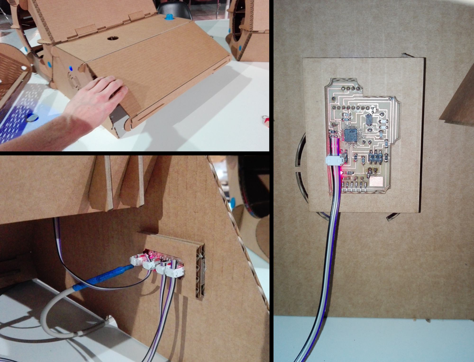
I add a cardboard casing for all PCBs. Here for the back of each casing.
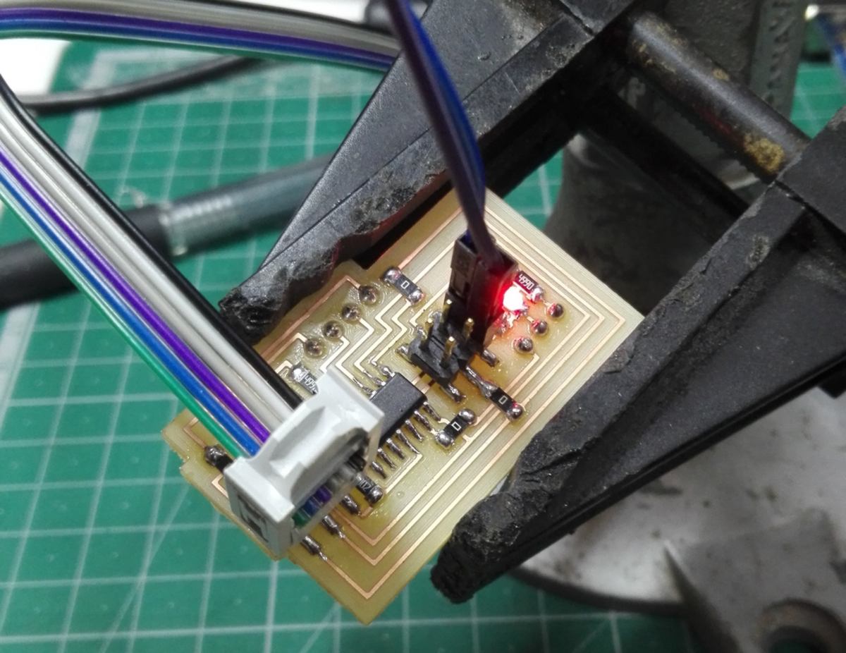
The ISP male headers are easily accessible (on the back of each casing) for reprogramming and the I2C connection can be unplugged when doing so :
In the base, the master PCB and the power/pull-up resistor for the I2C network:
A final look at the setup before testing :
I make the explanatory video (with Open shot Video Editor) and two slides (with Krita) which are at the top of this page.
14.06.18 / I populate the summary (above) with new content and attempt to write a comprehensive tutorial to replicate this design from scratch which can be found here .
15.06.18 /Now the presentation is over I take a second to reflect on what aspect of this design could be improved :
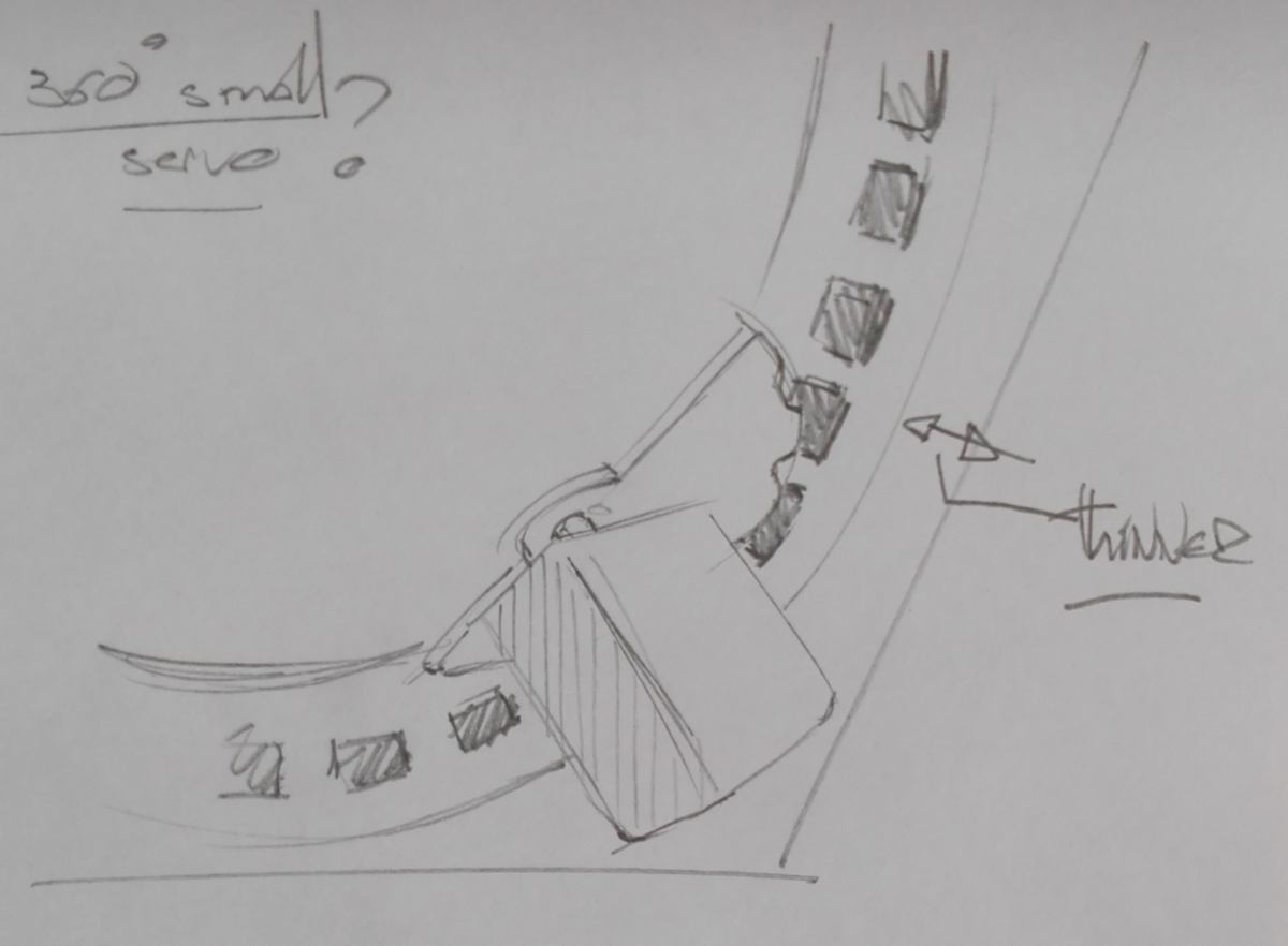
Casing
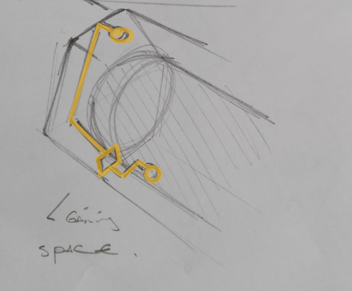
- The thickness of the casing can be diminished. To do so the the servo can be relocated in an angle of the casing. Also, the slots into which the the driving gear pushes can be cut in the middle of the actuator ring rather than the bottom :
- Following the same thinking, the PCBs could be located in a corner on the back of the casing, thus the casing length being shortened.
- Each PCB could have a shape that allows it to fit and be held into place within the inner structure of the casing .
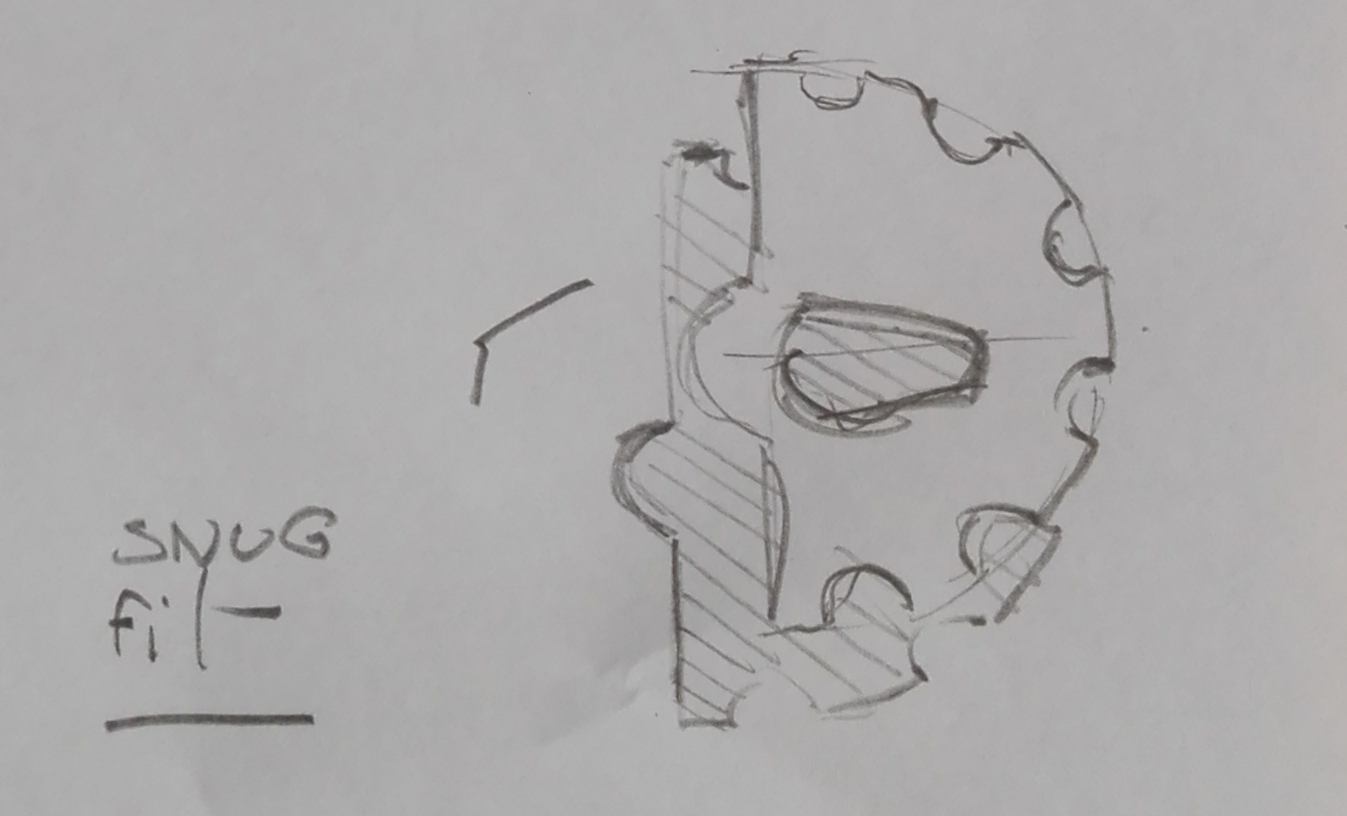
- the driving gear can be redesigned so the servo fits in, making the whole system more sturdy :
- is there servo of that size able to turn further than 180 degrees? my guess is that there is. To be looked into.
Capsule (drawer)
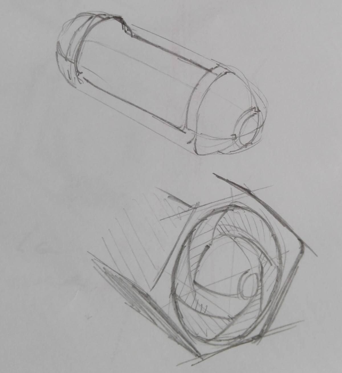
- re-design so that it looks more like a classic time-capsule AND shows rounded tips on each sides with a sample of what the capsule offers. This sample can be seen when the capsule are locked in their casing.
Other elements and consideration
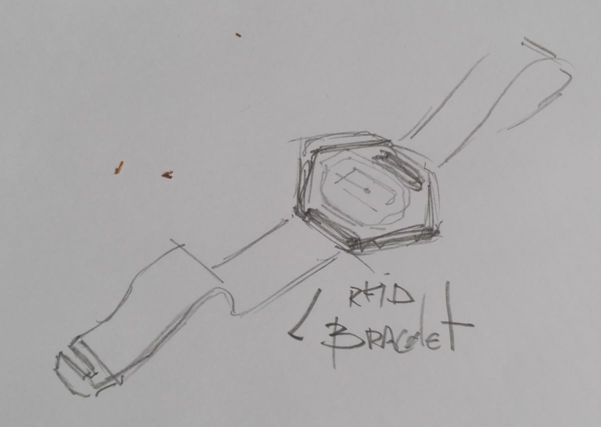
- the RFID tages can be re-designed as printed or molded shapes which can be mounted on bracelets or necklaces, and flat enough to fit in a wallet wihout making too much of a bump :
- the inner cut of the front layer which circles the actuator ring should be larger by a few millimeters, ensuring that the actuator ring will spin easily, being in contact with the bearings and the bearings only;
- All parts playing a part in the motion of the Iris ( the four structural components directly in contact with the servo, the two bottom beams and the actuator ring) could be re-cut in 4mm plywood, to ensure sturdiness over time.
This concludes my comments about my final project and its developpment during the Fab Academy.
 Fab Academy 2018
by JEAN-BAPTISTE NATALI
jbnatali@gmail.com
Fab Academy 2018
by JEAN-BAPTISTE NATALI
jbnatali@gmail.com


