Final project development
How I did Mooods
Final project
This is the last week and we finally get time to put all things together. But let’s be honest it will be a rough week.
To my point of view there are still some points I would like to have time to think about. Which input sensor to use ?
But no time to dream, let’s do some action.
This week was a electronic nightmare. The design is good enough but the execution made me debug all nights long. I did not slept a lot during this week, but at the end I was happy to have something to present.
inspiration
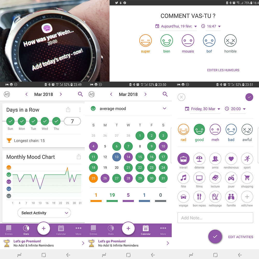
I took inspiration from a mobile application called Daylio, a micro diary application that asks you every day your mood. So you can have stats about your moods (available on Android and iOS).
The big picture
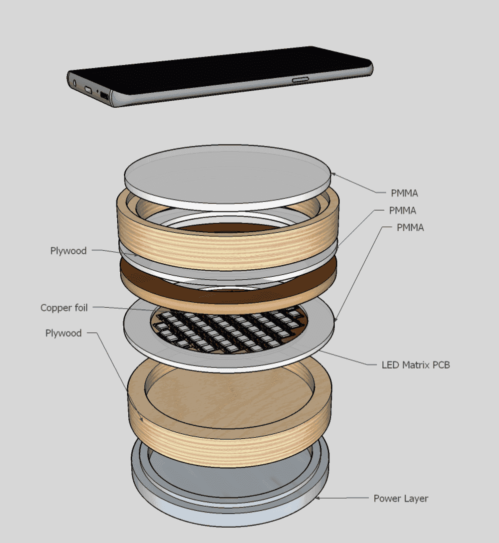
Several technics (milling, printing, casting, cutting) and several materials (wood, aluminium, plactic, resin, foam, resin, …) are used to create the moood rings.
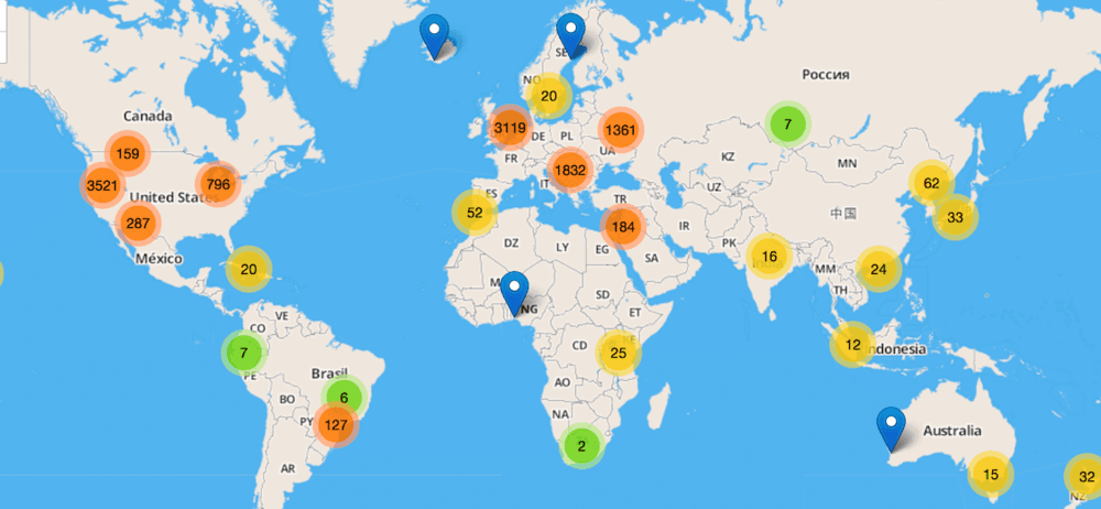
The device will use BLE (bluetooth low energy) to send the level of happiness you will choose using the input sensor, to your mobile phone. A mobile phone application will receive your data, and will add its location (longitude and latitude) to a REST web service hosted on the cloud. This web service will store data to a database. Finally a front web application will show a global map of the levels of happiness of device users.
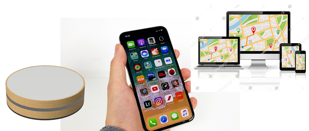
Exemple of the map that can be shown. But honostly I will not have enough time to fo this part.
Design rules
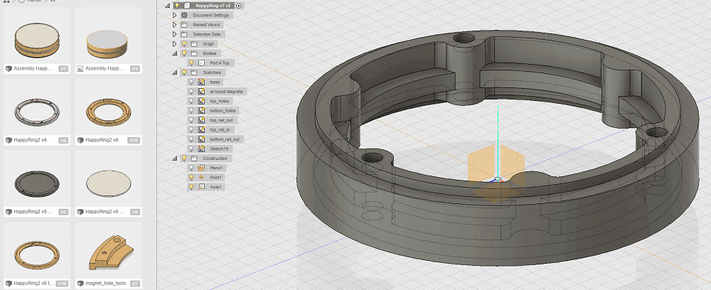
CAD - The common hardware interface
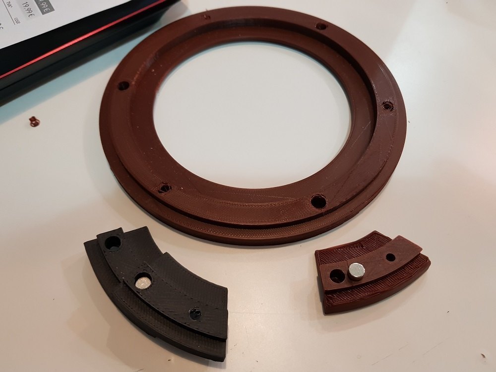
In order to create a unique design that allows us to create rings using several technics, I imagine that design using magnets to attach them all.
Doing some tests.
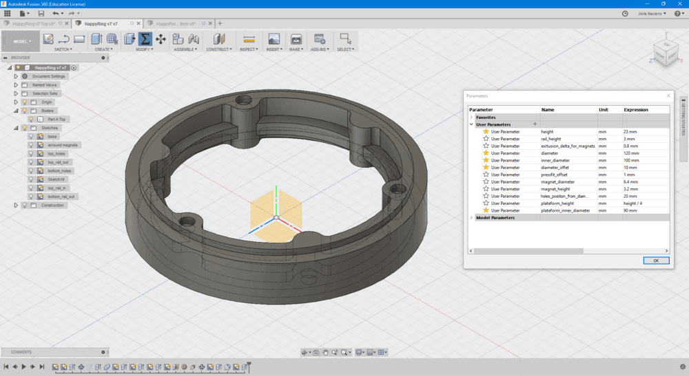
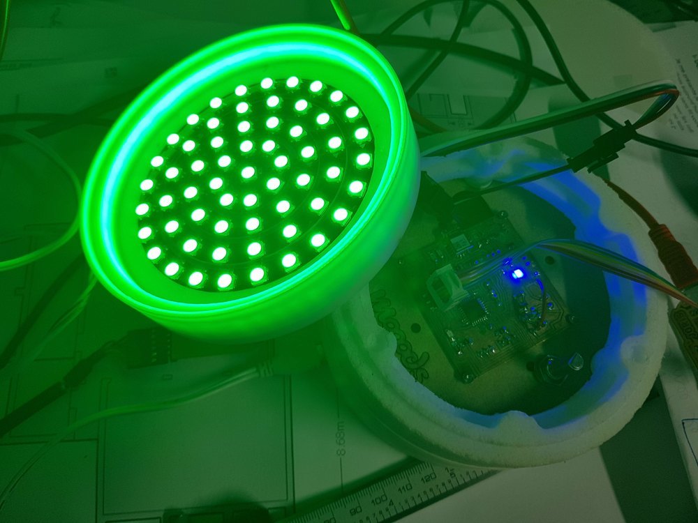
Top Moood ring
At the end, I designed 4 parts (top, regular, electronic, and bottom)
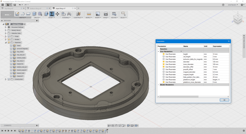
Regular moood ring
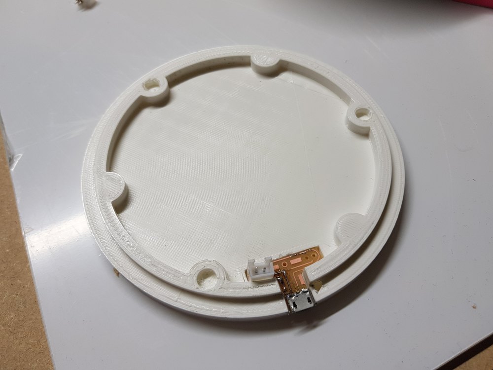
Electronic board moood ring
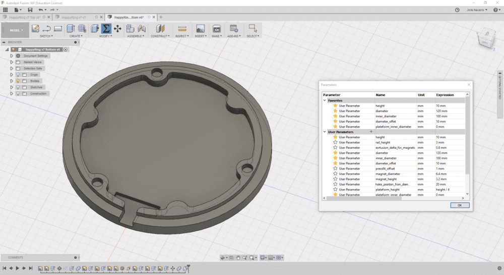
bottom moood ring
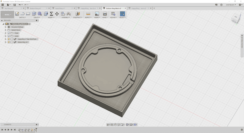
mold for regular ring
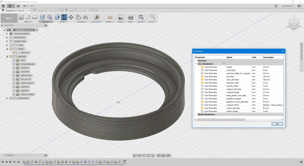
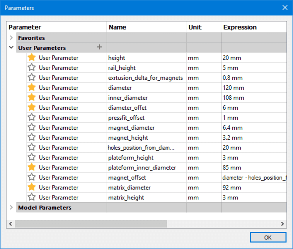
Parametric design
Fabricating
Once I already have my designs done during the semester, I also have some parts made with the assignements.
Electronic
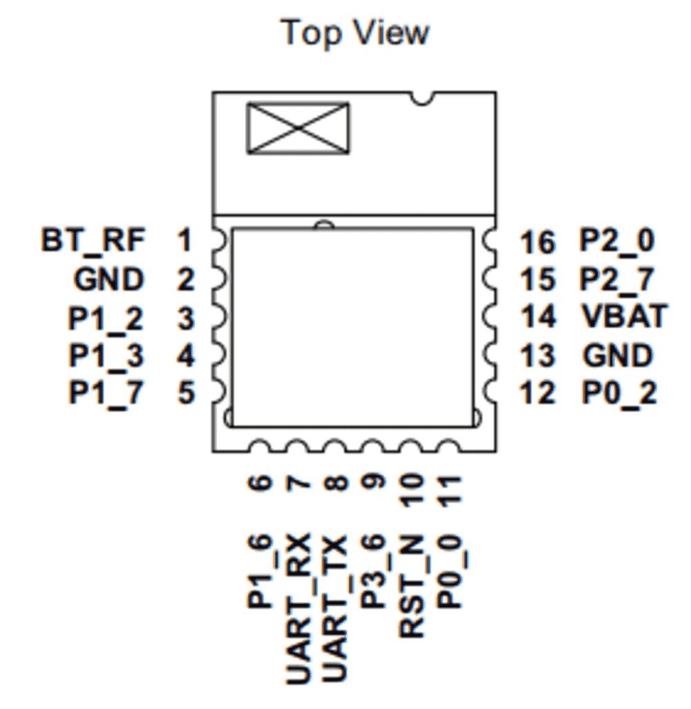
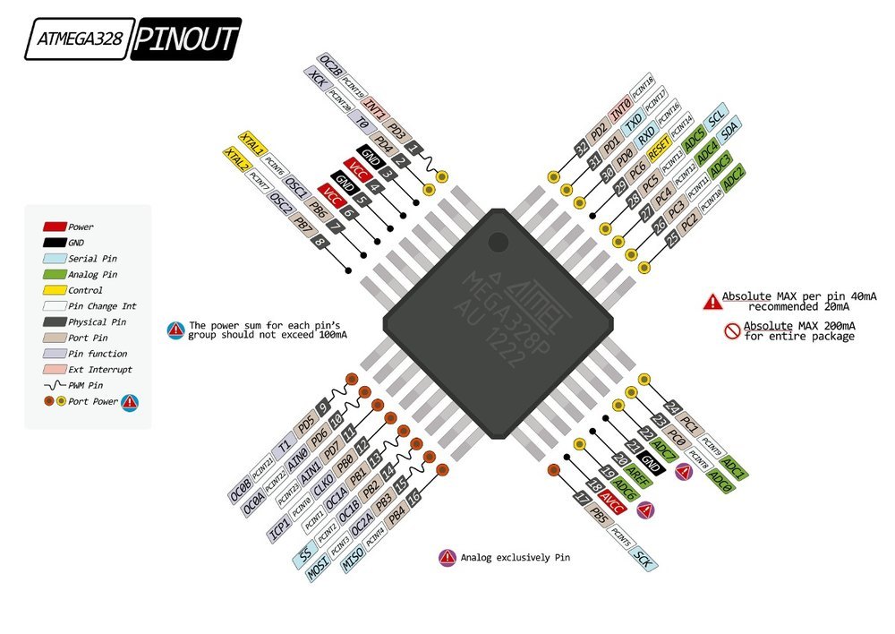
Reading Datasheets: 2 main chips were used : RN4871 BLE chip, and ATMega328p MCU
RN48711 Datasheet
ATmaga328p Datasheet
Neopixels - WS2812b datasheet
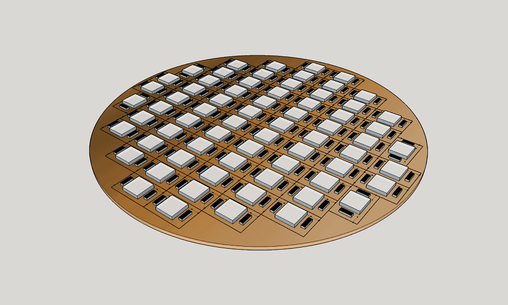
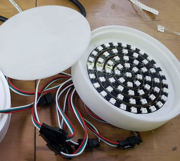
I would loved to do my LED matrix but I ran out of time and I found already made ready to use, cheap (20€) matrix
See how it works:
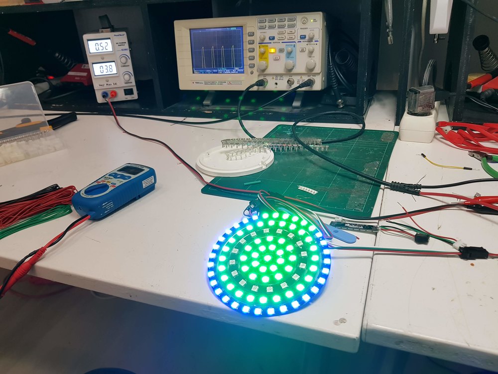
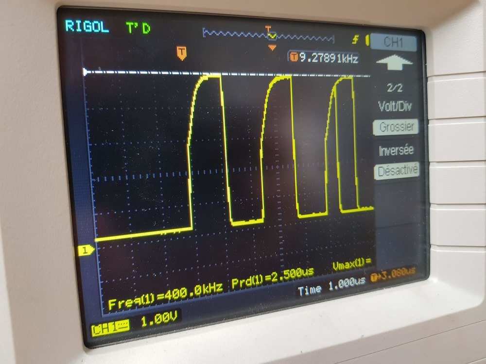
Runing default exemple code from adafruit failed. I was unable to turn on any LED. Board is powered with 5V voltage. A voltage regulator is used to power bith chips, atmega328p and RN4871, due to maximimum voltage of bluetooth chip is 3.3V. But the LED are driven using 5V that is why a mosfet based level translator. The protocol used by those LED is basec on en accurate timing, and I supposed that the level convertor system slow down and alter the signal to the LED. I tried using another ledstripe with the same result.
I read some documentation about how to drive Neopixels LED using a 3.3V MCU.
In conclusion most of people recommand using a level shifter. There are several chips that does the job: Without being expert there is so much choice I read dome datasheet of the most common ones
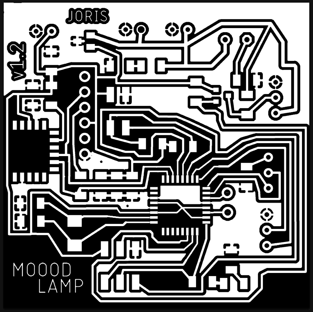
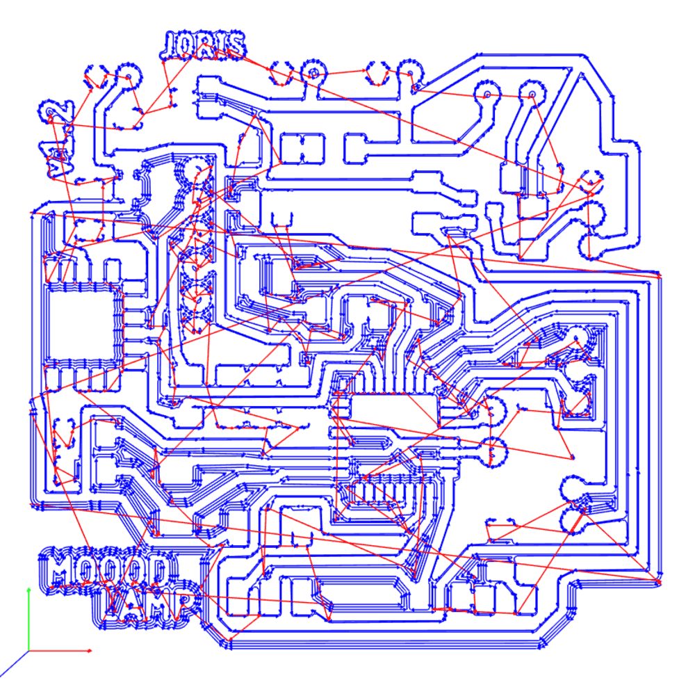
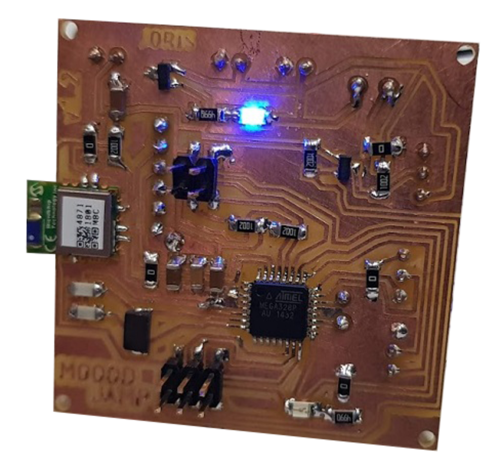
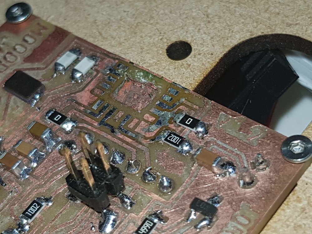
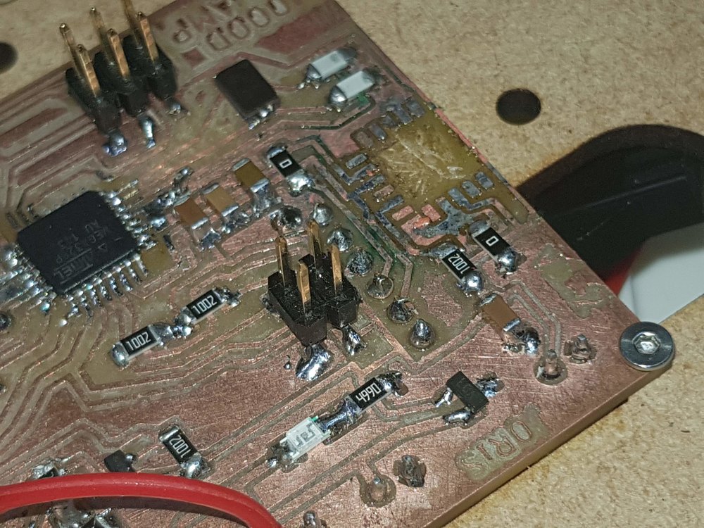
PCB Final electronic boards designs, Schematics explained
Power board
Power will come from an micro USB socket, I will use a Raspberry Pi 2.5Amps power adapter. Because according to the datasheet of WS2812b I know that each LED can consume up to 60mA (full brightness - White color), I will use 61 LED. 61*0.06A = 3.66 A. As I don’t have such a power supply I have to be carefull and set the brightness to 50%. Also I will need to be carefull of the thickess of the traces. Probably I will and and extra cable to divide the current and more solder on traces.
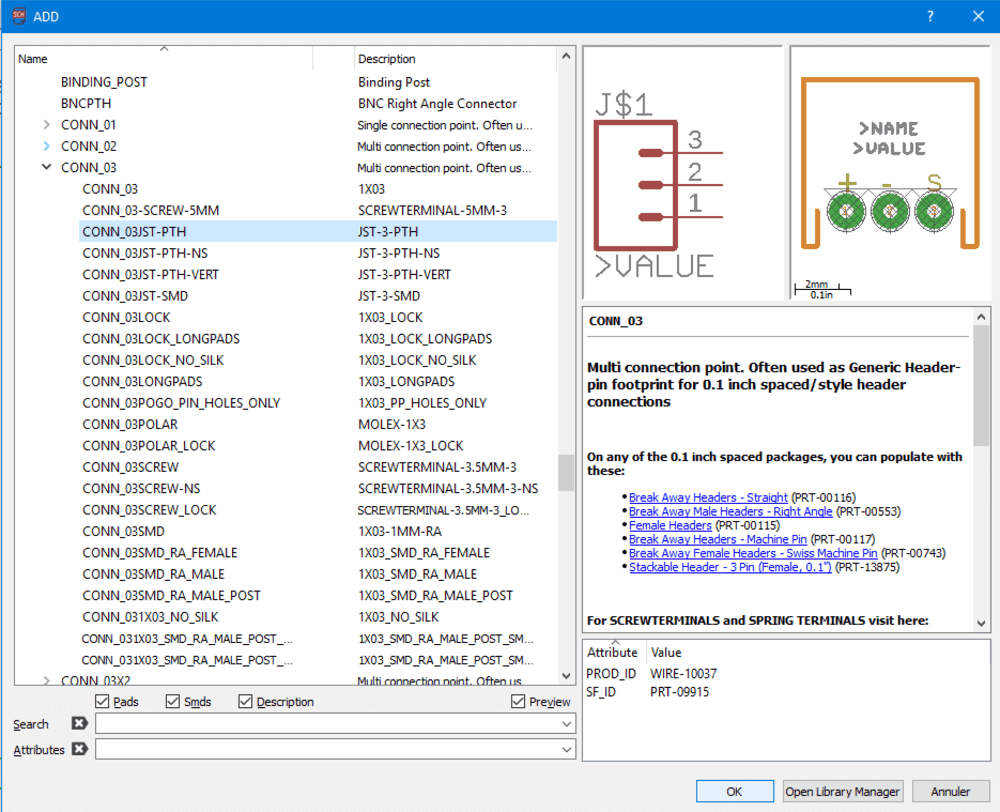
This design is for 2 JST sockets (EDIT : not a good idea !)
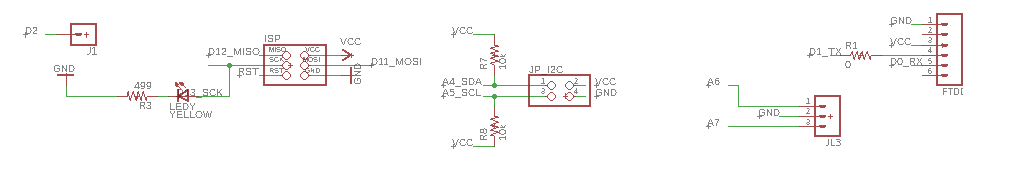
Main board
From power board : tension is 5V, here you can see the voltage regulator and a big capacitor for the LED matrix
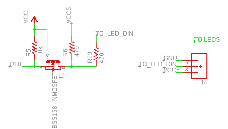
Here is the level shifter to go from 3.3V signal from MCU to 5V signal to LED matrix using N-Mosfet. And a JST socket to plug the LED matrix.
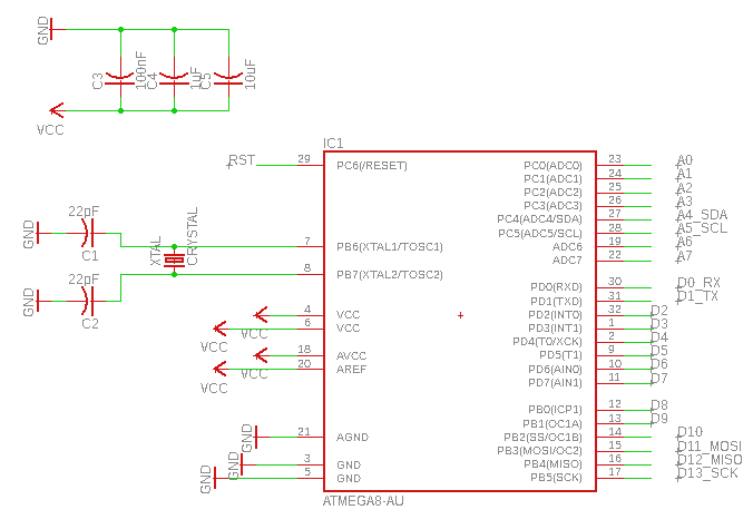
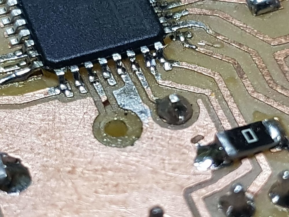
Here is the MCU original design from satshakit
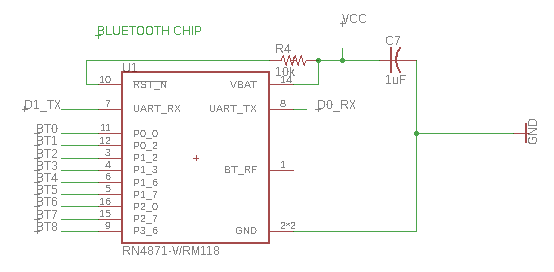
And the bluetooth chip RN4871 (VCC is 3.3V) invert RX/TX to the MCU
Extra connections: ISP to program using FabISP, FTDI for serial debugging
currently not used : I²C for extensibility , D2 pin for interrupt, A6, A7 for extra sensors
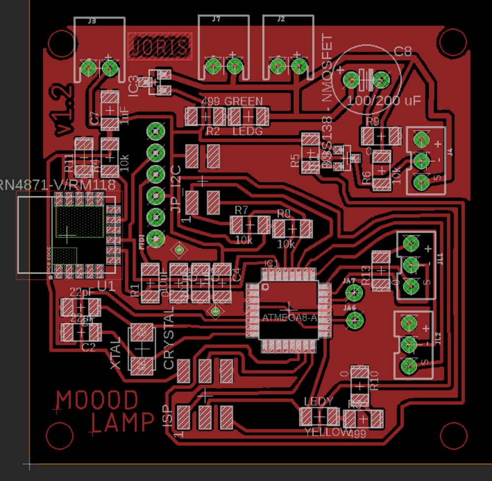
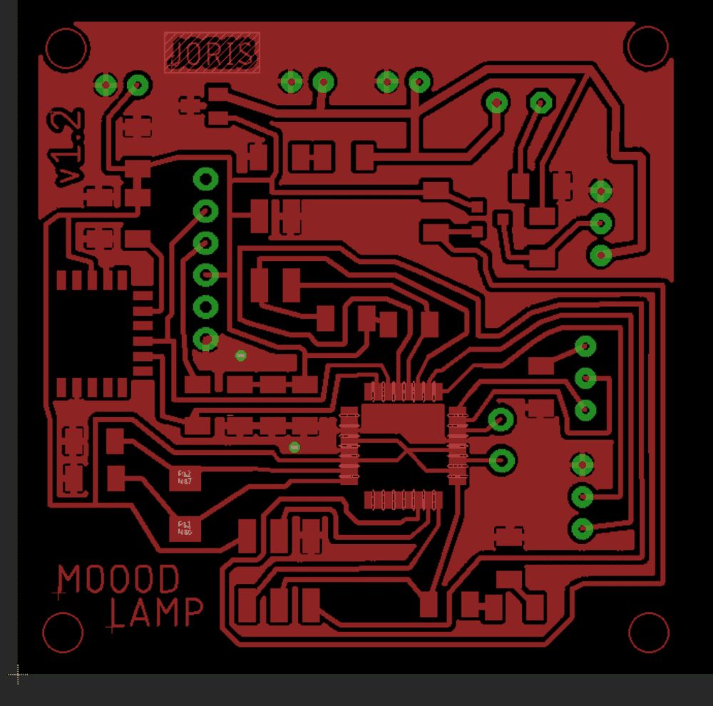
Finally here is the result in the board designer
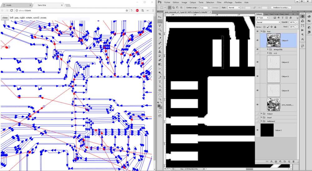
Photoshop
Mods
Did you see that missing hole ?
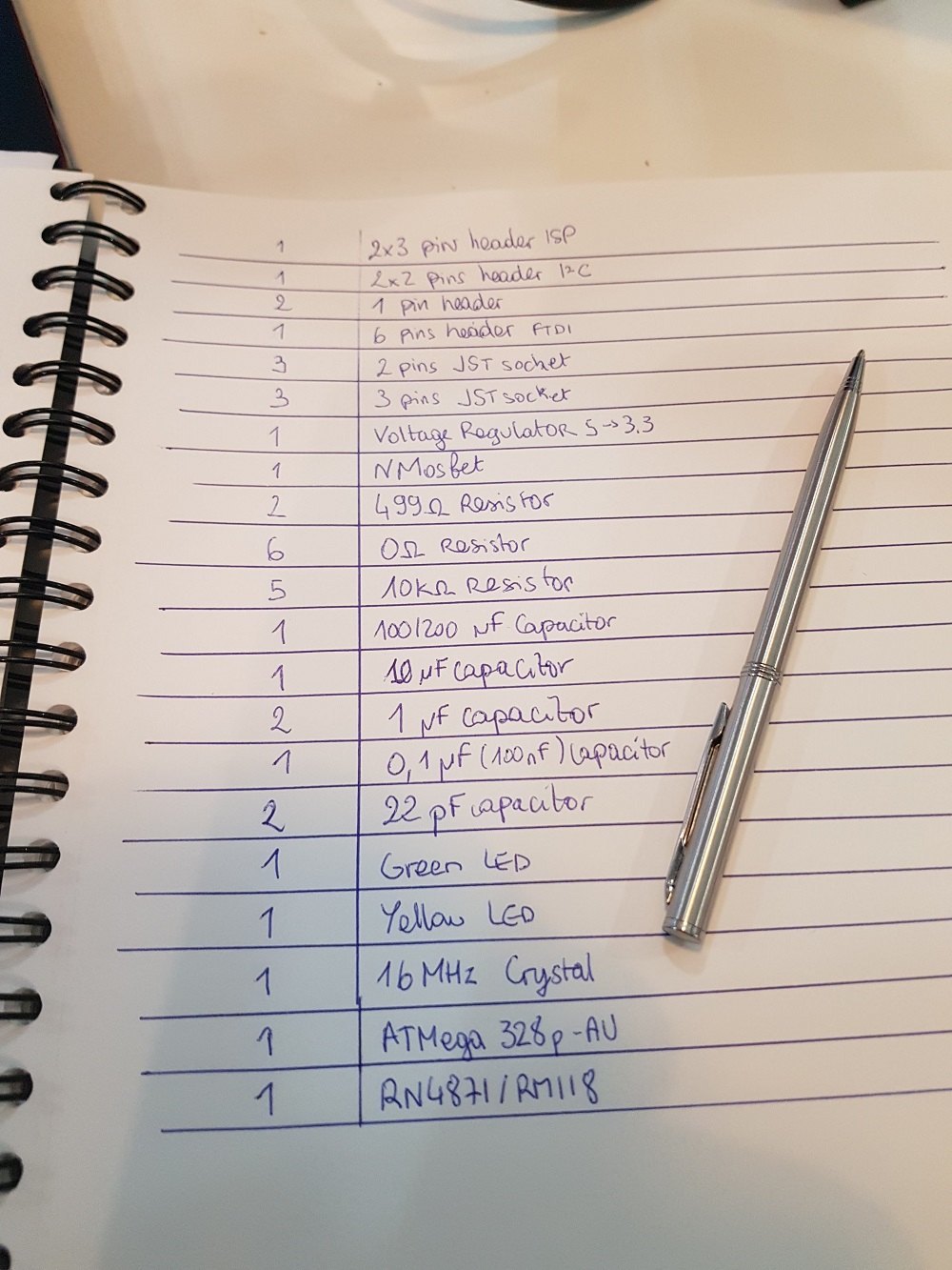
Bills of material
Go to assignement to see the BOM
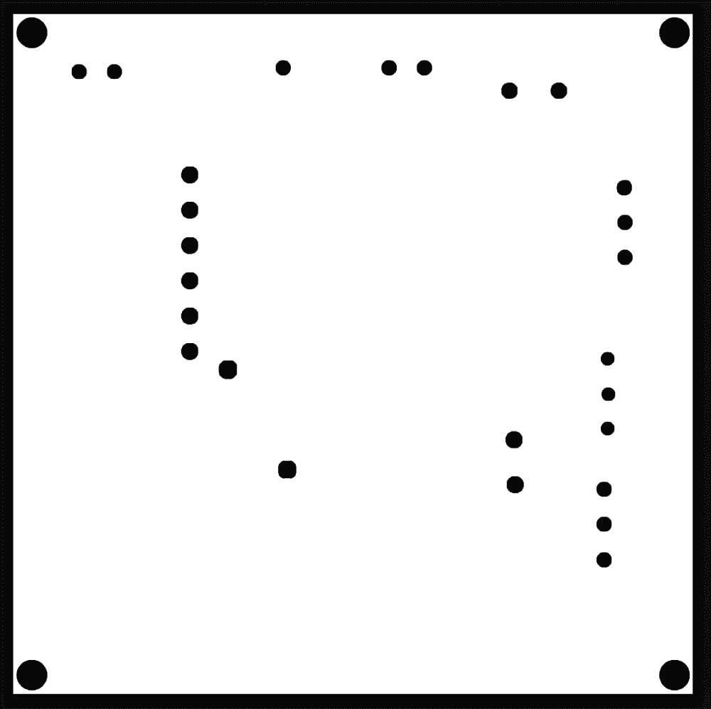
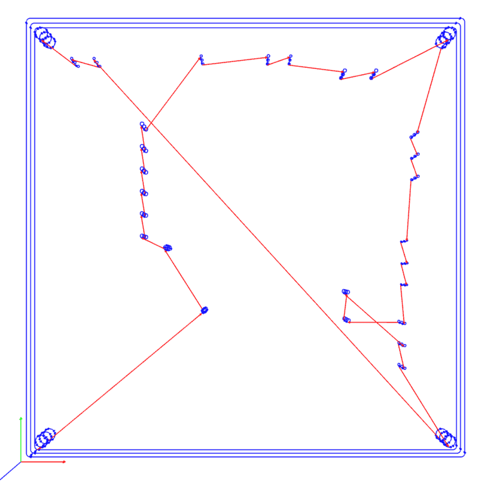
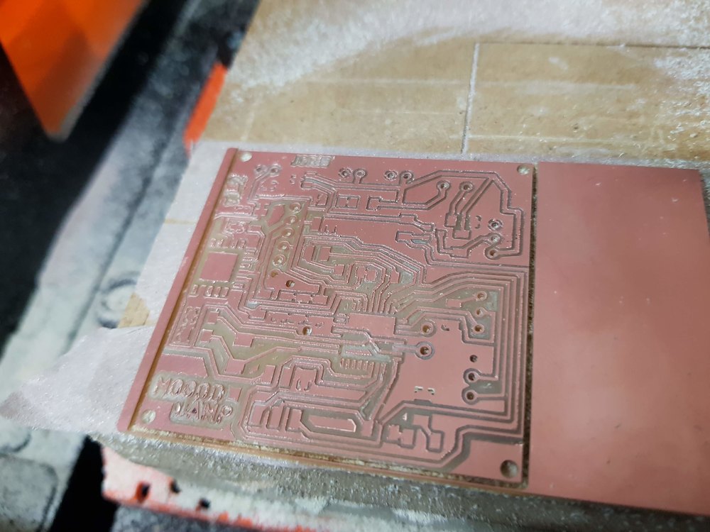
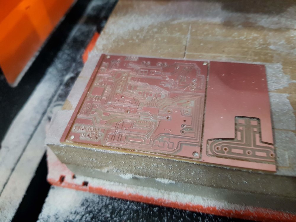
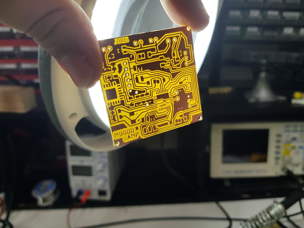
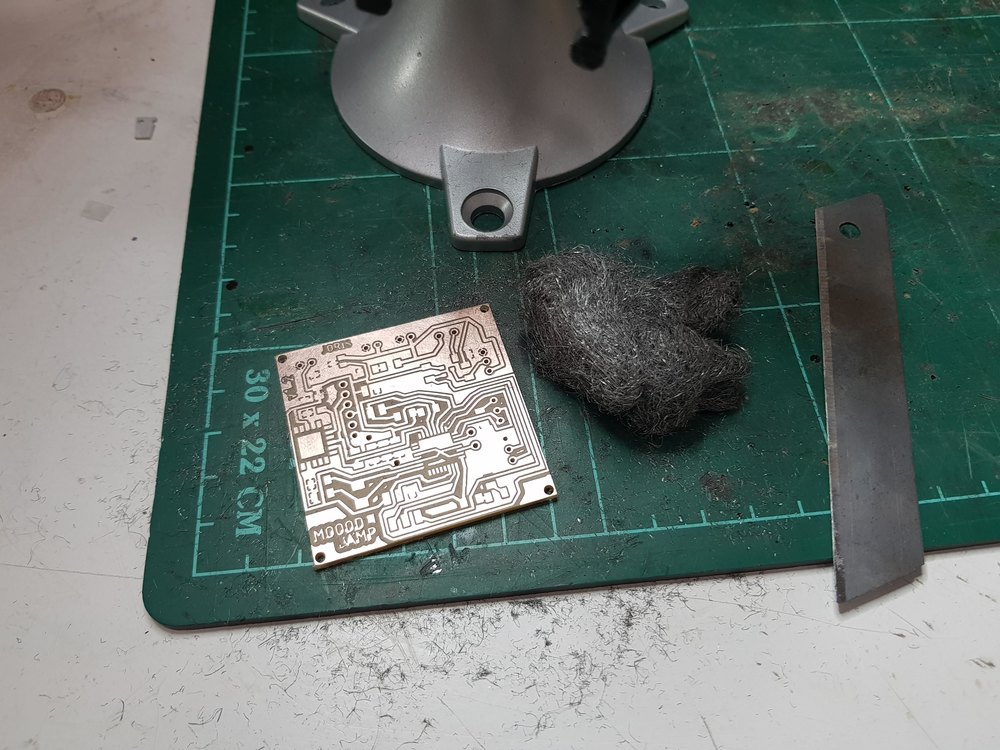
Milling
Soldering
Testing
Failures
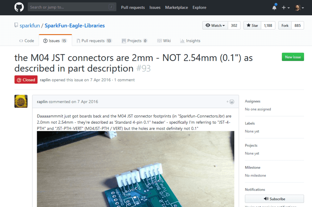
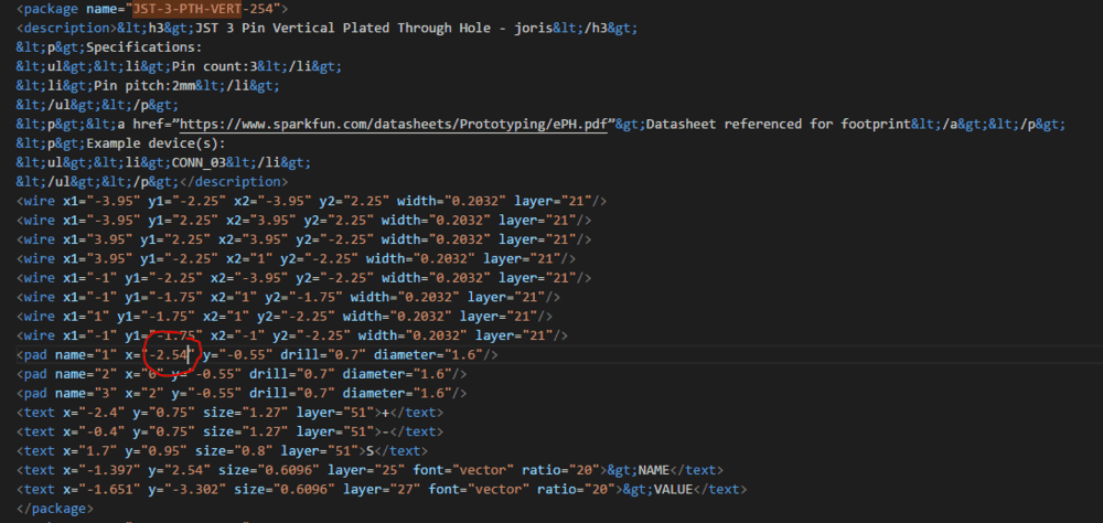
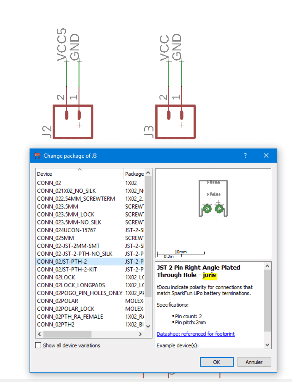
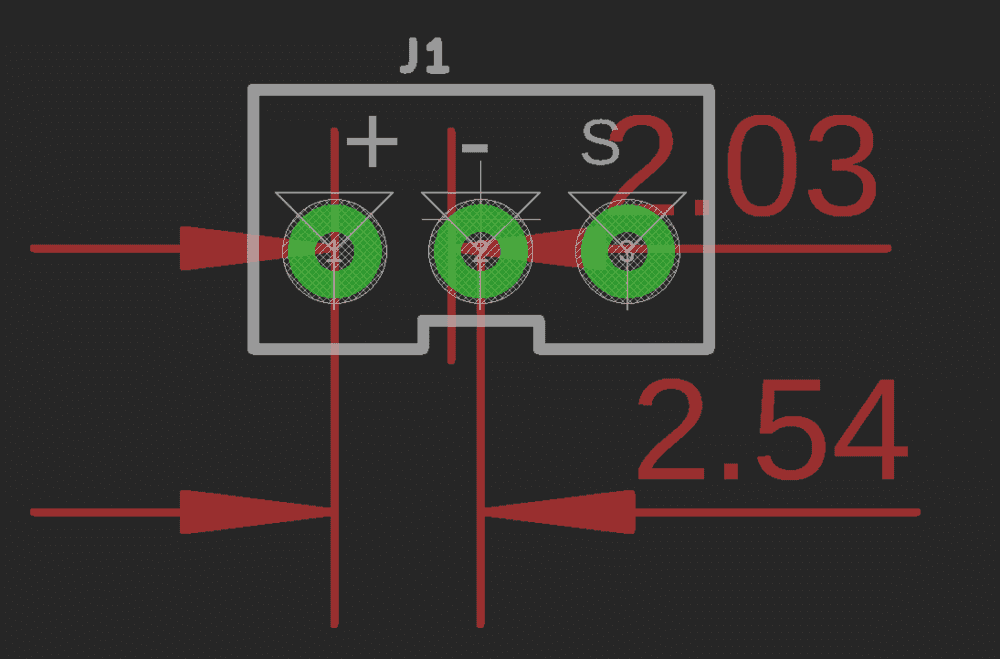
Fail 1 : component pin pitch
First milling reveal an issue with JSP components. Even If I checked (because it happened before with others components) the pin pitch between holes description talked about 0.1inch but in reality it was 2mm (instead of 2.54mm). Finally I changed the footprint on the library in order to have a 2.54mm steo.
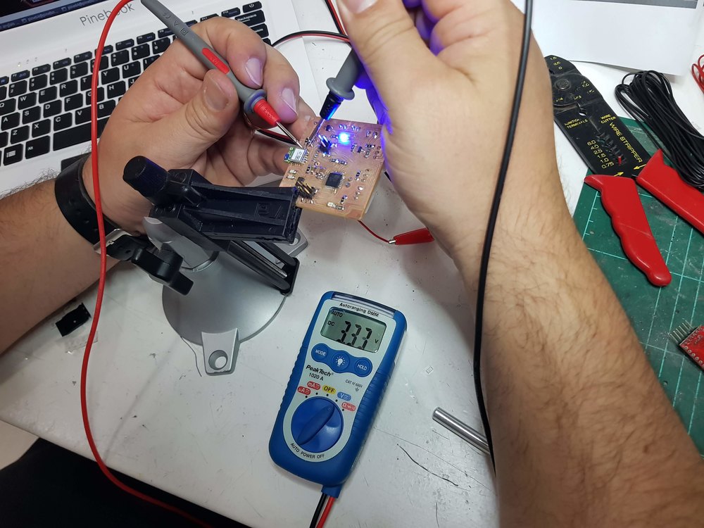
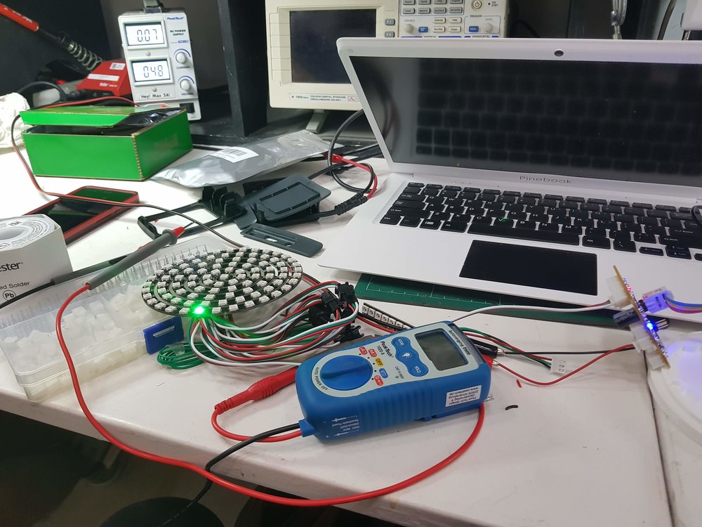
Isssues with level shifting (oscillo)
I spent half a day (at least) trying to understand why when I set power generator to 5V, the LED did not turn on, but if I changed the generator to 4.8V LED started turning on.
An ugly solution I tried was to set some resistor to decrease the 5V general voltage, but come on, this not a solution.
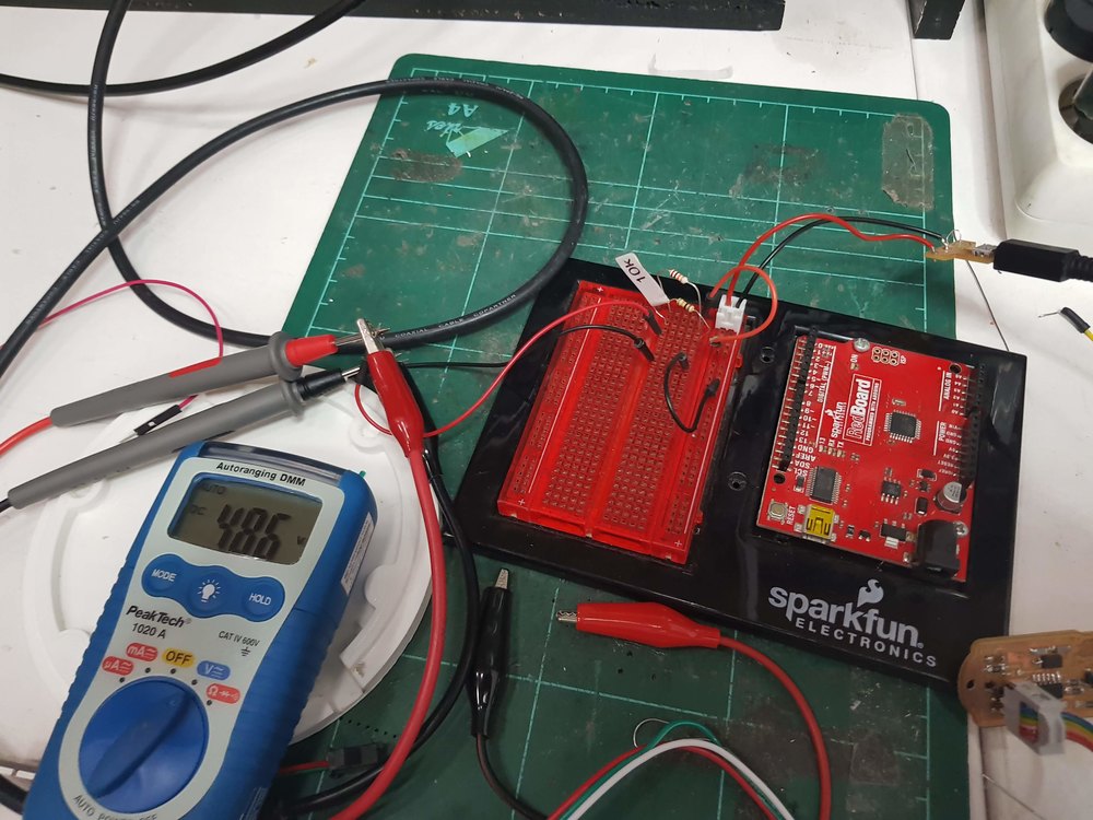
I the end I discovered that the issue came from the level shifter:
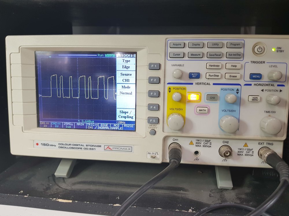
As you can see on the oscillo the level shifting did not works well. we can see 3.3V instead of 5V signal (1V per div). Then I changed one resistor to 500 ohms instead of 10k. As I did not have 500ohm (470 or 499) smd resistor under the hand I found dome 2kOhm resistors. So I stack them to reduce the global resistance value (4*2ko => 500o)
Issues with sockets
At some point, traces were brocken because of pluging unpluging.
I spent a lot of time doing cables.
Each time I plugged or unplugged thoses sockets I felt the board getting close to the trash bin. I mean I broke so many traces, those little rifts you cannot see. This drived me crazy.
2 pins of MCU are conneted, and this is not a feature!!
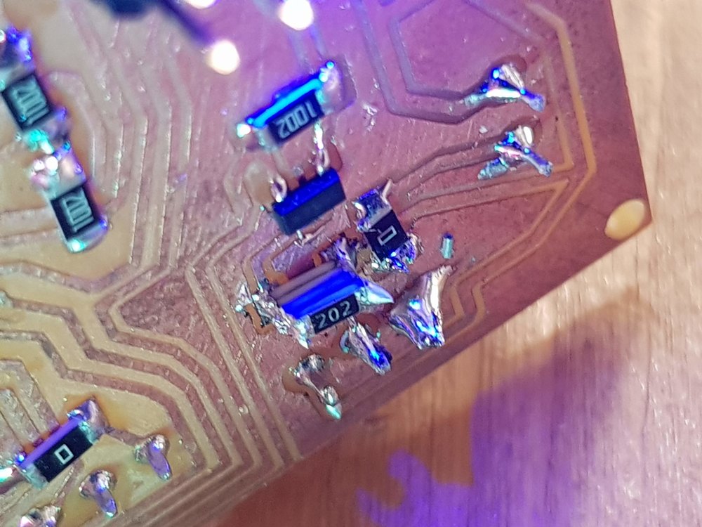
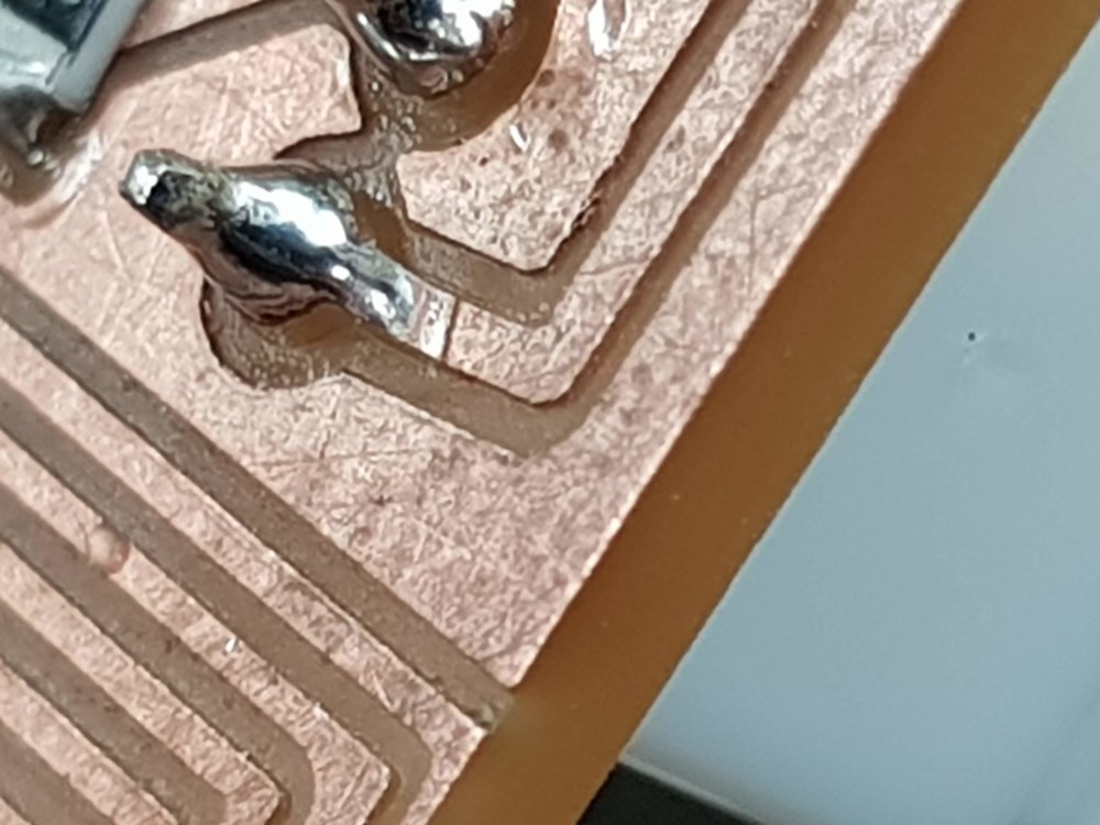
Issues with bluetooth
because of the copper left under the BLE chip, it was not working correctly. So I had to unsolder it to remove this little piece of copper.
Soldering, unsoldering the guy made me crazy, I finally broke 2 of them, because I did not have solder gun to unsolder it.
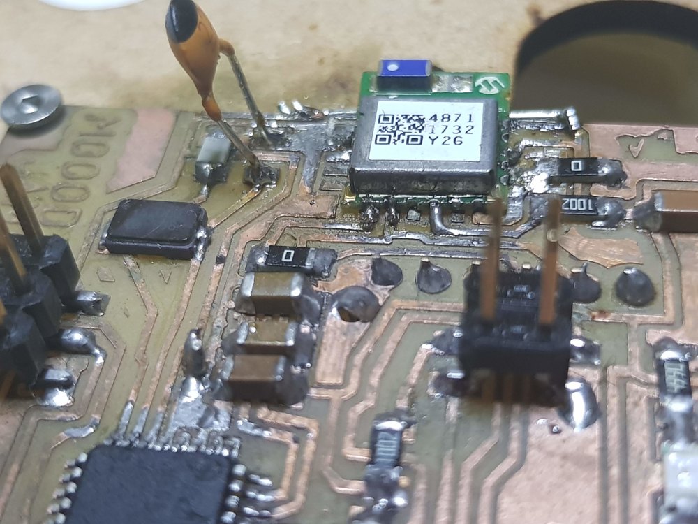
Here was a real carnage. Maybe you notice on this picture that the chip is (wrong) soldered with an offset. on the third (from the left) pin (not soldered here) that is the TX pin the copper is gone, at the end this chip is not usable anymore.
Maybe you also notice the big capcitor at the left of the chip. because a 22pF died and I did not have a 22p smd I put a big one ! but it worked.
3D Printing
During the 3D printing assignement, I started testing, making some rings
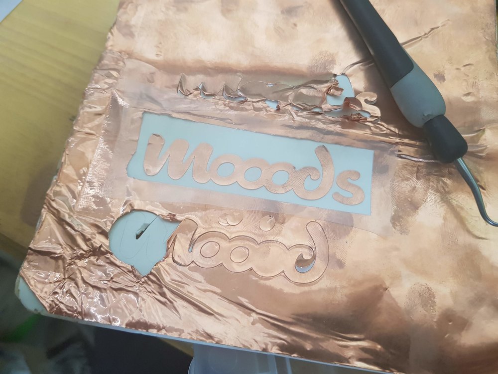
Vinyle plotter (for the deco)
Using the design made for the cutting assignement, I made a copper sign, that could be used as a new button.
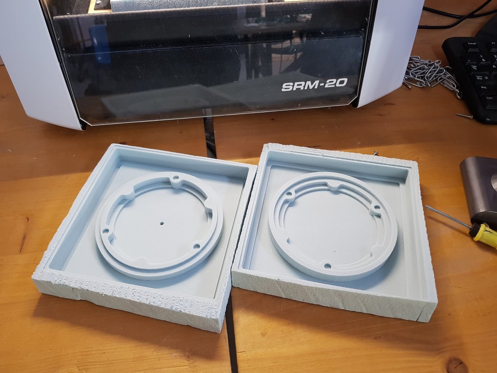
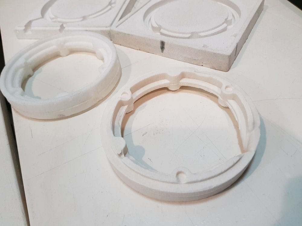
CNC Milling
During CNC machining assignement I started testing and making rings
.jpg)
The last week I milled the top ring using 30mm PMMA
Molding and casting
During the molding and casting assignement I started testing and making rings
Laser cutting
Laser cutting technic has been used for 2 purposes
- laser cut rings
Bottom ring in black PMMA and MDF
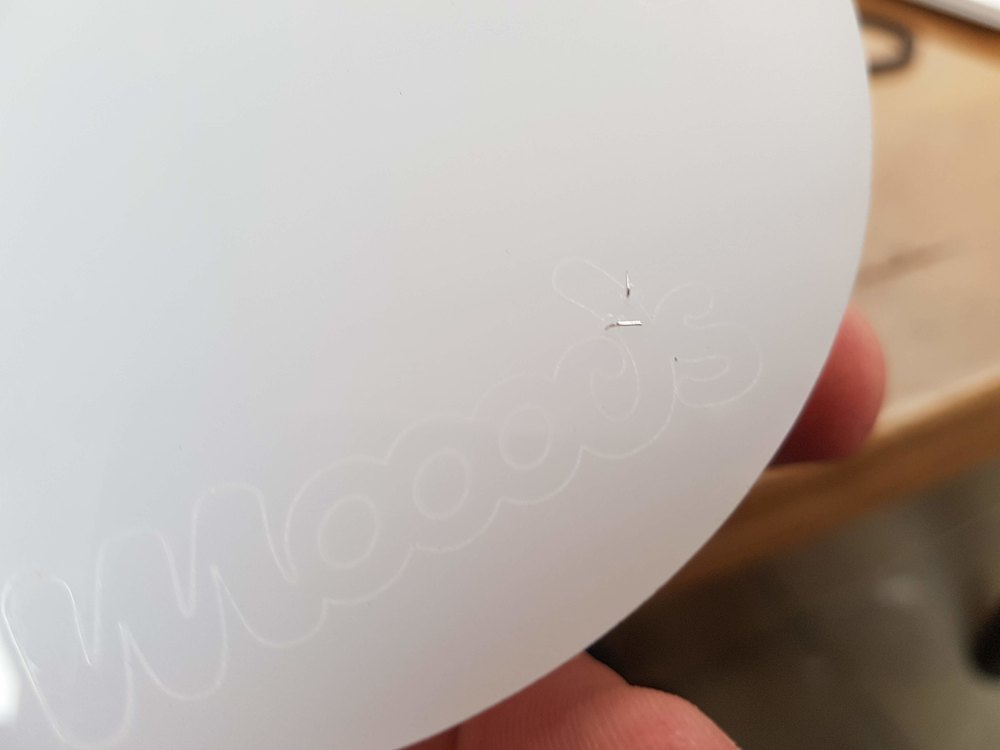
- engrave PMMA for capacitive sensor
Input sensors
As you can see on the previous picture I engraved PMMA and used the laser to make small holes to put some thin wires.
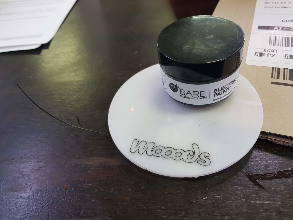
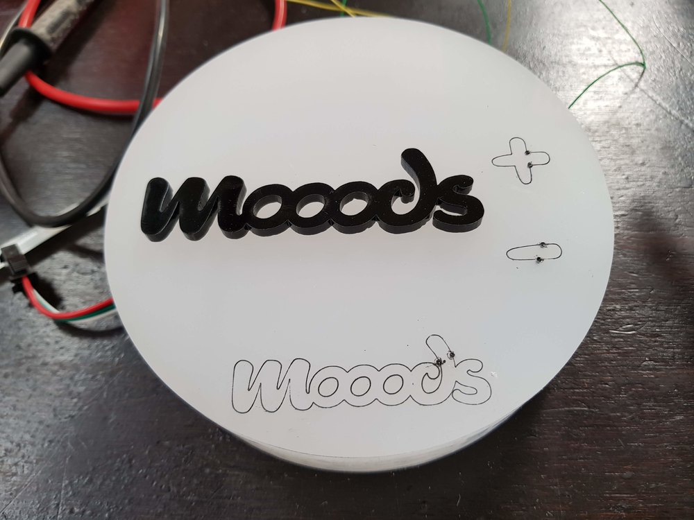
Those wires are connected to the board using 10MOhm resistors as explained in this video
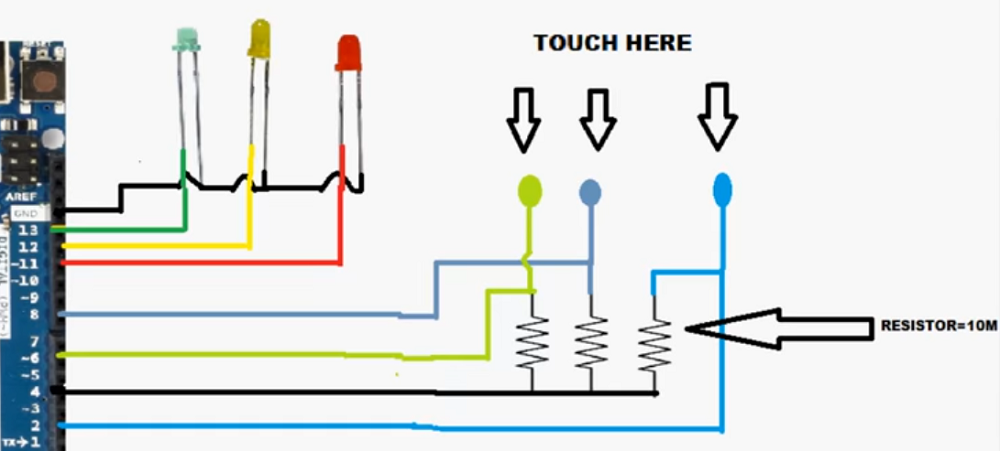
I used the mentionned Capacitive sense library created by Paul Badger
Sample code from final project
#include <CapacitiveSensor.h>

CapacitiveSensor cs_mooods = CapacitiveSensor(A3, A2);

void setup() {
  cs_mooods.set_CS_AutocaL_Millis(0xFFFFFFFF); // tuen off re-calibration
}

void loop(){
  long cs = cs_mooods.capacitiveSensor(80);

  if (csSum >= MAX_TRIGGER)
  {
    // sensor has been touch

    // do your stuff here, like turn on LED, serial ...

    cs_mooods.reset_CS_AutoCal(); // sot readings
  }
}
Output
Using neopixels library created by Adafruit
Coding
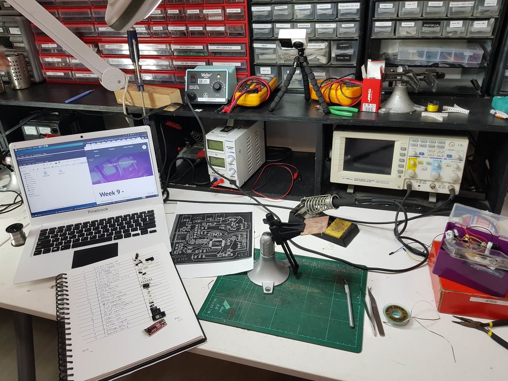
Setting up cding environement
I used Visual Studio 2017 with the free Visual Micro Plugin to write and deploy “arduino” (I mean using AVR toolchain) code.
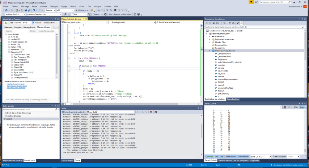
For understanding the code, all you have to get is the state machine. Using a gloabl var called mode I know in wich mode I am (idle, regular lamp, happiness level, uploading).
Once sensors calibrated, I use them as buttons.
Communication
Communication used is the one studied during the Network and communication assignement.
Using NRFConnect on the mobile phone let me see the current values read from the sensors and written to the serial
Server side (Still in progress - out of FabAcademy scope)
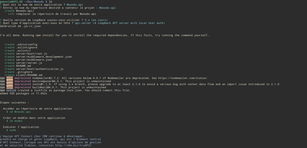
I, with a little help from my frien Gwenole who works in my fablab, used Node.js, a javascript framework to write some server side code. I build the service on top of a node:8.10-alpine docker image. For the database I use mongodb.
here is a screenshot of the docker-compose.yml used to deploy the app.

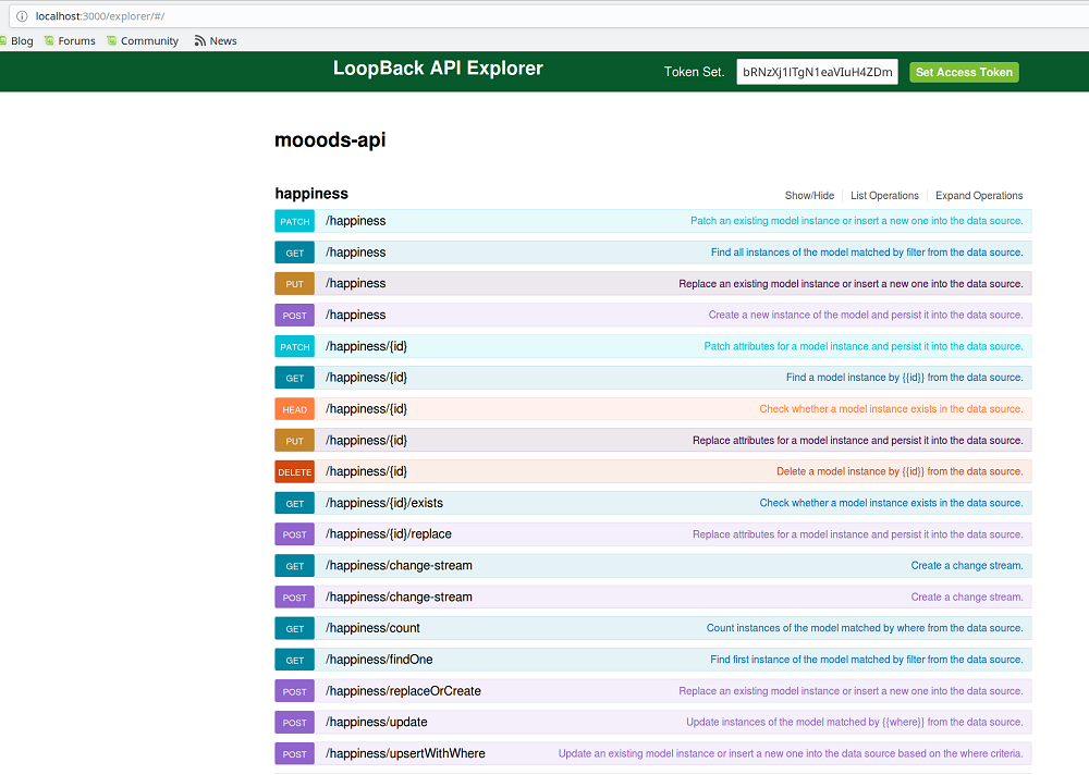
I used a tool called LoopBack to generate the REST API.
Creating app models
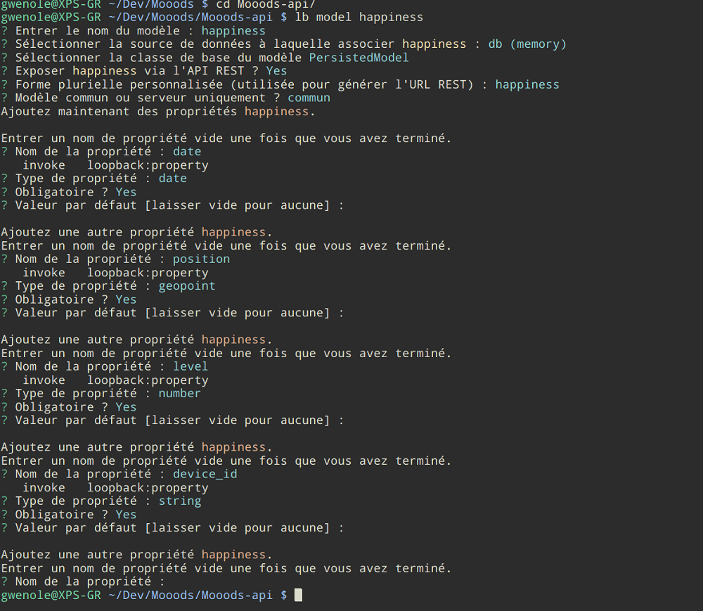
Creating server API
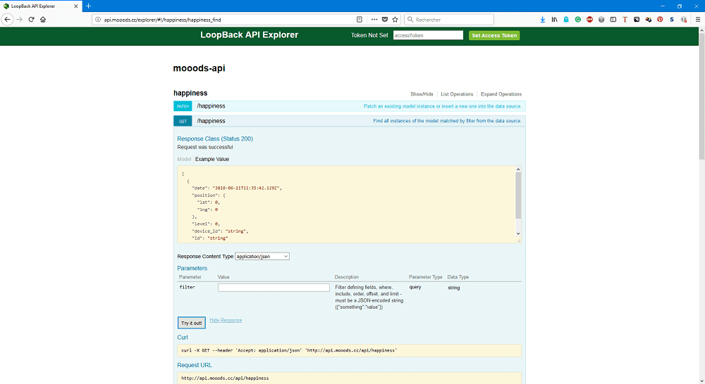
Testing generated API locally
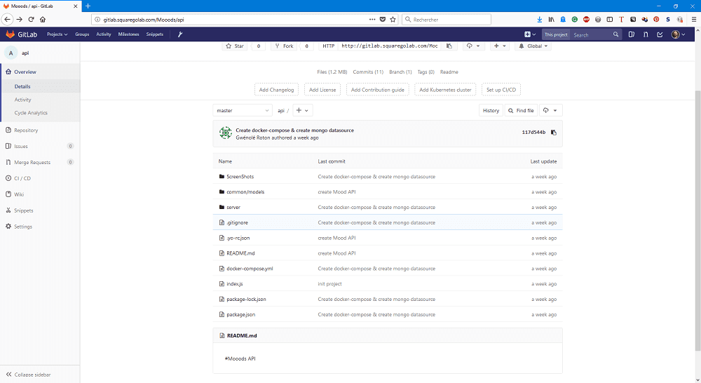
Screenshot of the repository where the sources code are:
We deployed that container on our server : .
Mobile application (Still in progress - out of FabAcademy scope)
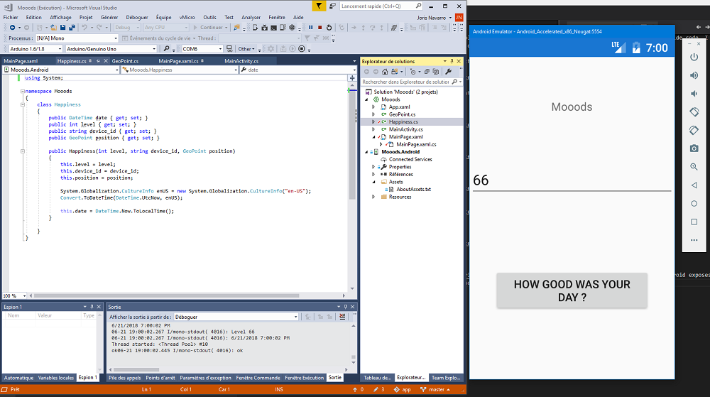
We used Xamarin.Android to developp a first mobile application. Xamarin.Android exposes the complete Android SDK for .NET developers. Build fully native Android apps using C#.
You can run the mobile application using Android Simulator or on your phone using Live Preview.
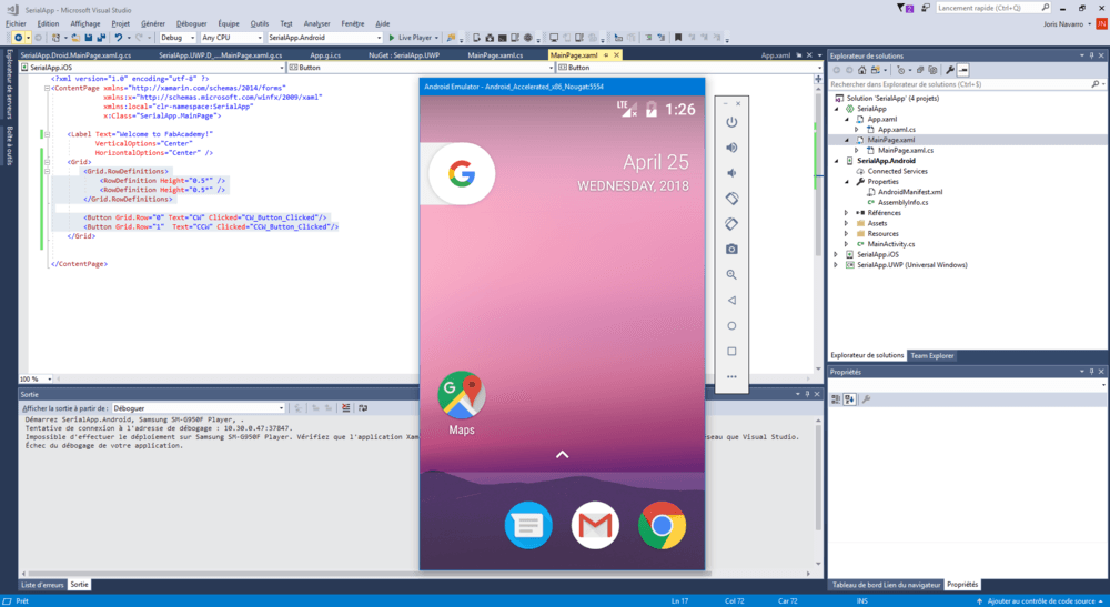
Here is a screenshot of the current “testing” mobile application that communicates with the REST API
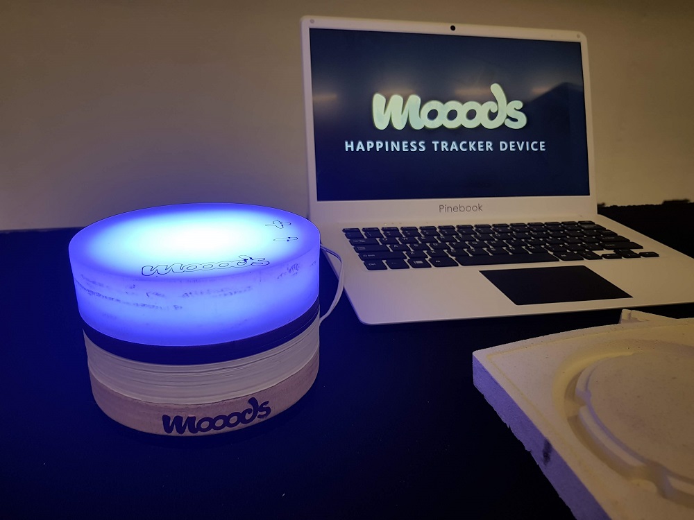
Hero shots

Want to see it live. Let’s meet in Toulouse for FAB14 !
Files to download and source codes
Everything is under CC BY licence:
- Mooods logo (inkscape)
- Moood Lamp :
- Electonics designs (eagle files)
- milling files (eagle exports + photoshop)
- CAD/rings - 3D models (fusion 360) - 2D sketchs (rhino + DXF)
- embedded programming code (visual studio or arduino IDE)
For others projects sources (out of fabacademy scope), they are hosted on squaregolab fablab perpignan gitlab. To access those repository you might need to create a local account:
- Moood Mobile App : mobile application
- Moood Server : REST API service
- Moood Front app : Web App to display hapiness (not started)
- Moood Web site : Web site presenting Mooods Sources - website
Stay in touch
Hi, I'm
Joris Navarro, from Perpignan (France), a proud dad, a fab director/manager, a teacher, a ceo, a FabAcademy student, but not only. Click here to know more about me.
Check my work for FabAcademy on FabCloud GitLab
@joris.navarro.
Want to say Hi ? Please send me a message.