3D Scanning and Printing
Week 6 - 3D Scanning and Printing
Here you will find my work description during this fifth week
General info
Class notes
Assignment
Our assignment for this week is:
Group Assignment:
- Test the design rules for your printer(s) (group project)
Individual Assignement:
- Design and 3D print an object (small, few cm) that could not be made subtractively
- 3D scan an object (and optionally print it)
Group Assignement
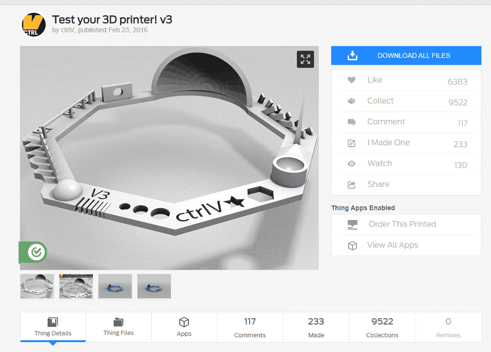
As I was not in the lab this week I could not participate to the group assignement. But I printed some test model from thingiverse to compare efficiency of 2 printers we own.
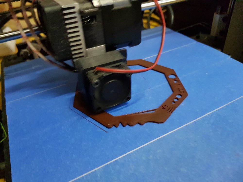
As you can see the gray one has better quality, but both of them wraped.
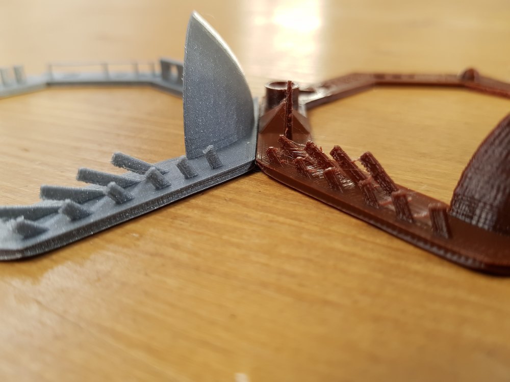
What I learn is that I have to calibrite them better. Probably to slown down the printing speed. I kwnow they could work well if your take time to tune them finely.
I am feeling pretty confortable with 3D printers while we own 9 of them, event a Roland ARM-10 for SLA printing. Most are machine you have to set up by your own.
Individual Assignement
What is 3D Printing ?
Additive Manufacturing is the sensational sounding name of 3D Printing process. From nothing to a piece just by adding several layer of materials.
There is a lot of technics, but the one we commonly use is called FDM for Fused Deposition Modeling, the principle is basicaly to melt the material that will become harder (enough to support other layers) with ambiant temperature. With “basic 3D printers” we usually use PLA or ABS, but we can use a large set of meterial depending on capabilities of your machine (Nylon, POM, HDPE, PVA, PETT, ceramic, concrete, metal, ceramic, …) without counting the mixed filaments (with carbon, wood, caoutchou, conductive, food compliant, …).
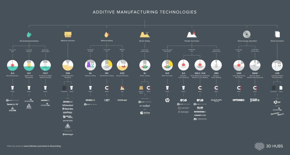
This FDM process is probably the most affordable 3D printing process, but there are lot of them you can discover. For exemple this a is an infography from 3DHubs
But why 3D printing ?
Basically because you can do some part we could “not” do using tradional manifacturing process (cutting, marking, engraving, drilling, ablation, welding, marking, turning, milling, casting, injection molding, …). That’s why nowadays 3D printing is really convenient for rapid prototyping. but not for production. Even if the process evolves every monthes with new materials, new usages, new machines we are not able to consider 3D printing as a mass production tool. But a really good prototyping one.
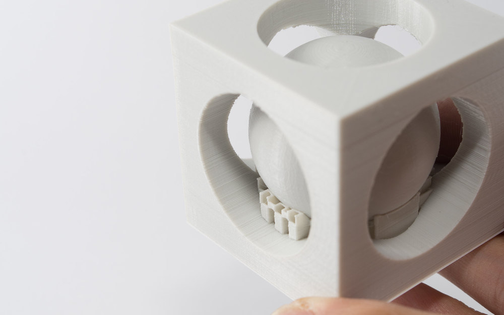
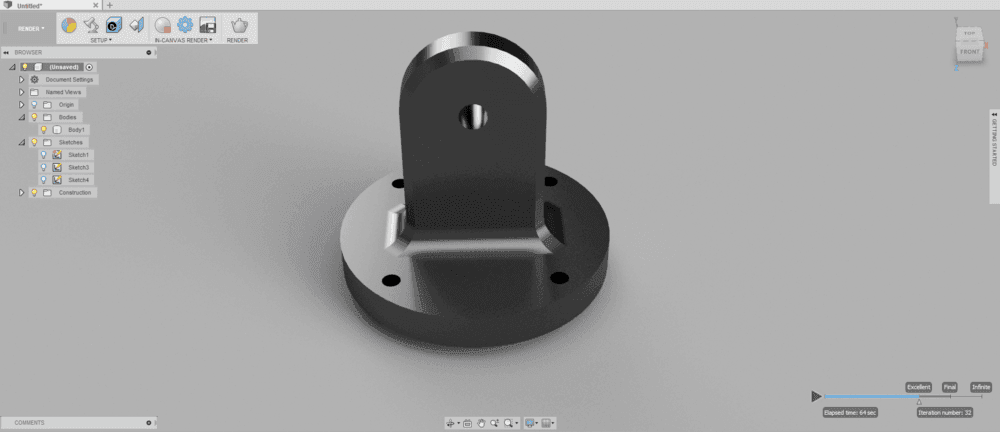
Let’s take for exemple this part, actually I cannot guess how we could do it withour 3D Printing.
Want to know more about 3D printing and other associated manufacturing processes, you can visit this “complete” documentation.
3D Printing, Pros and Cons
Pros
- Cheap / affordable
- Easy to run
- Highly customizable
- Can make some parts quite quikly
- Can do complex objects
- Not dangerous (But be carefully according to Health, Safety & Environment Department)
- Reliability
Cons
- No multi materials
- Not convenient for production
- Toughness
- Limited meterials
For this assignment
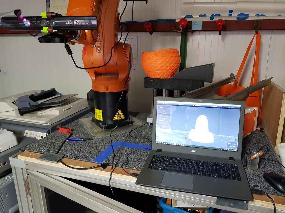
I found here a perfect occasion to make a scanning project I would do for a long time. The goal is to use our 6 axis robot arm to hold a kinect to scan people.
What we need :
- A 3D scan turntable (that can cary people)
- A kinect v1
- Scanect (optionnaly Pro version for better resolution)
- 6 axis robot arm
- A kinect to robot adaptor
We already have a kinect and Skanect Pro.
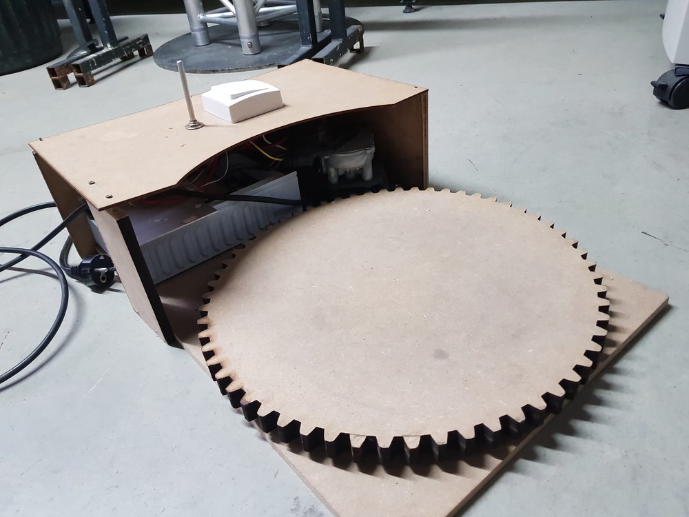
We made a few years ago a turn table with a lazy susan and a wiper motor.
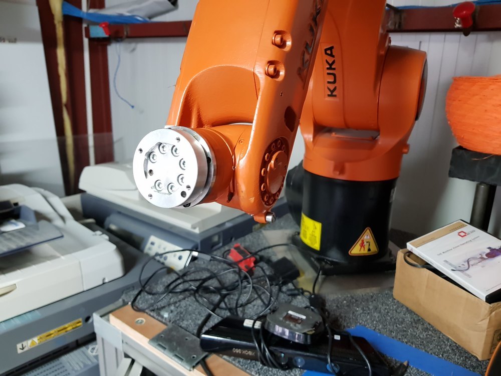
We have a Kuka KRC4 R900 as an educational robotic plateform.
3D Printing
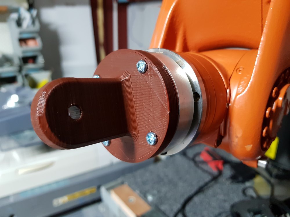
In order to let the robot hold the kinect sensor we have to design a custom kinect to kuka adapter.
I went on internet to check if this part hasn’t been design by someone else, and found on thingiverse an interresting 3D printed design: Even Erichsen’ kinect Grip
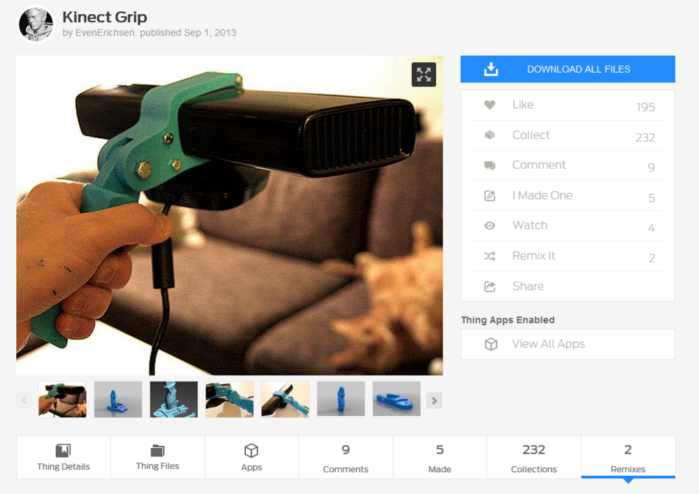
The part that hold the kinect is a good starting point but we have to design our own adpator to fix it on the robot flange.
- I used Cura to slice the provided parts, save the .gcode generated file and upload it to our 3D print server (Repetier Server)
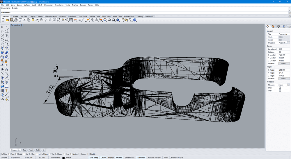
- As you can see bellow, I imported the provided STL into Rhino to get some dimensions to start designing the interface part.
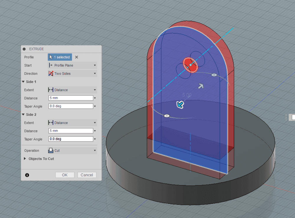
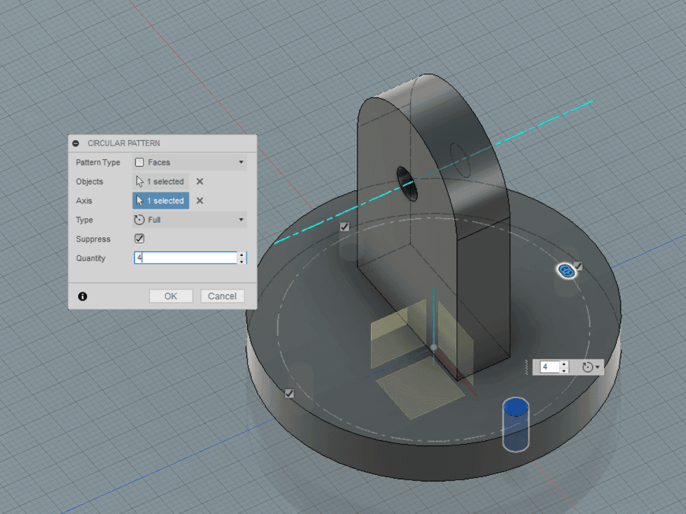
- I also took the calipper to get dimensions of the robot flange and report them into my fusion 360 design.
- Now export the model as STP file, and import it into Cura. Cura is a slicer, a software used to turn a 3D mesh model into G-code (code for CNC machines). For my purpose I don’t need high quality, so I set a 0.3mm layer thickness, and “hight” velocity 60mm/sec moves.

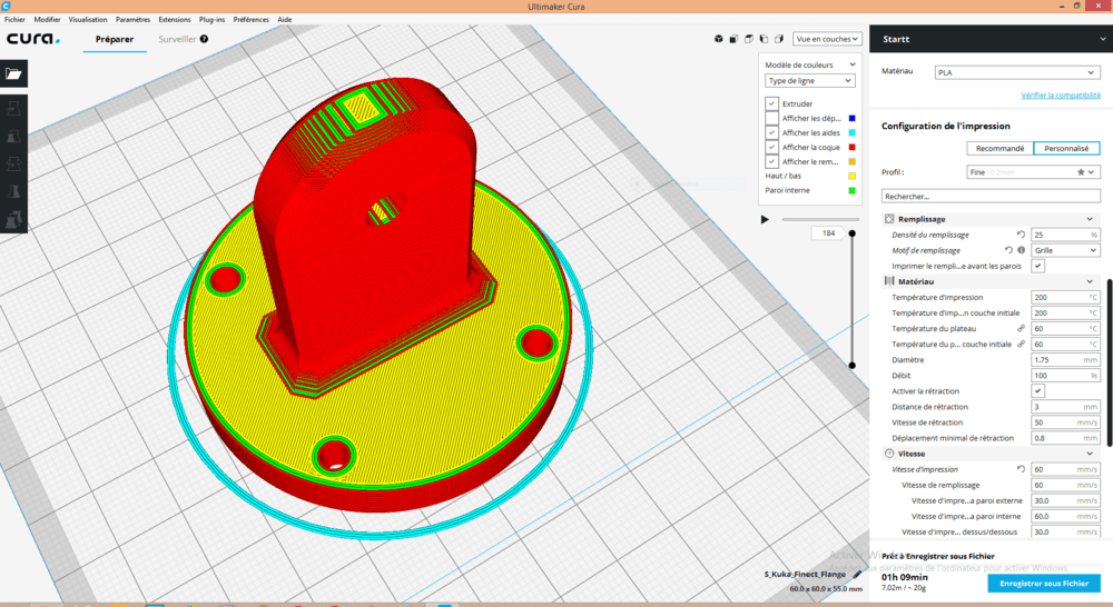
Here are rest of the settings used.
- layer height : 0.3mm
- first layer : 0.3mm
- shell : 1.2mm
- top/bottom : 0.8mm
- infill 25%
- infille pattern : grid
- temperature : 200°C
- bed temperature: 60°C
- filement diameter : 1.75mm
- nozzle diameter : 0.4mm
- Retractation : enabled
- Retractation distance 3mm
- Print speed : 60mm/s
- First layer speed : 30mm/s
- Infill speed : 60mm/s
- Shell speed : 30 mm/s
- Move speed : 120 mm/s
- fan cooling : enabled
- support : disabled
- bed adhesion : skirt
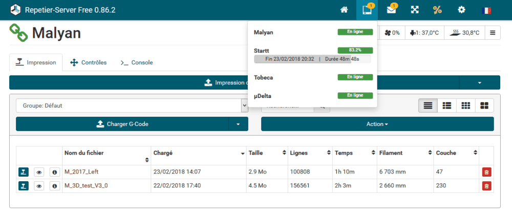
- Import generated gcode file into Repetier server (software connected to our 3D printers that manager print queues)
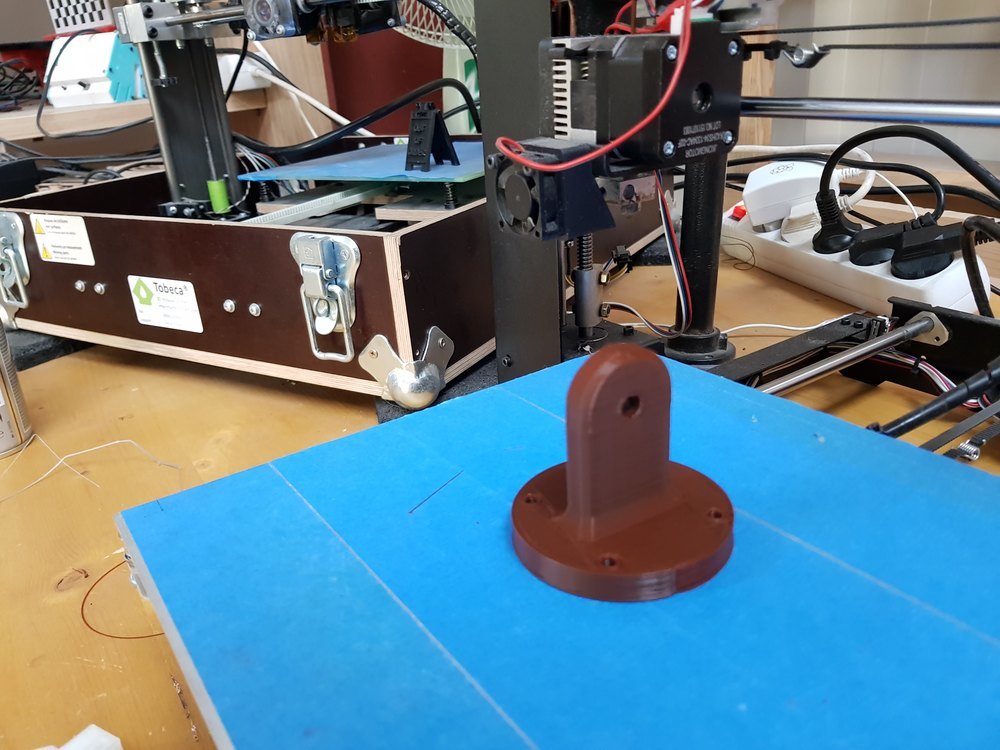
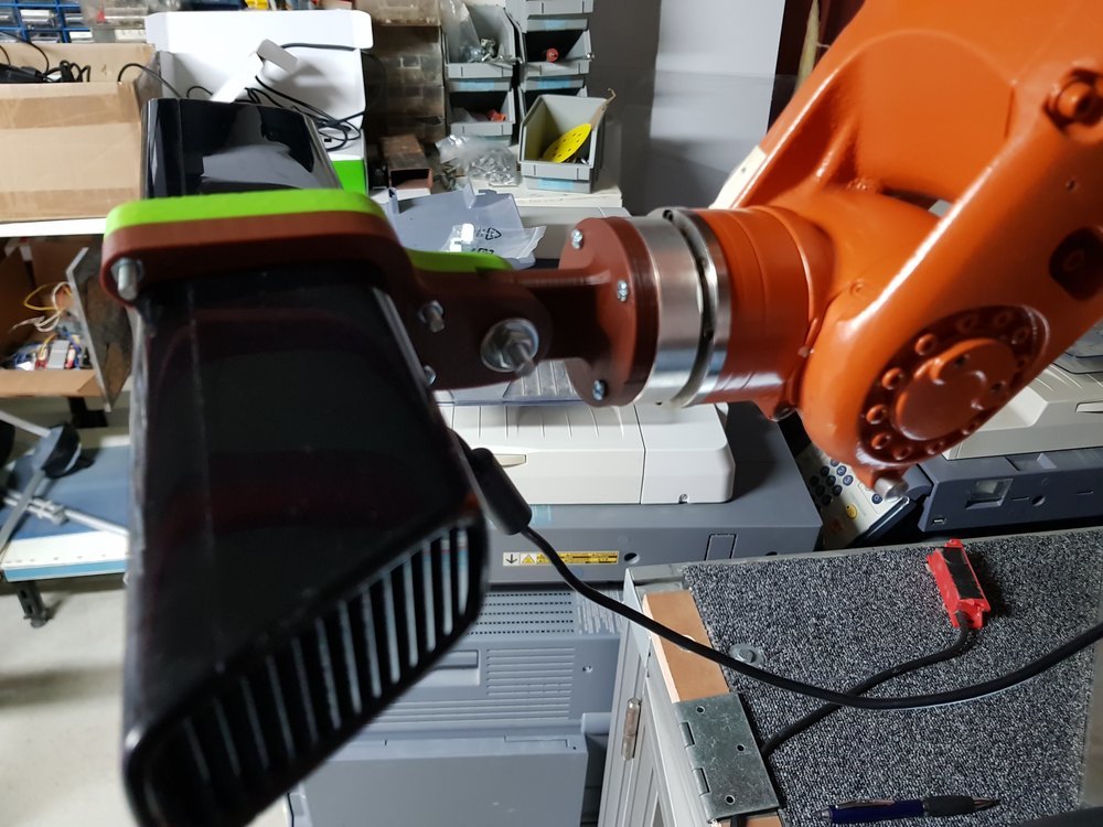
- mount printed parts on the robot flange
Conclusion
This part could have been done using a 4 axis CNC milling machine, but not with a 3 axis beacause of the hole. 3D printing is adapted to this kind of object, because it is fast to make it using a few amount of (cheap) material.
Softwares used:
Files
Kinect to robot Adaptor
Click here to download the adaptor files, including STL and Fusion 360 source
Scanning using Skanect
Prepare kuka
Everything is going well, we can now program the robot to move slowly. The goal is to avoid having surface that are not seen by the sensor, like the top of the head or the neck (as we experienced before). As program I store 3 positions and tell the robot to move circulary from one point to another waiting some seconds.
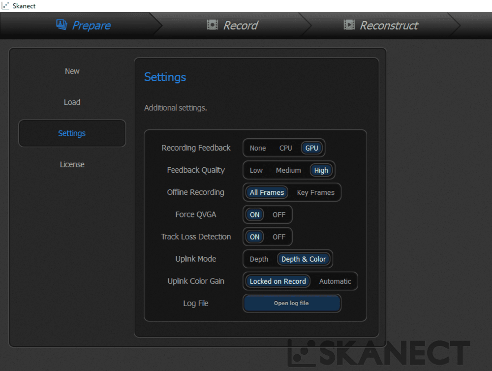
Prepare Skanect:
- Run skanect (we have a pro version) with your kinect plugged
- Check settings, it is better to have a powerfull GPU so you have another option “Depth & high resolution color”
- Create new scan, and click start
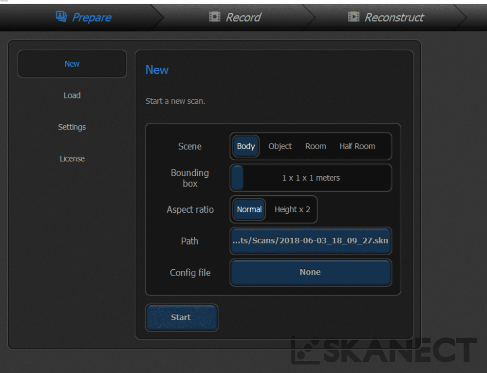
- adjust position of the model to fit in the square, then clik record button start scanning.
- At the same time start Kuka program
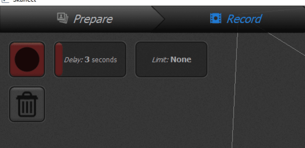
The video below show a short move, but you can easily imagine the scanning process using Skanect Pro that last about 1 minute.
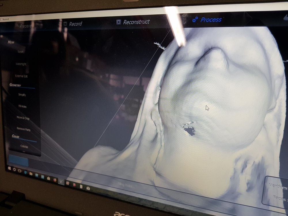
- click finish to stop scan, and wait for some seconds, Skanect is reconstructing the 3D model.
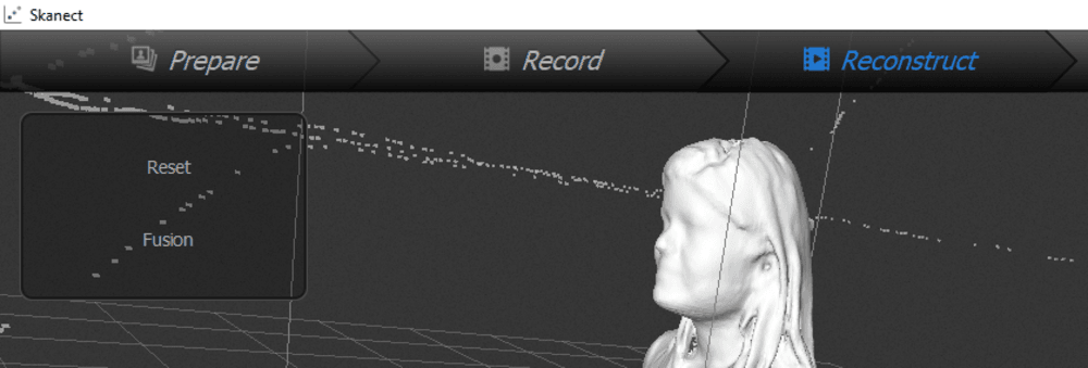
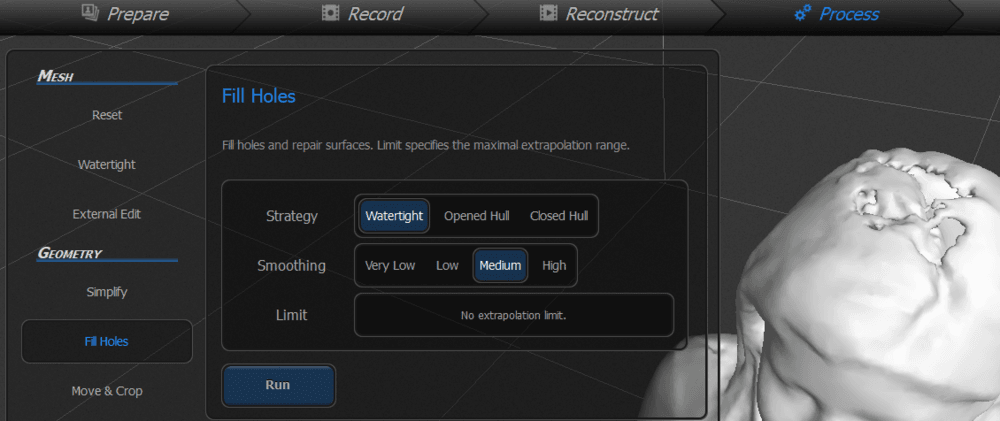
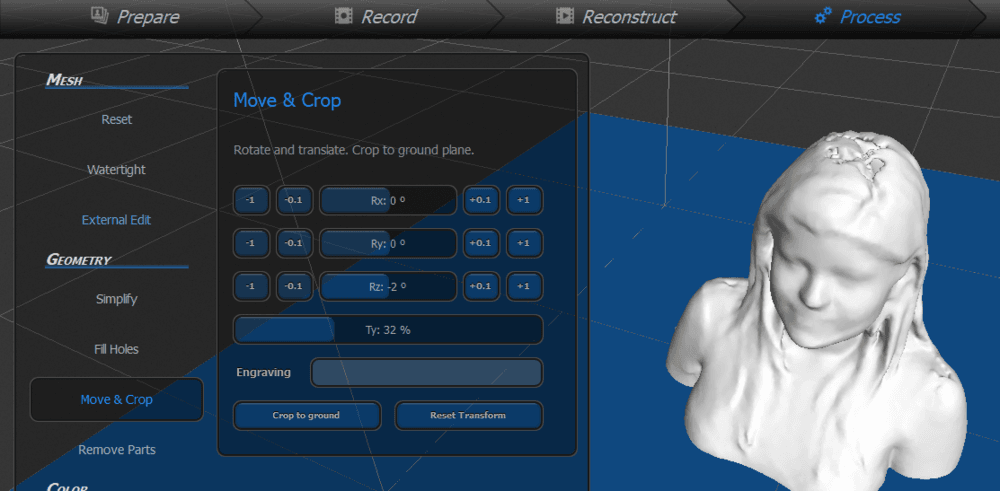
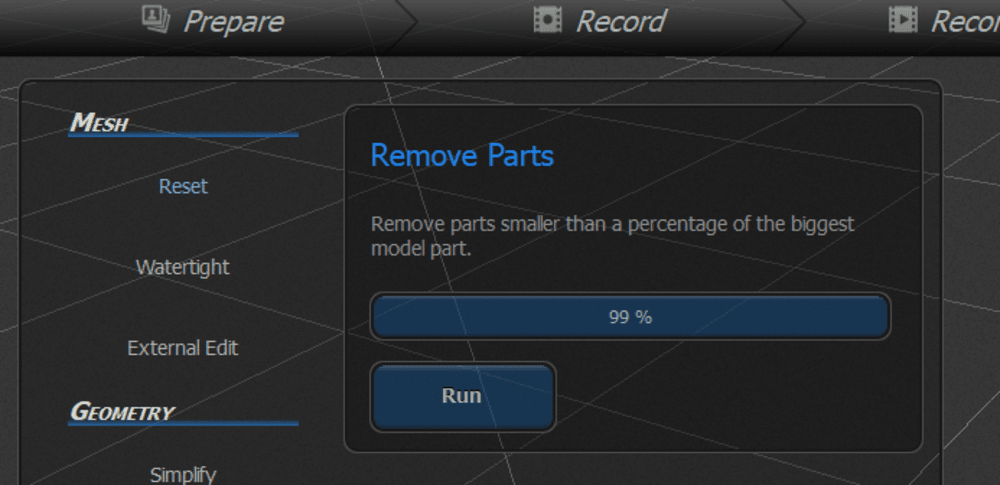
- When done, click on the process tab to clean the scan. Skanect propose some basic operations to repair the captured model, like filling holes, cut parts, clean noises. Then finally save model as STL file. You can reduce the number of polygons.
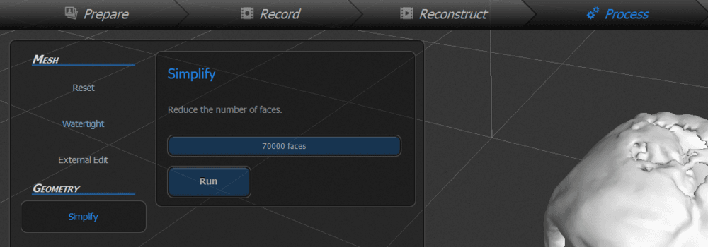
- finally to export the model as STL file, go to Share tab, change settings as following then click export.
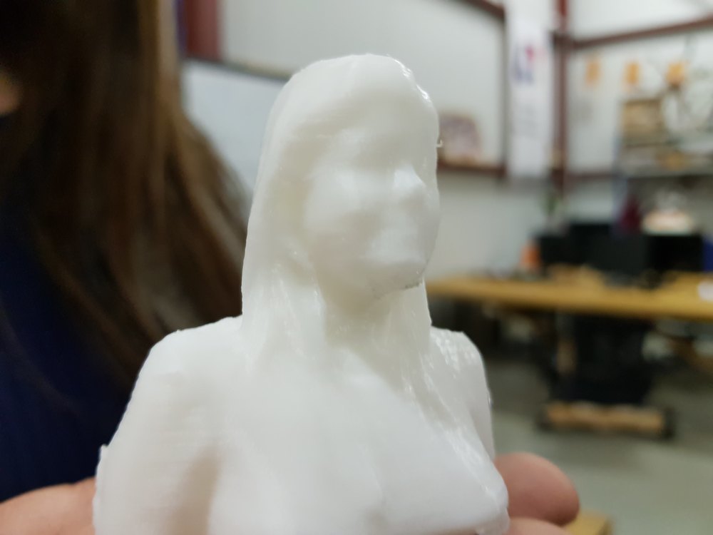
Print it
Slice the model, upload and print it. We used a 0.1mm layer thinkness, but the print last about 4 hours.
Clean the printed piece removing generated supports, and Voilà !
Scanning using Bq cyclop and Hortus Software
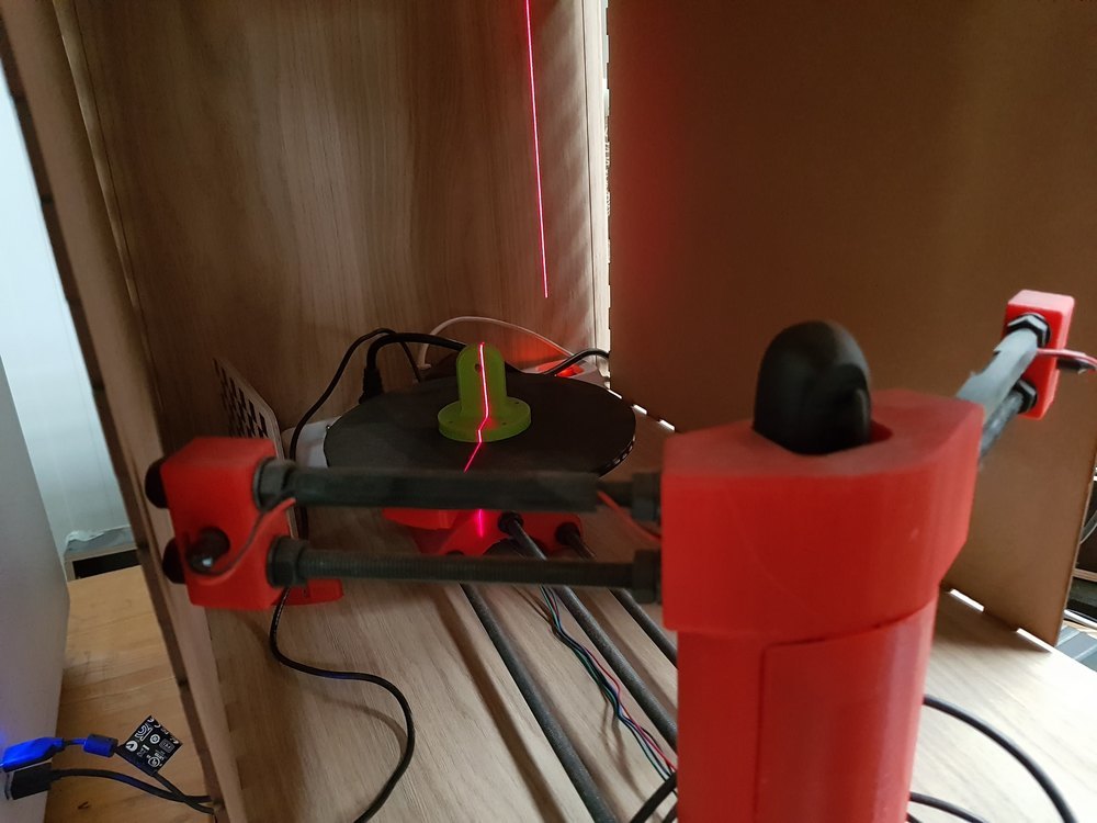
As an extra, I would give a try on a Ciclop scanner we have but we do not use. It’s an open source 3D printed scanner provided by a spanish company called BQ.
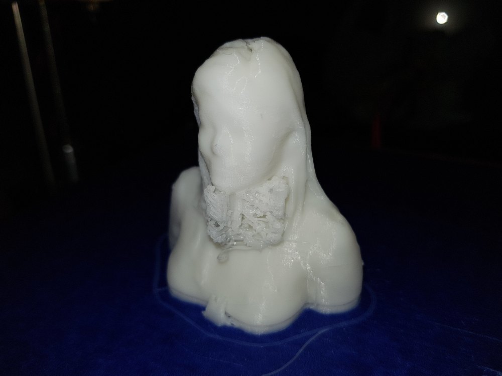
I didn’t spent much time finding the good settings, just have a looks of the part we printed previously to see what we can do. This scanner use 2 lasers and a camera to reconstruct a point cloud.
I run it as it, and the process last a few minutes.
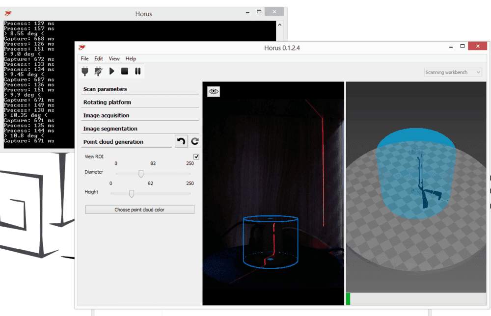
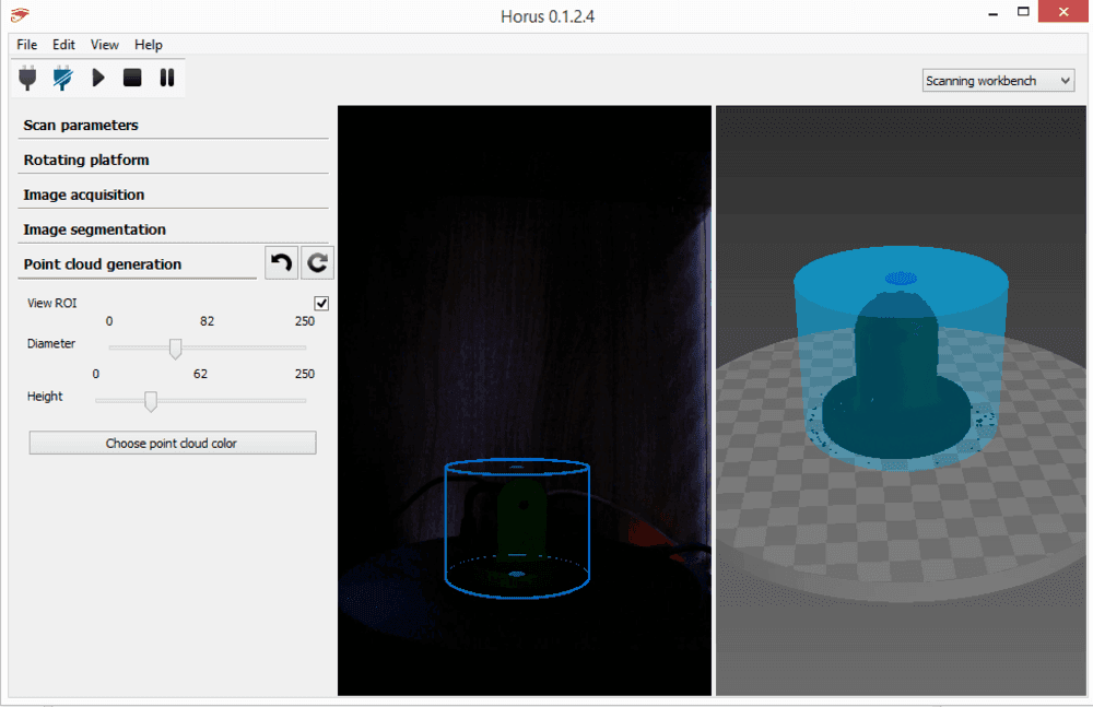
At the end we get a point cloud file (.ply) we have to process using another software.
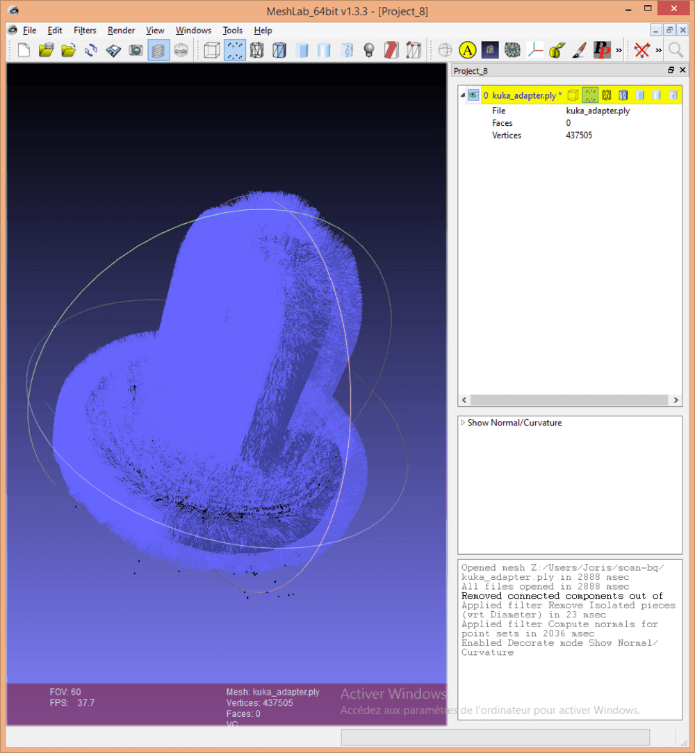
I used Meshlab a powerfull opensource plateform used to modify meshes. But the point cloud we have does not contains faces, we have to create them.
import your ply file into meshcloud. There is a lot of tools, filters, process in there. To create a mesh object from point :
- Create normals: Click on Filters -> Normals, Curvatures and Orientation -> Compute Normals for Point Sets
- Show normals : Click on Renders -> Show normals
- Create meshes using Poisson construction algorithme : Click Filters -> Remeshing, Simplification and Reconstruction -> Surface Reconstruction: Poisson
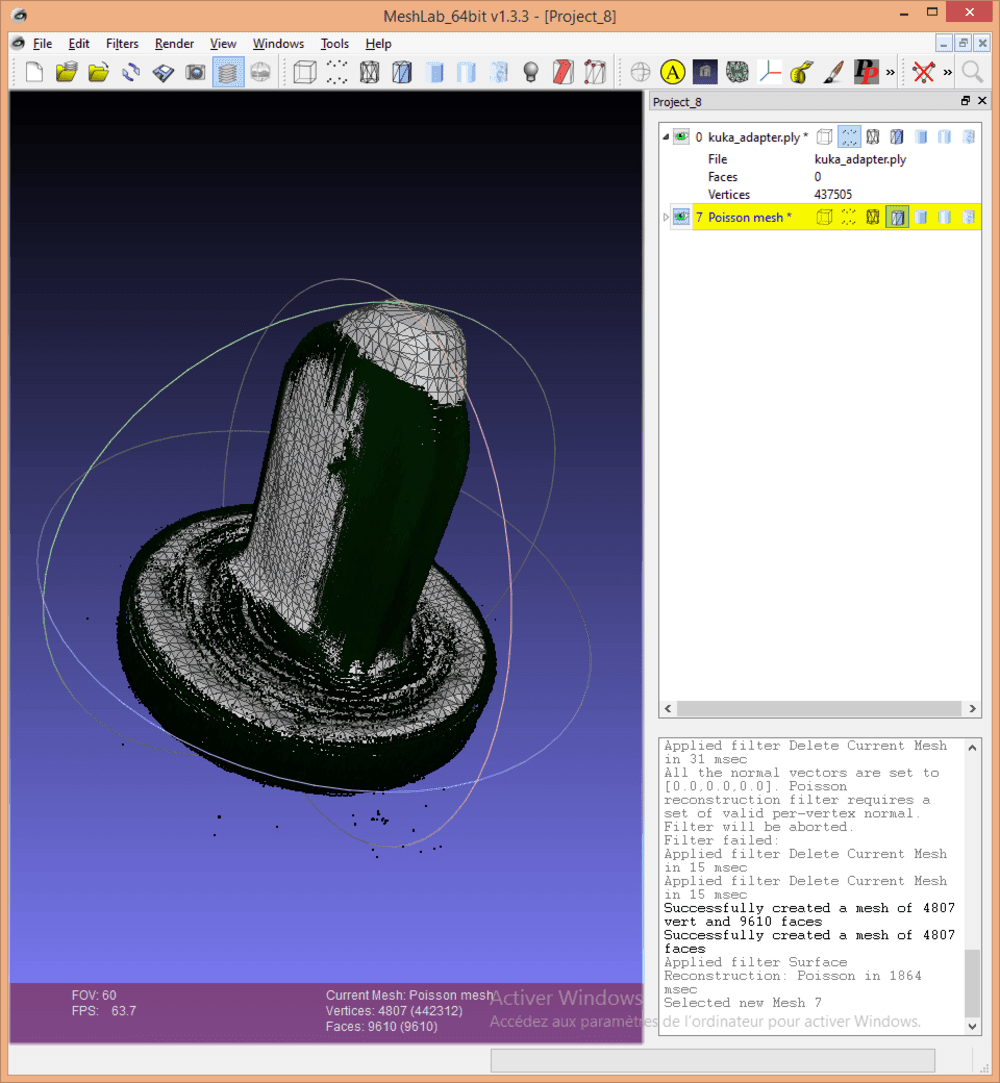
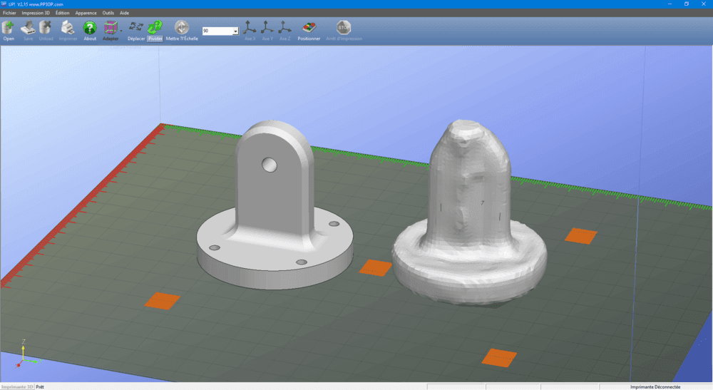
As you can see the result is not terrible. I should spend more time looking for better settings, on scan and on reconstruction.
The is a “Guide for optimum scanning” and links from BQ support web site, but both are broken.
Files
BQ Scan
Click here to download the scan, including STL and PLY
Softwares used:
Scan conclusions
The setup requires a computer with a good graphic card to capture the 3D and images at a reasonable framerate. otherwise you will capture at less thatn 10 frames per second (fps), and you will have to move the kinect device around the object very slowly to prevent scan interruptions.
As I known we can use 4 main technics for 3D Scanning:
- Laser triangulation
- Structured light
- Photogrammetry
- Contact based
The technics used here (laser triangulation) are not good for scanning objects that need accuracy. For exemple you cannot scan a basic cube and have its exacts dimensions. But it is nice for human head size real life objects.
Stay in touch
Hi, I'm
Joris Navarro, from Perpignan (France), a proud dad, a fab director/manager, a teacher, a ceo, a FabAcademy student, but not only. Click here to know more about me.
Check my work for FabAcademy on FabCloud GitLab
@joris.navarro.
Want to say Hi ? Please send me a message.