
Electronic design
Week 7 - Electronic design
Here you will find my work description during this seventh week
General info
Class notes
Individual Assignement
-
Redraw the echo hello-world board, add (at least) a button and LED (with current-limiting resistor), check the design rules, make it (if you have time this week, test it).
-
optional: simulate its operation. Measure its operation
Usefull links
Design Hello board in Eagle
EDIT FROM WEEK 9: this design is not correct, see Week 9 assignement for explainations – Jump to Week 9
During the Eagle master class, Santi show us how to start with Eagle.
Install Eagle (Windows)
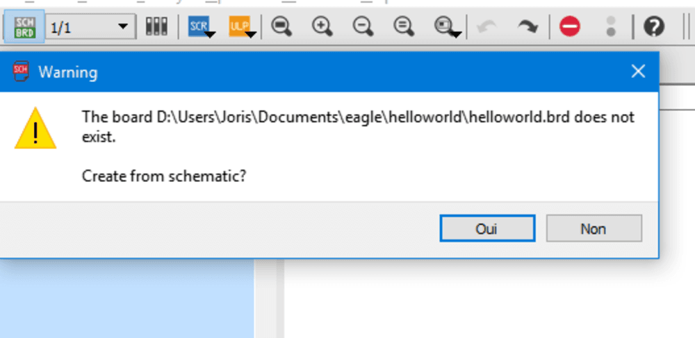
First create Eagle project: You wille create 2 files : schematics and board
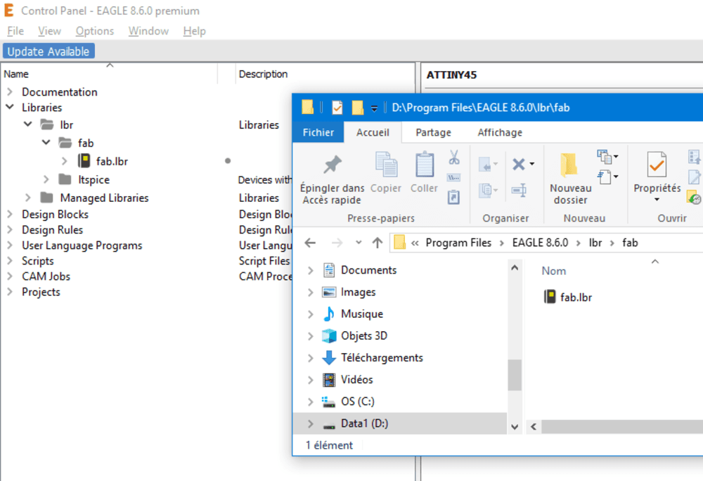
Then we have to import fab.lbr the fablab inventory component set that we will use.
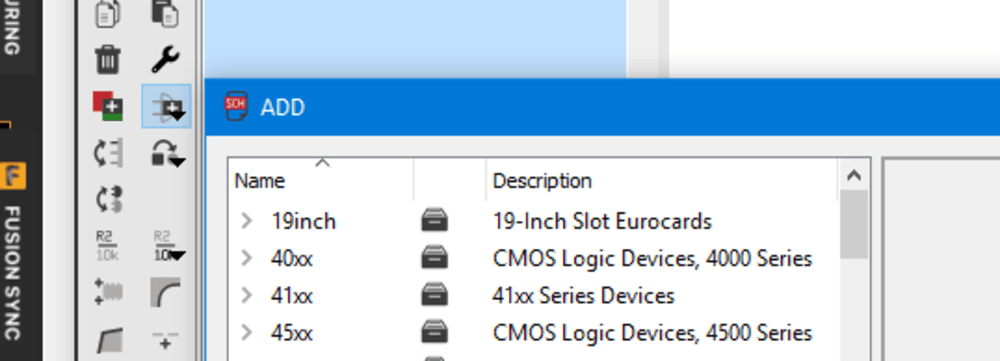
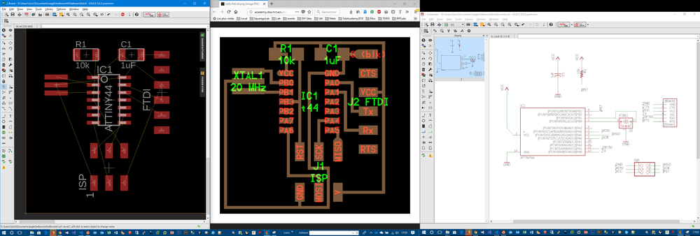
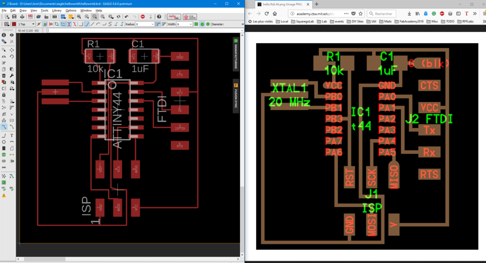
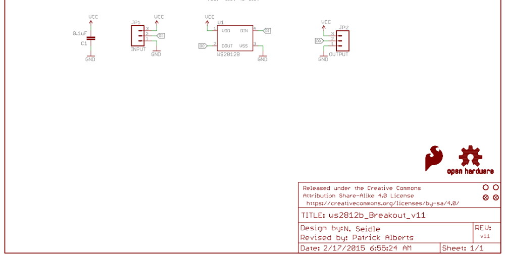
Step by step we redesign the Hello board in schematics. Add components following the given picture. Add values, then add routes. Those routes are symbolics here, we have to set them manually in the board window.
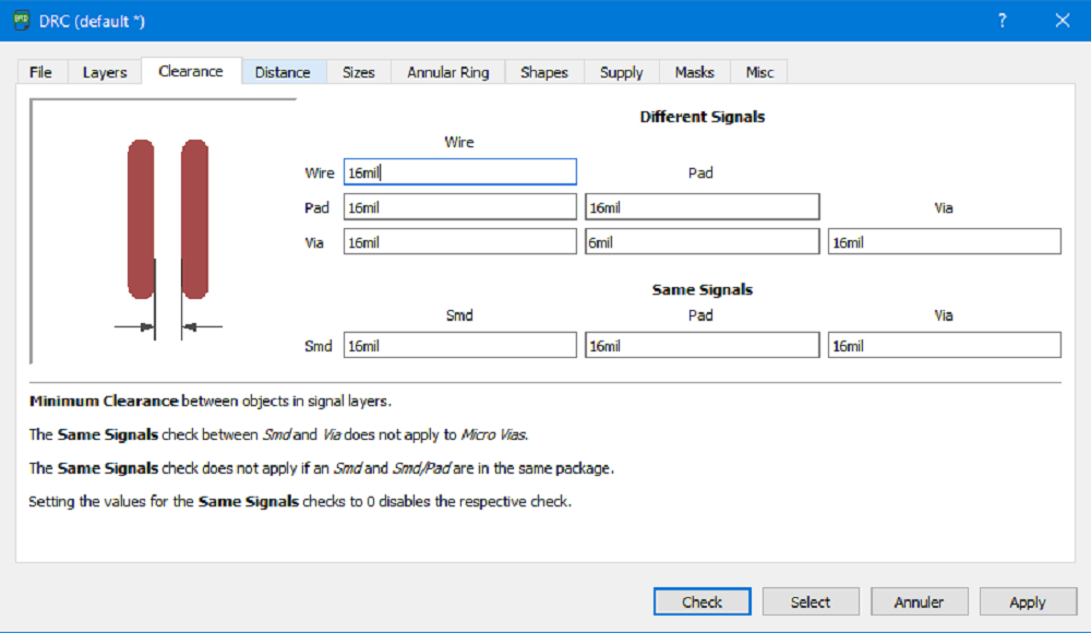
As you can see the trace are not in the good thickness. I might have changed the DRC Design Rules Checks before wirging component. (Click on DRC button at bottom and set clearance according to your milling machine capabilities). See image bellow to check the DRC values I used (16mil everywhere, that is 0,4064 mm, and the end mill is 1/64inch = 0,396875 mm)
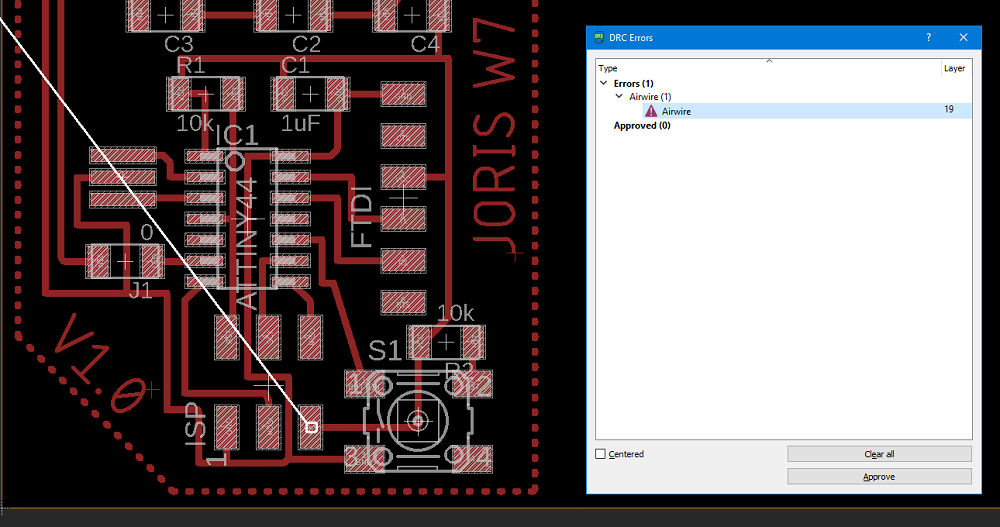
Running the DRC will warn if there are issue on the design.
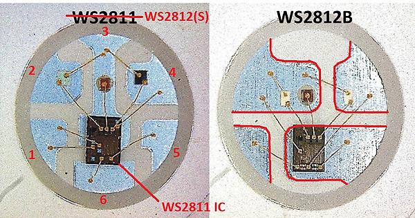
Add some extra components. For my final project I want to use some WS2812B known as Neopixels. There are individually addressable RGB LED. They have an intergrated WS2811 controller that (I am not sure about that) uses a I²C bus to chain several LED using one Data pin.
Add the button
Add WS2812b, component available on adafruit library. I red the datasheet and I need to add an 0.1uF capacitor for each LED according with documentation.
AN ERROR WAS MADE HERE !! I misunderstood the schematics and I wired the capacitor not correctly.
Then I realise I may have to use a ATTiny84 instead of 44 because it has more memory. That memory is mandatory to use neopixel library. I change the IC to ATTiny 84 that has the same fingerprint.
After reading some documentation I start adding then in the schematics with a button.
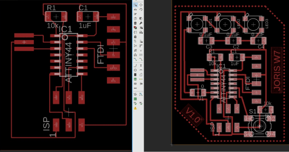
To the finish board i add a simple text. After add the text, go to their properties and change the SIZE parameter to 0.15 or above, and at the FONT parameter i choose “vector”.
Here is the final result (at least for version 1.0)
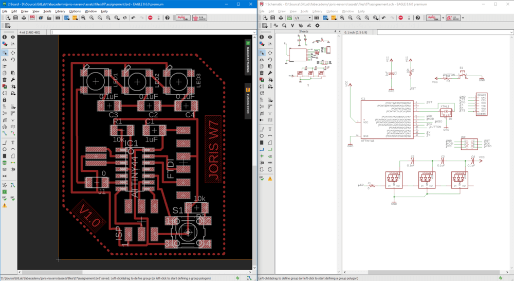
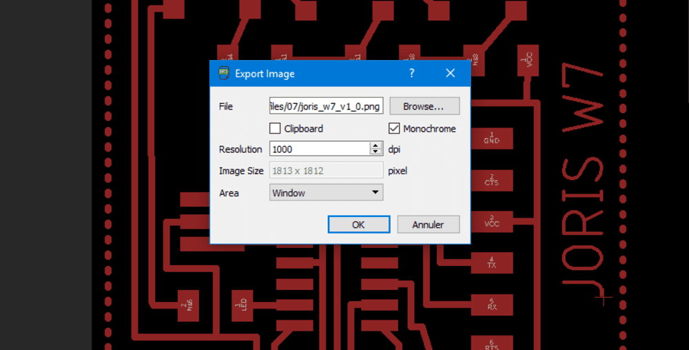
After all is finish, lets export the .png file to mill it.
Milling the board
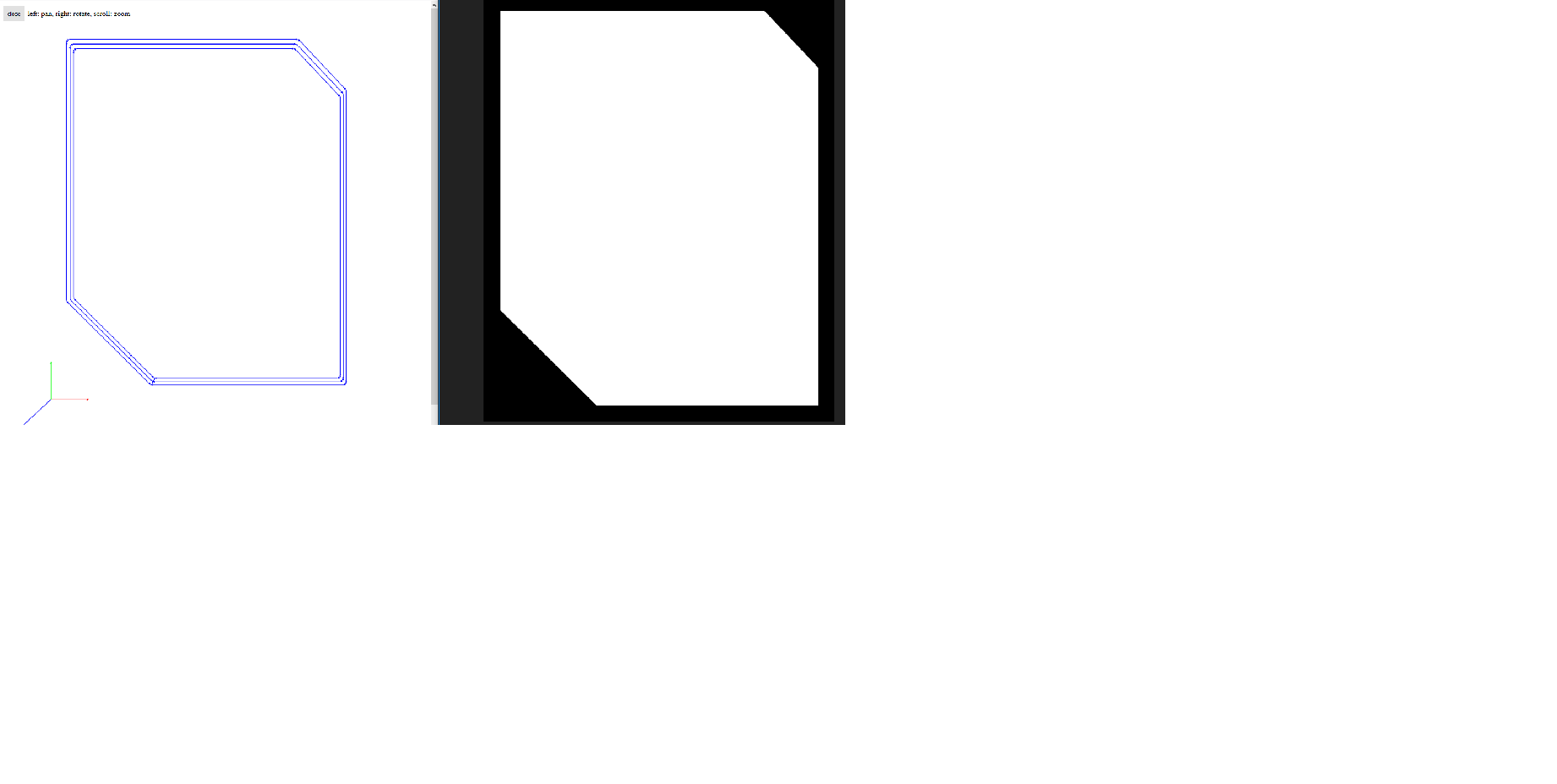
First we have to generate the outline raster file, I did it with photoshop.
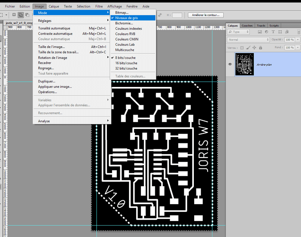 . File is available below.
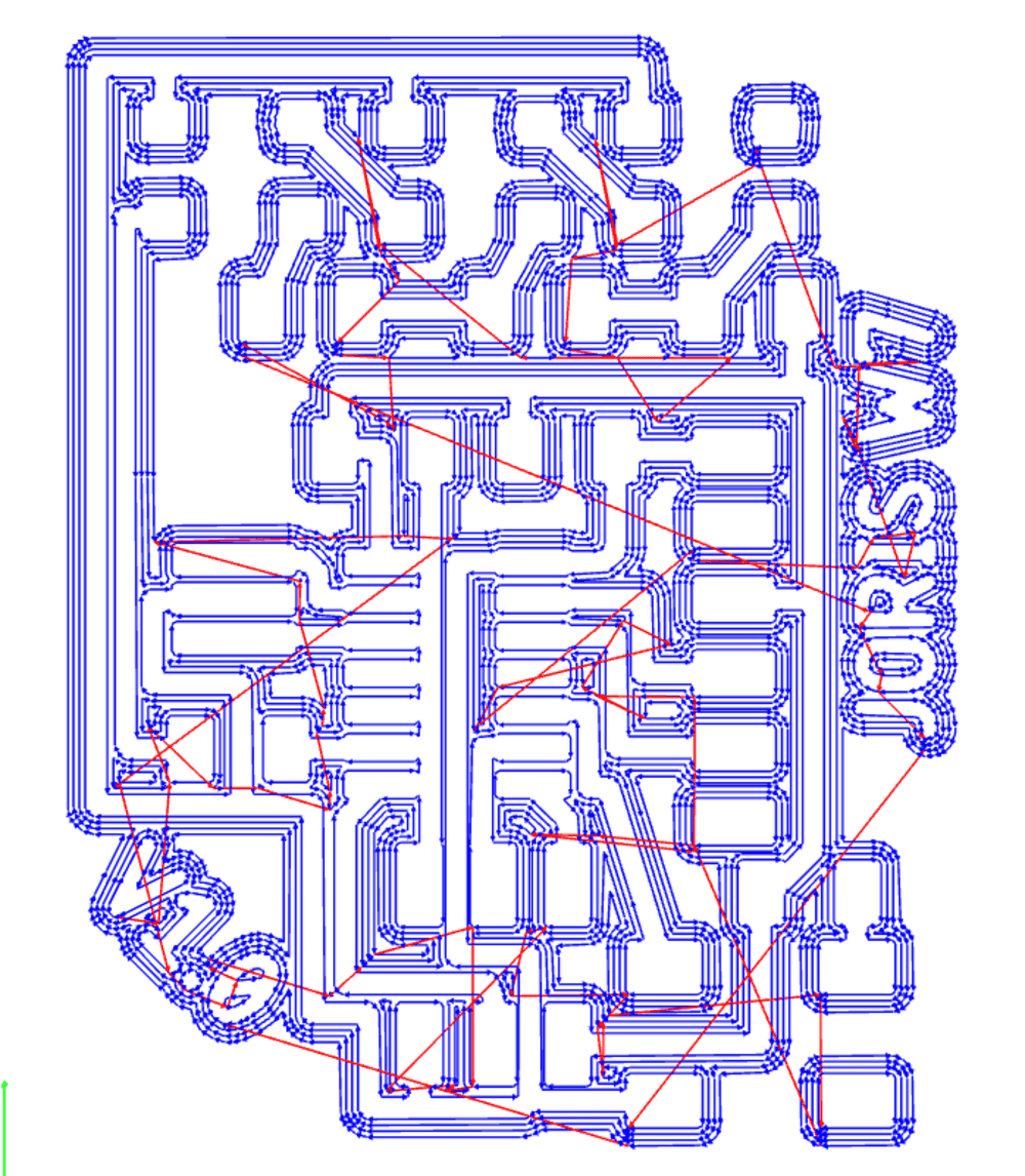
I used Mods to generate RML file.
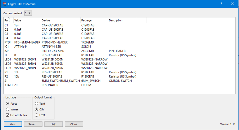
From Eagle I exported the BOM (Bill of Material), to let me pick components during milling process.
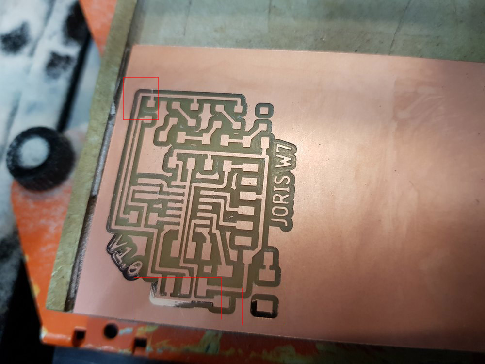
The first milling job has not cut all the copper so I did it again after setting the Z origin 0.10 mm lower. But some corners are not well cut despite I checked the flatness of the board. I decide I will remove the last part with a knife.
Then mill the outlines
Outline job did not went well neither. Because other students wanted to use the machine I set the speed at 100% but before the end of the process, the board unsticked.
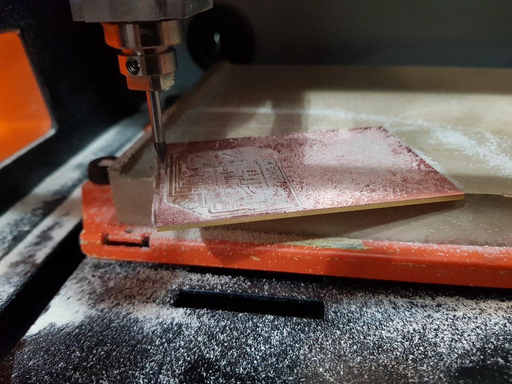
Neverming the board was cut enought and I was able to break it properly.
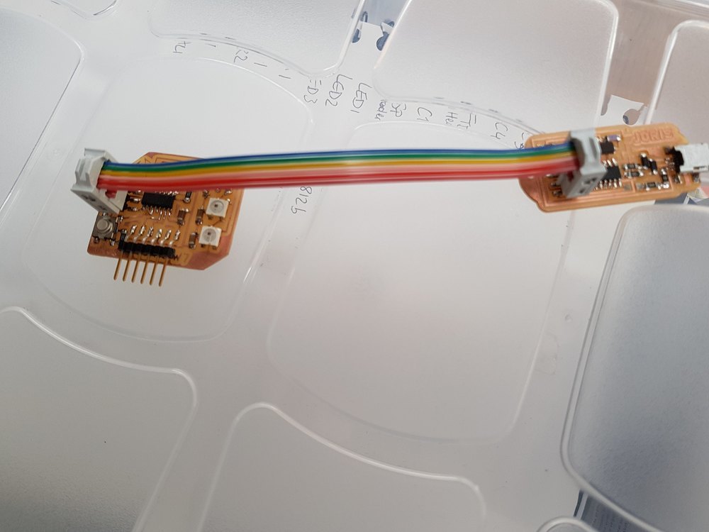
Soldering
I solder all the components and start testing traces. Here is the result.
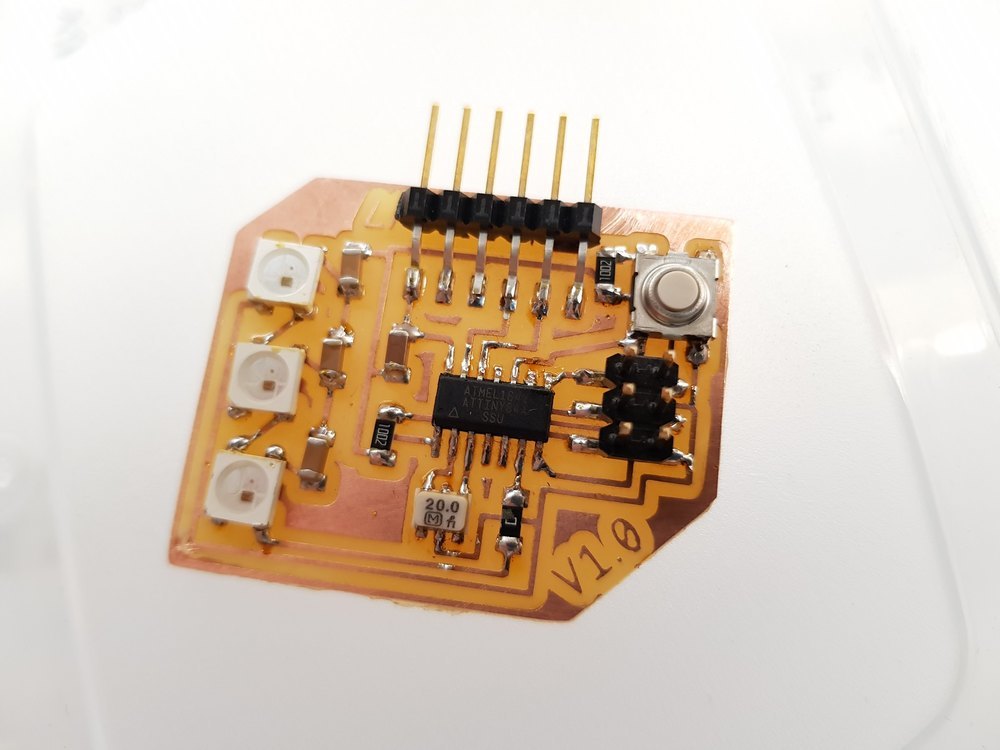
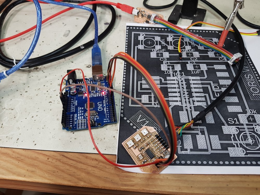
Everything looks OK, let’s test it with my FabISP.
Programming
The FabISP I did two weeks ago will be sused to burn the bootloader of the ATTiny84.
But first we have to setup Arduino IDE to do it.
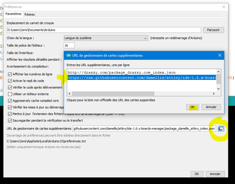
By default there is no ATTiny board proposed by Arduino IDE. So We have to add them using the Board Manager.
Open File -> Preferences and add an official board source list.
https://raw.githubusercontent.com/damellis/attiny/ide-1.6.x-boards-manager/package_damellis_attiny_index.json
Go to Tools -> Board manager, look for ATtiny and install package.

Now we can select ATTiny familly in the board list.
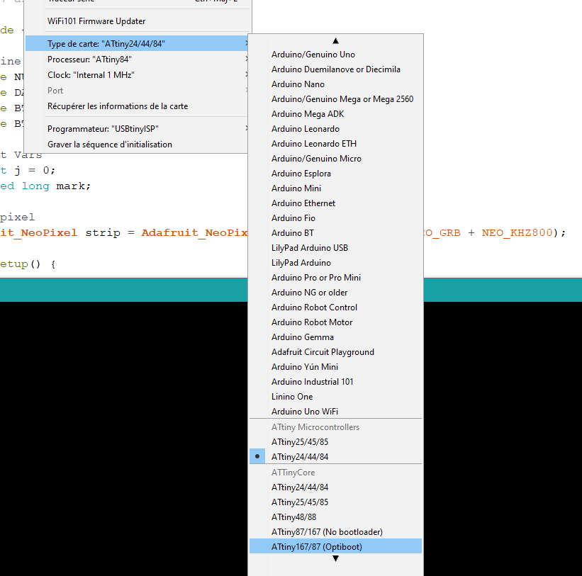
Set controller to ATTiny84.
Set the Clock as 20 Mhz External because we are using a resonator.
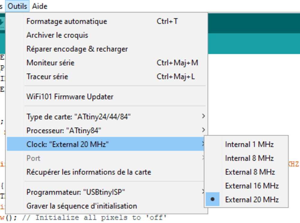
Set the programmer as USBtinyISP.
To set the fuses, Click on Tools -> Burn Bootloader
And BOOM Unable to communicate with the controller.
Troubleshooting
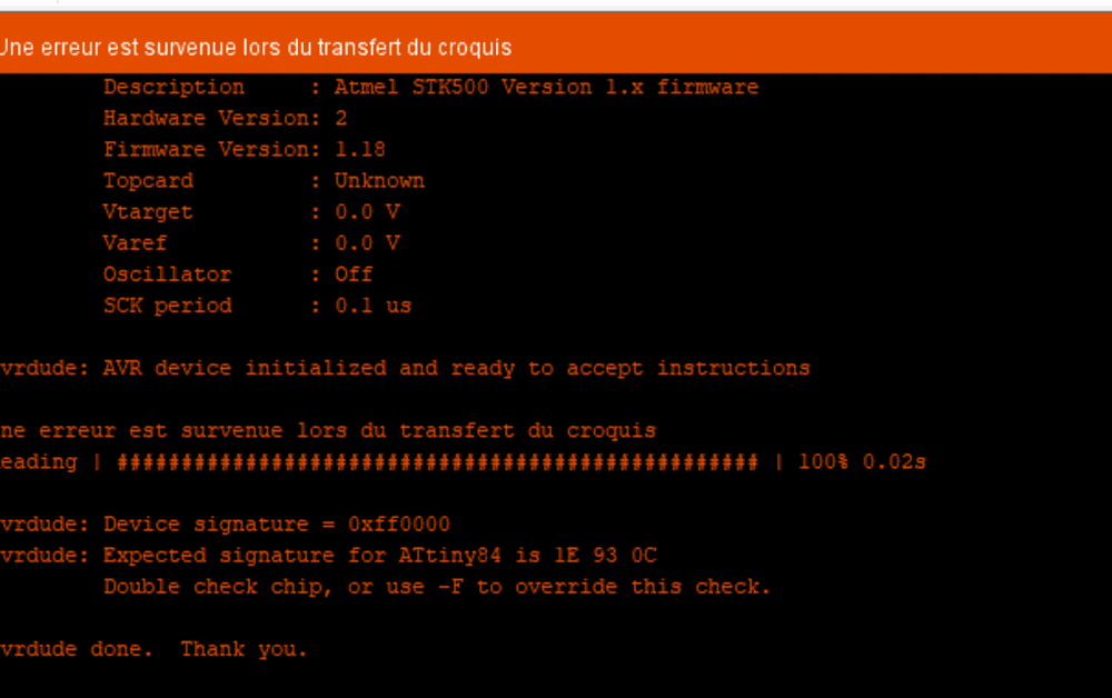
Signature is 0. I read a lot of forums, try a lots of different configurations. I used an arduino Uno Board as ISP, Flash the arduino Uno using the FabISP. Nothing ! The FABIsp works well, arduinoISP too.
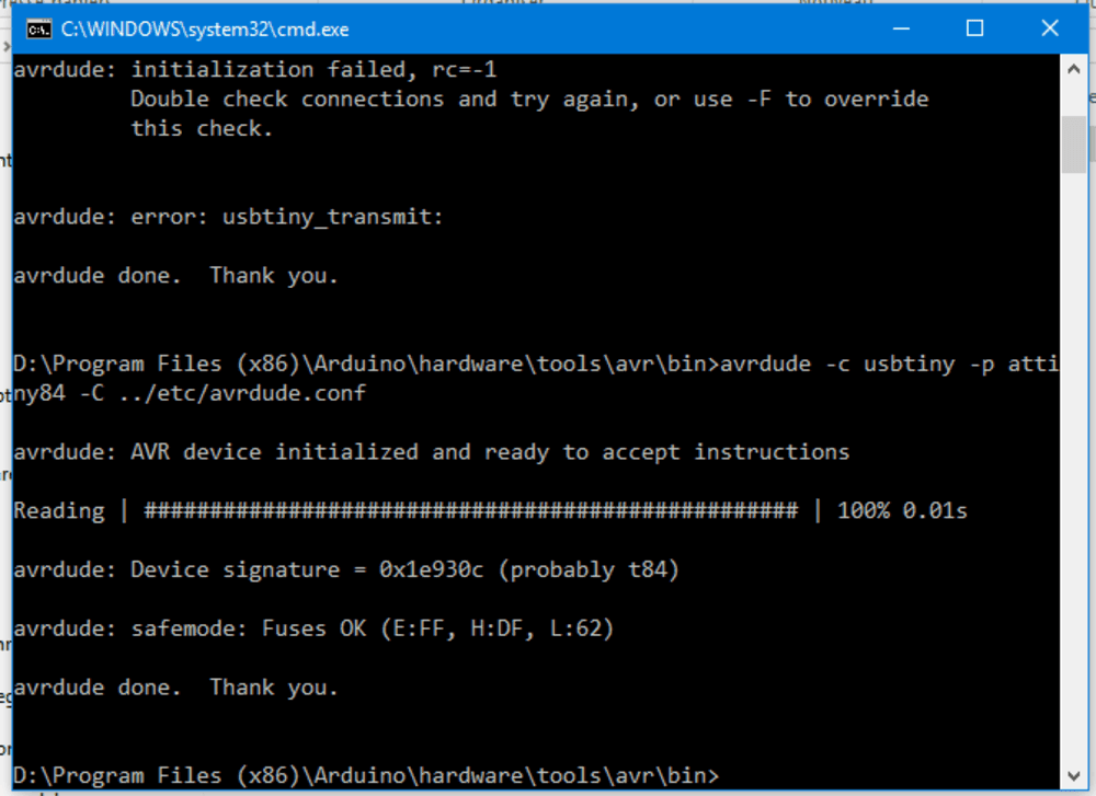
Using avrdude software in command line is so usefull to try communicate with the controller but I start thinking that the controller is dead.
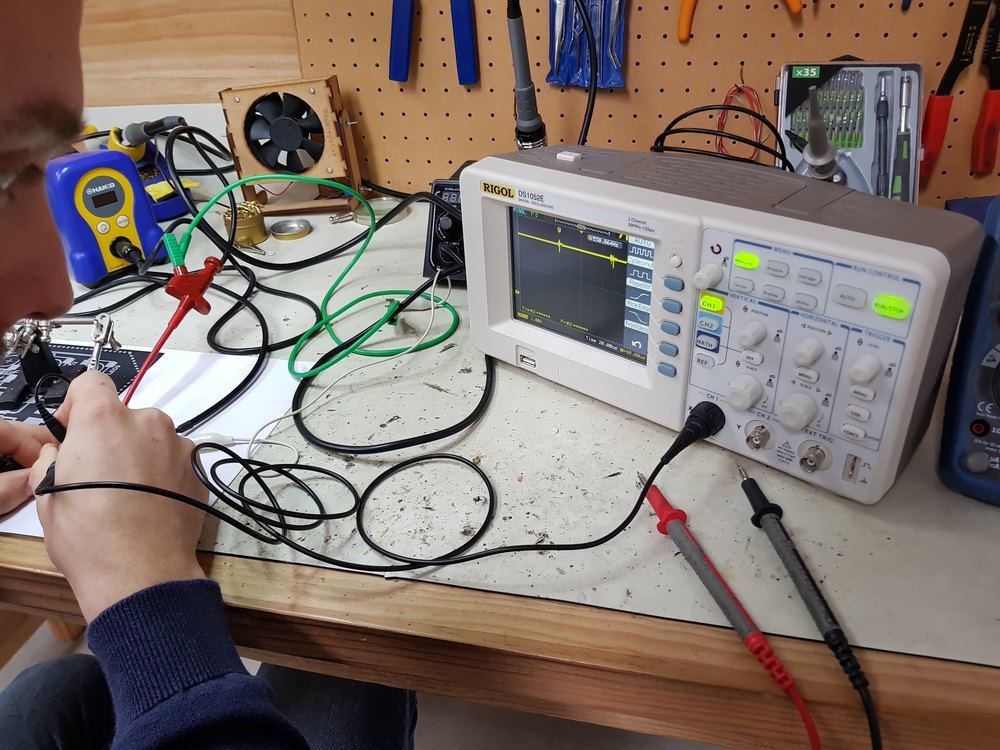
I tested traces again and again until I found out that the pin #6 used as data has 5V ?!?
It’s time to Franken hack the board.
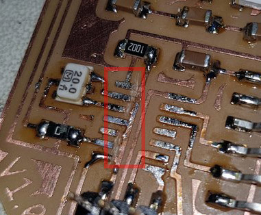
I decided to unsolder the controller to change it by a ATTiny 44 (the only one I have). And I discovered something anormal.
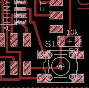
As you can see in the image bellow one trace is not cut properly due to a distance bug.
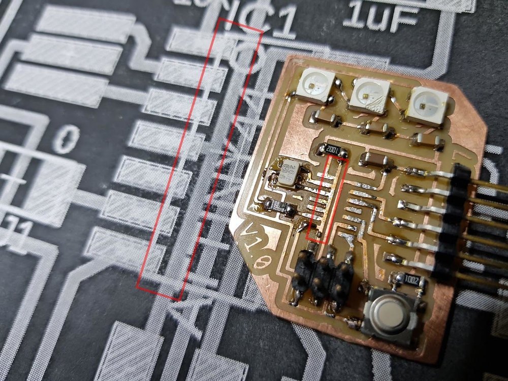
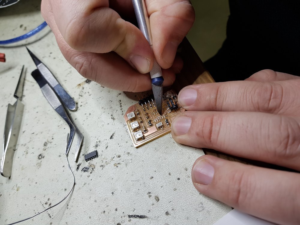
I used a scalpel to scratch the bad traces.
I solder the same controller to check if it is dead.
And fortunately it is not !
Using Avrdude to check tell me that we can communicate with the controller.
I checked using Arduino IDE we can now burn the bootloader. Using a sample code that uses the Neopixels relveals some design issue. The led are not wired correctly, I thing I should have added a higher resistor before the LED data bin. I saw a green light but cannot reproduce, maybe the LED are dead.
I need to find new ones.
Antoher point was the frequency of the clock. Neopixel are made to be used at 8MHz or 16MHz the code cannot compile unless I set 8Mhz (internal) as fuse (bootloader)
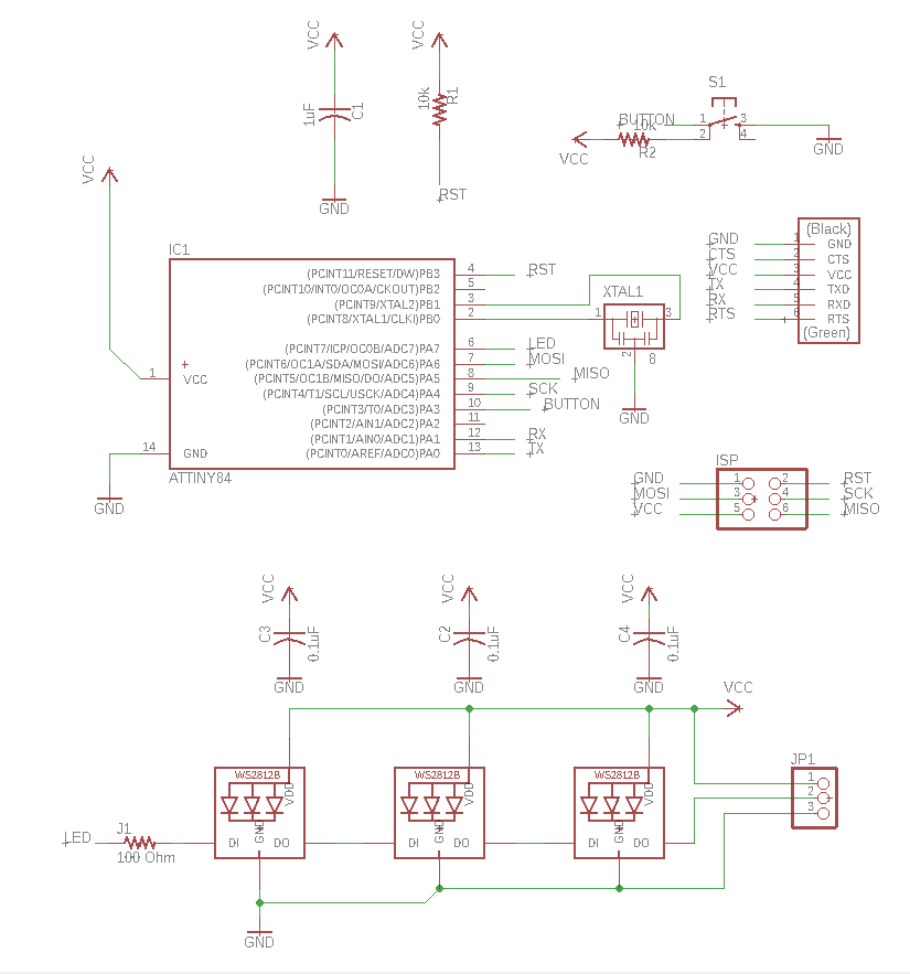
I need to update the eagle file with the change I made but I don’t have a fully fonctionnal version yet.
The board is not finished but here are the fixed schematics
Files
FIXED version not included, if you want to use it you have to modify the capacitor wiring accoring to Week 9 modifications – Go to Week 9 - You can also download the new version of the eagle files (but not finished)
Click here to download the eagle files
Click here to download the milling files, including traces and outlines PNG, and RML files
Stay in touch
Hi, I'm
Joris Navarro, from Perpignan (France), a proud dad, a fab director/manager, a teacher, a ceo, a FabAcademy student, but not only. Click here to know more about me.
Check my work for FabAcademy on FabCloud GitLab
@joris.navarro.
Want to say Hi ? Please send me a message.