
Networking & Communication
Week 14 - Interface & Application Programming
Here you will find my work description during this fourteenth week
General info
Class notes
Assignments
- individual assignment: design and build a wired &/or wireless network connecting at least two processors
- group assignment: send a message between two projects
This week
This week we are going to discover networks, protocols and communication. There are several kind and level of communication, we cannot see all but I wanted to study some of them esoacially the bluetooth radio communication that I will use for the final project. Another aspect I wanted to study is a low level (electronic) communication (serial, I²C). Unifortunately I would not be able to test everything then I focused my work this week on the BLE communication.
First here are some usefull link and study thought.
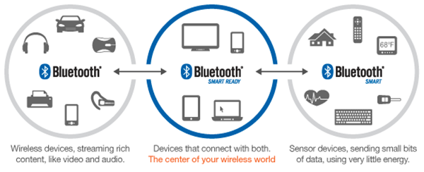
Bluetooth Low Energy
BLE means Bluetooth Low Energy also called Bluetooth Smart. Has been released in 2010 with the version 4.0 of the Bluetooth Specifications.
With this new protocol version we can discover a new kind of devices.
- Classical BT devices
- BLE devices or BT smart - called single-mode (cannot connect with classical BT)
- BT smart ready - dual mode (can connect with Classical BT and BLE)
Some technical data:
| Technical Specification | Classic Bluetooth | Bluetooth Low Energy |
| Distance/Range | 100 m (330 ft) | 50 m (160 ft) |
| Over the air data rate | 1–3 Mbit/s | 1 Mbit/s |
| Application throughput | 0.7–2.1 Mbit/s | 0.27 Mbit/s |
| Active slaves | 7 | Not defined; implementation dependent |
| Security | 56/128-bit and application layer user defined | 128-bit AES with Counter Mode CBC-MAC and application layer user defined |
| Robustness | Adaptive fast frequency hopping, FEC, fast ACK | Adaptive frequency hopping, Lazy Acknowledgement, 24-bit CRC, 32-bit Message Integrity Check |
| Latency (from a non-connected state) | Typically 100 ms | 6 ms |
| Total time to send data (det.battery life) | 100 ms | 3 ms, <3 ms |
| Voice capable | Yes | No |
| Network topology | Scatter-net | Star-bus |
| Power consumption | 1 as the reference | 0.01 to 0.5 (use case dependent) |
| Peak current consumption | <30 mA | <15 mA |
BLE has 2 access mode : Frequency Division Multiple Access (FDMA) et Time Division Multiple Access (TDMA - for connections and events).
The BLE has 2 levels that communicate through a Hardware Controller Interface (HCI):
- Controller : low level logic (transport)
- Host : high level logic (données)
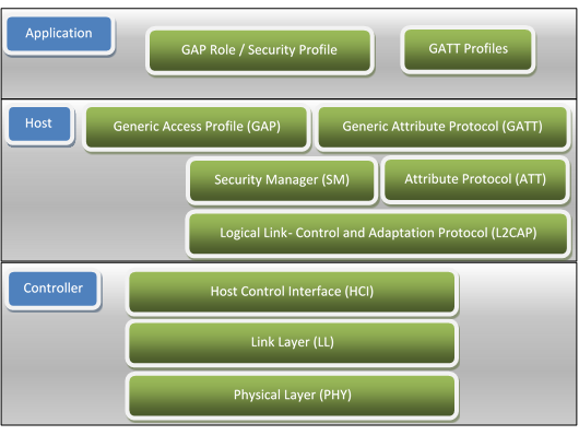
GAP and GATT are fundamentals.
- GAP (Generic Access Portal) is the layer that manage connection between 2 devices
- GATT (Generic Attribute Protocol) manage the data (server/Client)
- LL (Link Layer) define the master/slave mode
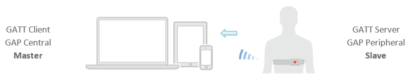
There are 2 ways to send data : connected mode (private, secured -or not- communication), or advertising mode (public broadcasted communication)
GAP profiles:
- brodcaster (advertising) : for device that only send public data (advertising events)
- vs scanner/observer (advertising) : for device taht only recieved data (advertising events)
- peripherical (connected) : for device that can be connected to one or more devices - need a slave controller
- vs central (connected) : for device that init connections - need master controller
GATT protocol:
- Smart Ready device (smartphone) is the master and will establish a connection with the LE (smart/single-mode) device - slave
- The slave is the GATT server ans the master the client
- The server propose data called Attributes
- Those attributes can be characteristics or services (collection of characteristics)
- Characteristic contain description, value (the data), value descritpion
Usefull resources:
-
Generic Attribute Profile (GATT) services and caracteristics
-
To view Neil’s explaination during class go to 55’13
Serial Commands
to enter command mode, send $$$
SET/GET (S, G) Set and Get commands are used to configure features and functions of the RN4871 module. Set commands needs 1 parameter To take effect set commands have to be followed by a reboot (using R,1)
Command Type(S)+Command ID(N)+Delimiter(,)+Parameter(DeviceName)+End of command(
Set commands
- S-,MyDevice : set serialized bluetooth name
- S$,# : change the char used to go to command mode (default is $, and you need $$$ for command mode)
- SA,2 : change authentification mode (pin or not)
- SB,09: set baudrate to 9600 bauds (parameter is hexa/8 00-0B)
- SC,2 : Connectable and NonConnectable advertissment setting (0,1,2)
- SDA,0340 : BT SIG set GAP appearence (heartbeat, watch, … list)
- SDF (firware revision), SDH (hardware revision), SDM(model name), SDN (manufacturer name), SDR (software revision), SDS (serial number), SF (factory reset)
- SGA (adjust power output)
- SM,1,000E : start application timer 1, expire in 9 sec
- SN,DeviceName : set device name
- SO,1 : enable low power mode
- SP,1234(56) : set pin 4-6 digit
- SR,0x4000 : set supported feature (no prompt, reboot after disconnection, …)
- SS,C0 : set default service (Support device info and UART Transparent service)
- ST,0x0006,0x0006,0x0000,0x000A : connection setting (Minimum interval, Laximul interval, latency, timeout) iOS has specific requiement for this
- SW,0C,01 : configure pin function (assign P16 to low baterry indication)
Get commands
- GK : Get current connection status (none or
,<Address Type>, ) - GNR : get peer device name
- GA (… GW) get the value stored by set command (get authentification, get pin, …)
action commands
-
- : toggle echo (on/off)
- $$$ : enter command mode (and display prompt CMD>)
- — : exit command mode (display END)
- !,1 : if UART Transparent service is enabled (SS) enter remote command mode
- @,2 : read analog pin 2 (@,4 read current VDD)
- |I,06 : Read multiple digital pins ( Read digital I/O P2_4 and P3_5. If return value is 04, then P2_4 is low and P3_5 is high)
-
O,07,05 : Write multiple digital pins (Set digital I/O output on P2_2, P2_4 and P3_5, Set P2_2 and P3_5 high and P2_4 low) - [,1,3,00A0,0050 : PWM (not on RN4871)
- &,DF1234567890 : generates and assigns a random address to the local device
- &C : clear random address
- &R : generates and assigns a resolvable address to the local device
- A[0050,005E] : start advertissement with interval of 80ms for 60sec
- B : bound means secure connection (for already connected devices)
- C : try connect the latest bonded device
- C,0,00A053112233 : connect to public (0, or private 1) BLE 00A053112233 address
- C2 : connect to 2nd stored device (up to 8), use LB to display stored devices
- D : display “critical” device info (name, pin, features, authent, …)
- F : start scanning
- F,01E0,0190 : Start inquiry with 300 ms scan interval and 200 ms scan window
- I : start UART transparent mode
- IA, IB, IS and NA, NB, NS set the advertisement and scan response payload form at, respectively (2 parameters IA,01,05 to add a AD structure with Flag AD type)
- IA,Z clear all advertissement content
- JA,0,112233445566 : add mac address to whitelist (1 if private)
- JB : add all currently bonded to whitelist
- JC : clear the wite list
- JD : display whitelist
- K,1 : kill active connection
- M : estimate signal strenght (response RSSI)
- O,0 : sleep immediately, enter low power mode
- R,1 : Reboot
- T,0190,0190,0001,03E8 : Request Connection Parameter to use interval 400 ms, latency 1, and 1000 ms timeout
- U,1 : remove bound number 1
- U,1,Z : remove all bond info
- V : display firware version
- X : stop scan
- Y : stop advertissement
- Z : Cancel connection establishement
For debugging purpose:
- LB : list bonded devices
- LC : lists the available client services and their characteristics
- LS : lists the available server services and their characteristics
- LW : lists stored scripts
I²C & SPI commands
Not explored here
Service configuration commands
- PS,11223344556677889900AABBCCDDEEFF : define private service
- PC,11223344556677889900AABBCCDDEEFF,1A,05 : sets private characteristic (readable, writable, accept 5 octets) - must used PS before
- PZ : clear service and characteristics settings (need hard reboot)
characteristics access commands
Those commands are formated by 3 letters like this
C(Client) or S(server) + H (acces by handle) + R (to read) or W (to write)
- CHR,001A : read the content of characteristic with handle 001A (on remote device)
- CHW,001A,64 : write 100 to 001A characteristic (on remote device)
- CI : start client role
- SHR,001A : read local content of characteristic with handle 001A
- SHW,001A,64 : Set local value of characteristic Battery Level (0x001A) to 100%
Scripting commands
- WC : clear the loaded script
- WP : stop loaded scrip execution
- WR : start execution of the script
- WR,04 : Start script by entering @CONN event (00-0B events)
- WW : start Script Input Mode - press ESC key to exit mode
There are 12 event to attach scripts, Power on, Timer 1,2,3 expired, connected, disconnected, trigger pin 1, 2, 3 rising and falling
using ‘#’ to comment line scipt
using ‘$’ to define variable ($VAR1 = “1234”)
@,0 to read analog pin 0 ($PIN0 = @,0)
use vars in commands : SWH,0019,$VAR1 means that we set “1234” value to server characteristic with handle 0x0019
$VAR1 > “0050” && $VAR1 < “0120” can be used to define range of a variable
exemple sript:
$VAR1 > "0050" && $VAR1 < "0120"
$VAR2 > "0100" || $VAR2 < "0020"
$VAR1 = @,1
$VAR2 = @,2
SHW,0019,$VAR1
SHW,0021,$VAR2
%0021 = @,2 associates 0x0021 server characteristic to analog channel 2 |O,01,%0023 associates 0x0023 server characteristic with write operation of PIO22, thus, whenever the peer device writes to handle 0x0023, the written value from the peer device is used to set the output voltage on PIO22
We can define 3 custom function ?FUNC1, ?FUNC2, ?FUNC3, there are associated with write operation of a handle (looks like triggers)
%0018 = ?FUNC1 associate $FUNC1 to write operation of 0x0018 charateristic
These function can have up to 5 parameters $PM1..5
?FUNC2:1234,0,56
to use the paramaters as var, use $PM1 (here $PM1 has been set to 0x1234)
Experimenting
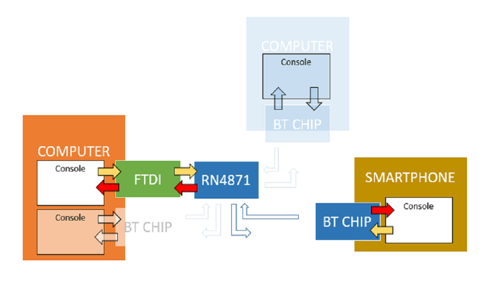
Overview of the network
For this assignement I will try to make communicate several device as shown bellow
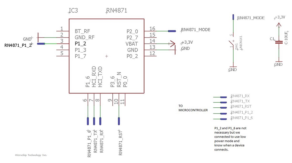
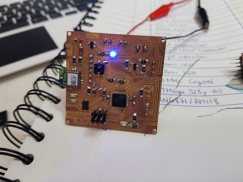
Making the Neil’s board
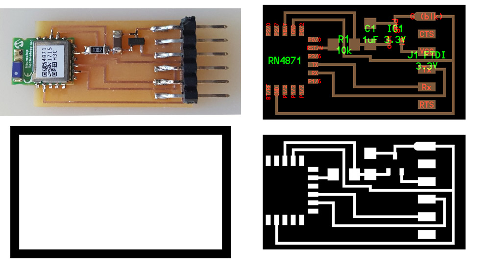
Understanding how the chip works and the pinout.
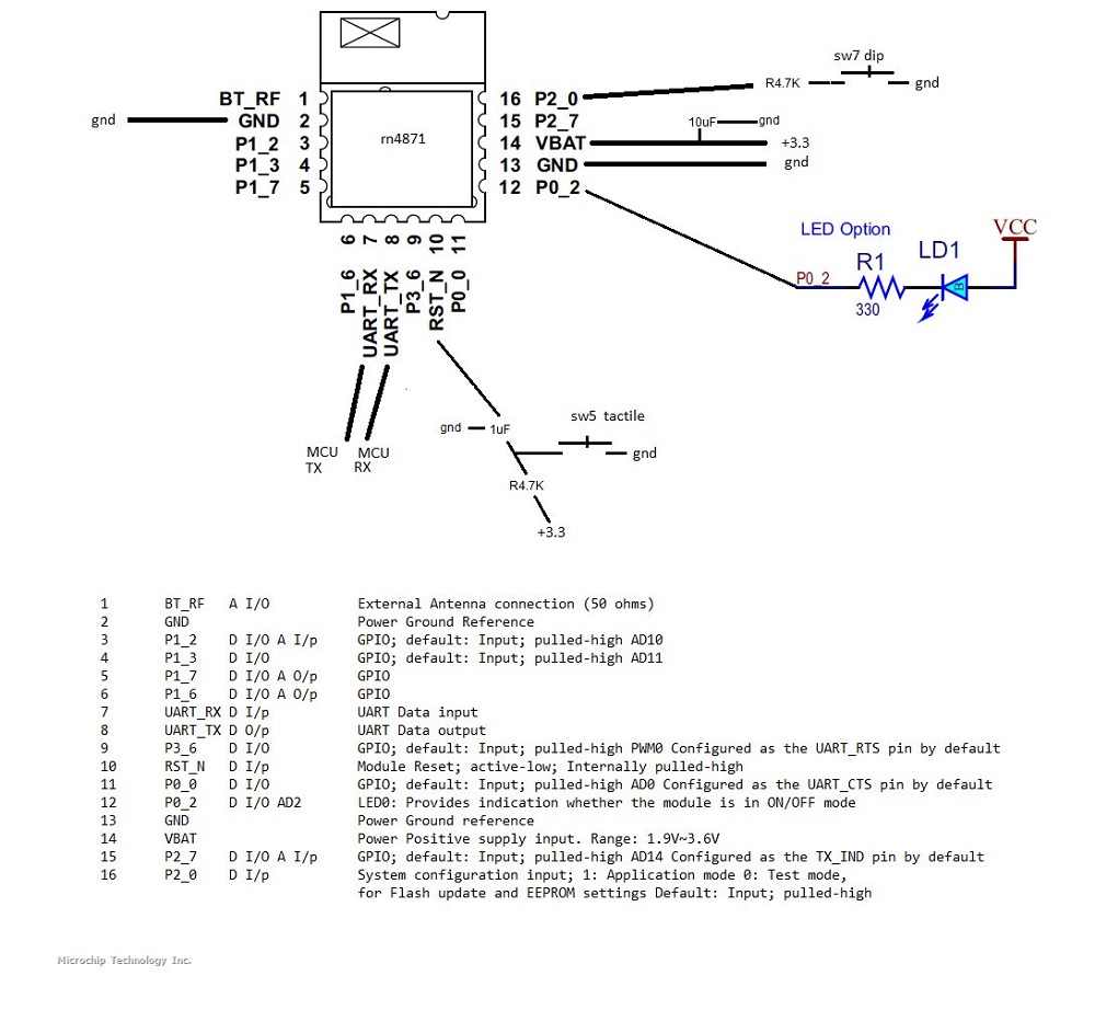
Here are the schematics
Download files to make your own
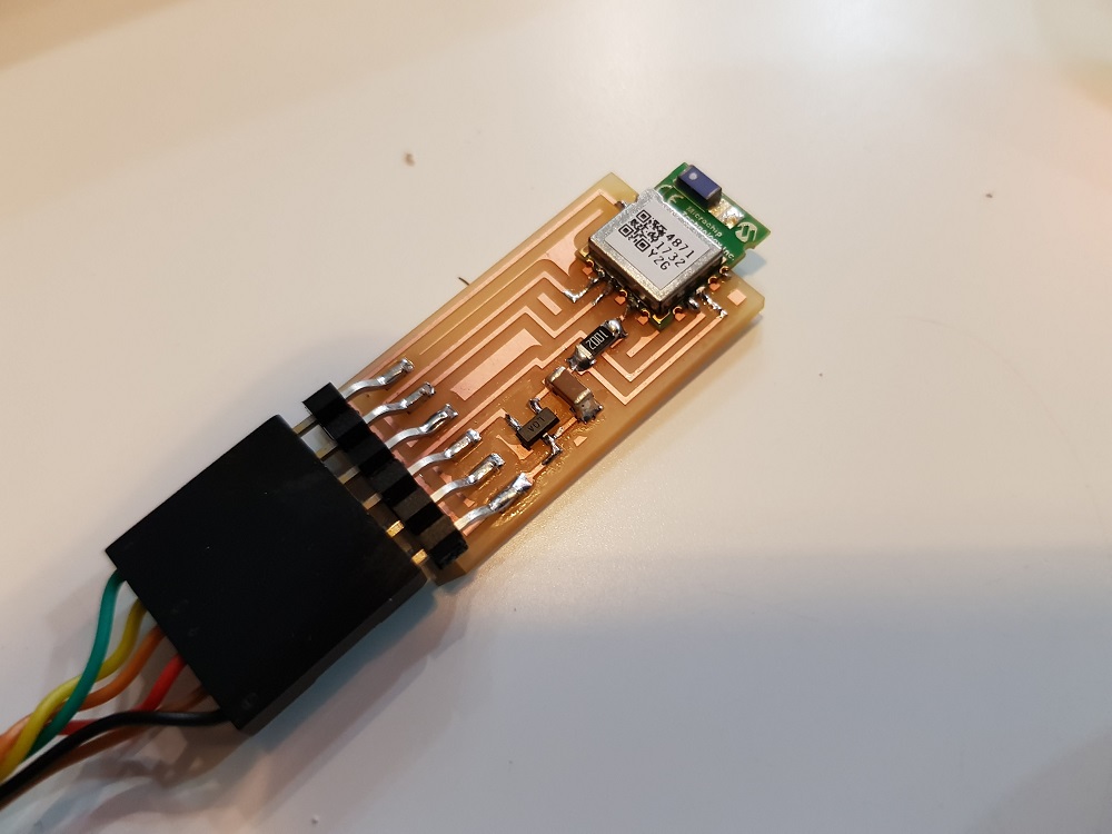
The result after milling and soldering.
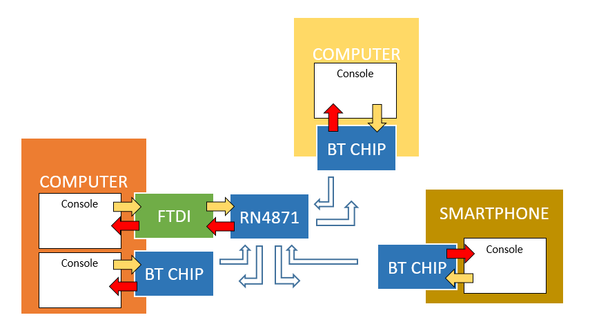
Communication BLE chip through FTDI (serial)
From PC where FTDI cable is connected open terminal
python miniterm.py COM5 115200
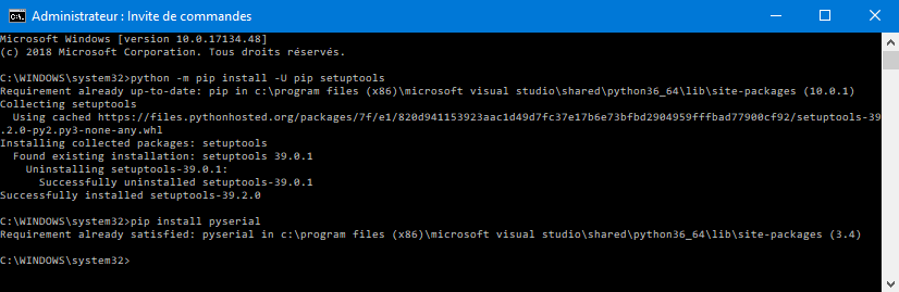
Maybe you have to install pyserial
- type
$$$[ENTER]
a command prompt appears CMD>
-
type
+[ENTER] to turn on ECHO -
type
SS:C0[ENTER] to set default services : Support device info and UART Transparent service -
type
R,1to reboot (need after a set command)
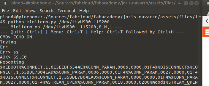
Now the chip is ready is in UART transparent mode, that means that everything that comes from RX will be sent to TX (our serial console)
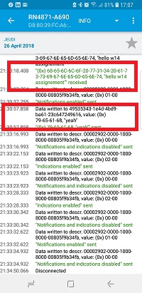
Communication from mobile phone to BLE chip
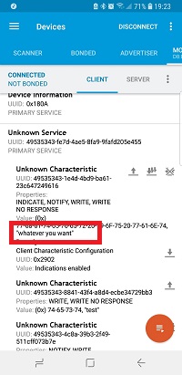
Download and install nrConnect from Nordic into your mobile phone (mine is Android).
Scan for devices and look for rn4871, then connect.
A new tab appears, on client tab, browse the services (remenber we just set the default services)
- click on Unknow Service
- click on Unkwnows characteristics
- You can see 3 icons (1 arrow up, 3 arrows down, 2 arrows up).
- Click on 2nd one (3 arrows down) to turn on notification (disable indications)
communicate from console to mobile
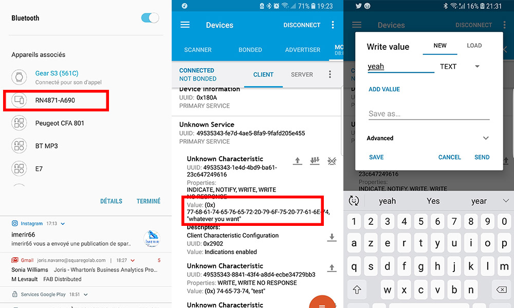
from console, type “whatever you want”, if you type the text you can see each letter, if you copy paste, you will see thos whole text.
communicate from console to mobile
Back from the Mobile phone,
- tap the first icon, the 1 up arrow
- change the data type to text and enter “some text”
- send it
- You can see “some text” in the console.
Conclusion
Finally this it what I did.
but I learn A LOT about how about BLE works and this has to be done for the final project.
EDIT Programming Process from final project
For the final process four parts were involved in a serial bus communication.
PC <-(FTDI)-> ATmega328p <-(UART)-> RN4871 <-(BLE)-> Smartphone
Sofware used
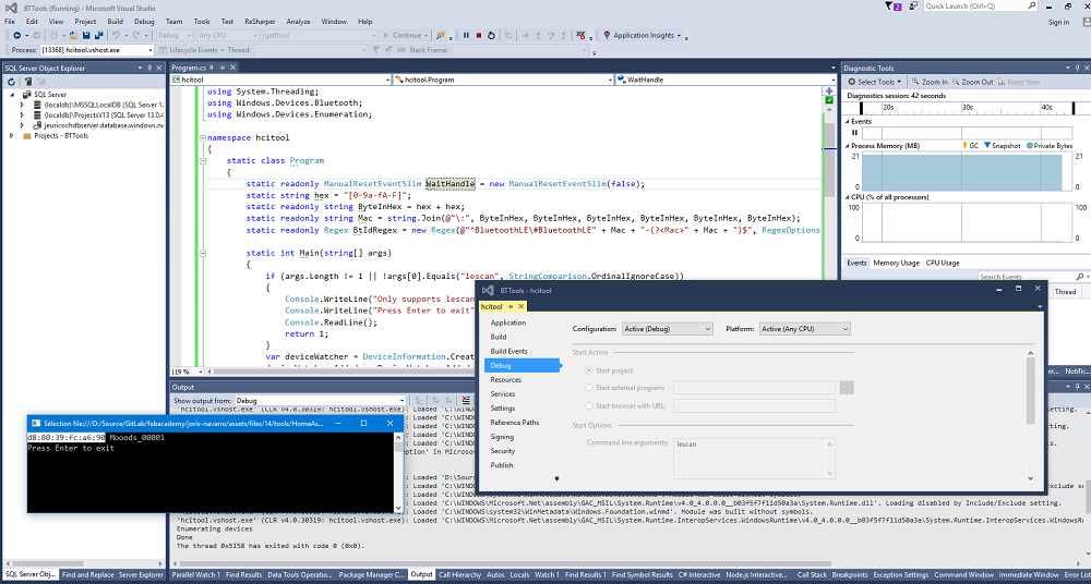
SerialConsole : where commands are sent for the MCU or mobile phone. This instance is used for debugging but we can easily imagine a GUI application to communicate over serial to the MCU/Smartphone.
Visual Studio 2017 for the ATMega Microcontroller : This is the brain, the master, the orchestrator, commands are received from and to PC and / or Smartphone
Visual Studio 2017 - Xamarin.Android for the mobile application : to send commands to the MCU
To communicate all have to respect THE following protocol.
Protocol
There are several ways to process commands from Ardunio, a specific page on arduino documentation present them. Most of them uses libraries. Firmata and Bitlash are the most common, but they’re really more extensive than just having your arduino program talk to your host program.
For the exercice I decided to set up my own protocol that can be describe like this.
Composition of a datagram/packet over serial bus.
- First letter is the recipient address
- second letter is the sender address
- Third letter is the command
- following value is the argument
- \n or \r means end of packet
Addressing
Each node of this “network” has a specific char adress
#define node_id 'a' for the MCU
From Arduino documenation I used the buildin in serial event. In found an excellent documentation from our french friends Reso-nance.
Here is the code used to handle the protocole on the MCU. Basically the code is similar on other devices.
String inputString = "";         // a String to hold incoming data
boolean stringComplete = false;  // whether the string is complete

void setup() {
  // initialize serial:
  Serial.begin(115200);
  // reserve 200 bytes for the inputString:
  inputString.reserve(200);
}

/*
SerialEvent occurs whenever a new data comes in the hardware serial RX. This
routine is run between each time loop() runs, so using delay inside loop can
delay response. Multiple bytes of data may be available.
*/
void serialEvent() {
	while (Serial.available()) {
		digitalWrite(LED_BUILTIN, HIGH);

		// get the new byte:
		char inChar = (char)Serial.read();
		// add it to the inputString:
		inputString += inChar;

		// if the incoming character is a newline, set a flag so the main loop can
		// do something about it:
		if (inChar == '\n') {
			stringComplete = true;
		}
		digitalWrite(LED_BUILTIN, LOW);
	}
}

void loop() {
  // print the string when a newline arrives:
  if (stringComplete) {

    if (inputString.indexOf(node_id) == 0)
    {
      //message is for me !!
      // handle it

      String sender = inputString.substring(1,1);
      String command = inputString.substring(2,1);
      String args = inputString.substring(3, message.length())

      switch (variable) {
        case ‘a':
          // A Stuff, like send commend to the BLE CIP
          	Serial.println("$$$"); // set BLE in command mode
            Serial.println("SS,C0"); // Set transparent UART as default service
            Serial.println("R,1"); // reboot
            delay(500);
        case 'b':
        case 'c':
          // B and C Stuff
        break;
      }
    }

    // clear the string:
    inputString = "";
    stringComplete = false;
  }
}
Click here to download final project full code;
Going further
I am going to use this BLE chip for my final project the network will be composed by a MCU, RN4871 and smartphone and a REST API hosted in the cloud.
I know for this assignement I did not design a board, but I spent the week studying the BLE network neil showed. Then I applied what I learnt for the final project.
Here is a picture of the board designed for the final project that include a serial network smartphone -> BLE -> MCU -> FTDI -> Computer.
Tools:
-
Bluetooth stack for Linux : blueZ
-
Debug Mobile Application : NRF Connect from Nordic
-
also nRF logger to view logs
-
Tools for windows developped by Peter Andersson - Github
Other things I tried… but did not finished
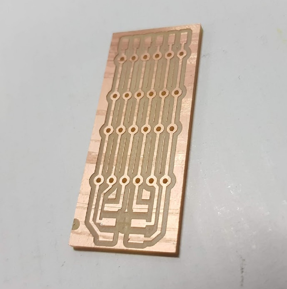
Serial Communication
Then I tried to make one:
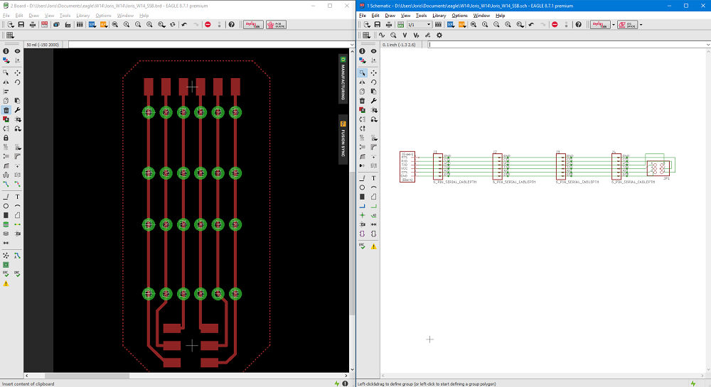
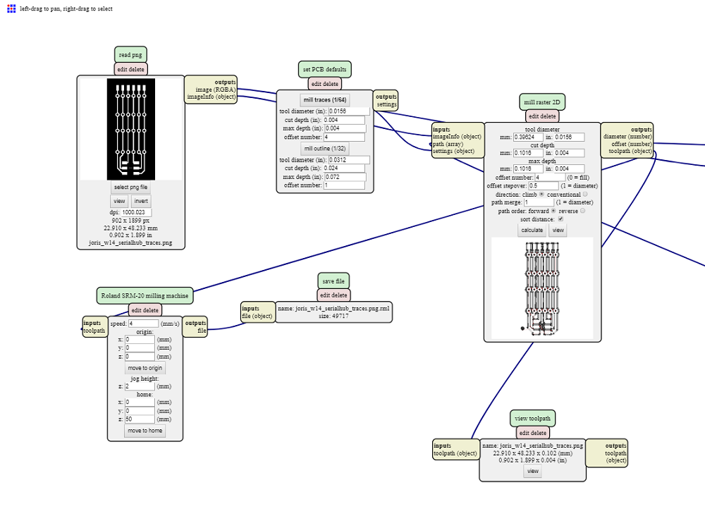
Here is the milled board
to be continued …
I²C
- https://en.wikipedia.org/wiki/I%C2%B2C
- https://learn.sparkfun.com/tutorials/i2c
- https://youtu.be/BcWixZcZ6JY
It’s all about clock:
- Synchonous means share a same clock (SPI, I²C)
- asynchronous (Serial bus)
TWI means Two Wire Interface SDA (Serial Data Line) SCL (Serial Clock Line)
Serial communication is designed to allow just two devices to communicate across one serial bus It is possible to connect multiple devices to a single serial port, but bus contention (where two devices attempt to drive the same line at the same time) is always an issue
Note: if you have 3.3V and 5V devices in the same bus, consider using a level shifter: https://www.nxp.com/docs/en/application-note/AN10441.pdf and http://www.ti.com/product/pca9306
Stay in touch
Hi, I'm
Joris Navarro, from Perpignan (France), a proud dad, a fab director/manager, a teacher, a ceo, a FabAcademy student, but not only. Click here to know more about me.
Check my work for FabAcademy on FabCloud GitLab
@joris.navarro.
Want to say Hi ? Please send me a message.