
Week 03
During the third week of the course we are learning about different kinds of 3D and 3D drawing tools and environments to be used for digital fabrication. You can see the full list of tools discussed on the Fab Academy Computer-Aided Design page.
The assignment for the third week is to use one or more of these tools to design a possible final project. The project of mine is uMap, the miniature projection mapping tool. I will try to create a possible body for enclosing the electronics of my project.
Overview
I am using 2D graphics programs such as Adobe Illustrator, Photoshop and Animate on an everyday basis for my freelance work. I have done 3D work, usually as a part of a bigger project, such as an interactive installation or a device prototype for that. I have studied Maya (before it became a part of Autodesk portfolio), tought myself Blender, recently using mostly Fusion 360 and being interested in Antimony.
I forgot most of Maya by not using it; realized that Blender is great for artistic projects, but not so much for precise CAD drawings. Fusion 360 is great for precision and provides with fabrication tools, such as toolpath generation for CNC machines and *.stl export, although it is cloud-based and there is a valid concern that it can become too expensive to buy and all my projects remain on Autodesk servers if I fail to pay them. An open source alternative for Fusion 360 might be FreeCAD.
Antimony seems very promissing. I love node-based environments, even more if you have the possibility to build your own nodes. With Antimony you can store your project files wherever you decide yourself, as a tool it is free and open source. Thanks Matt Keeter. There is another interesting (more recent) project by Matt Keeter which is called libfive. It is a software library and a set of tools for solid modeling. It includes a graphical user interface called Studio, which looks very similar to OpenSCAD. Libfive looks with its Studio are the most recent projects of Matt Keeter and probably include many learnings from the experience of building Antimony.
To conclude this introduction and cast a foundation for my CAD explorations this week, I have decided to explore the parallel universe and improve my existing skills. Therefore these are the tools I would like to use to try to design parts for my uMap project.
- Antimony
- Libfive
- Fusion 360
- FreeCAD
Before I dive in, check out the CAD overview slides by Ferdinand Meier. His presentation provided with a valuable insight into the world of present-day CAD software.
Antimony
I started out with a simple test to model a base surface with pads for connecting a possible covering part in the future. Following is a description on how it went.
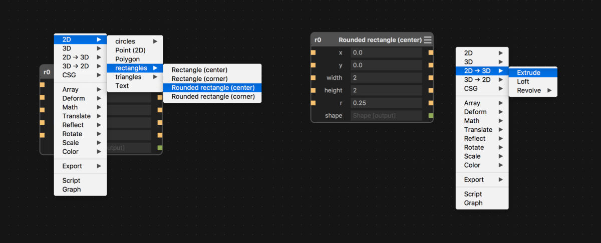
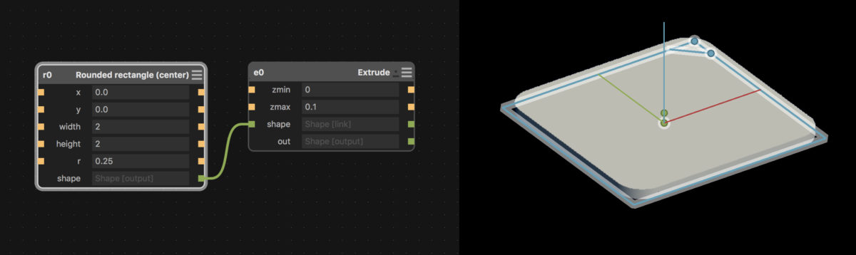
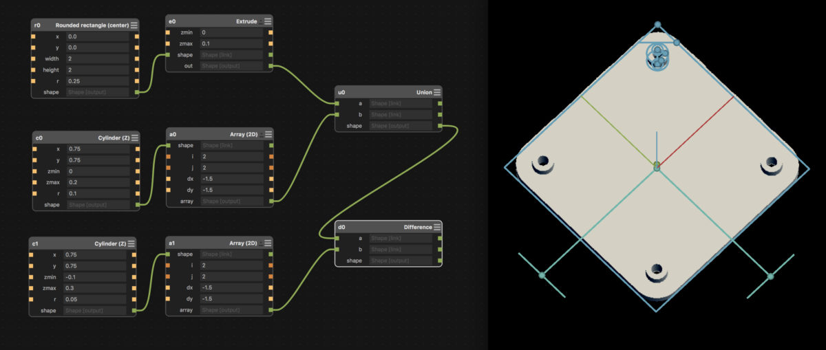
First, I created the base structure, by using the Rounded rectangle and extruded using the 2D→3D Extrude option.
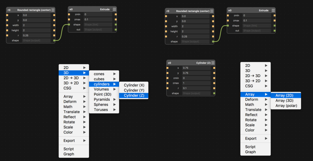
Following that I created improvised cylinder-shaped pad and made 4 copies of it by using the Array 2D function.
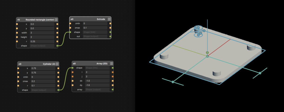
Next, I merge the pad cylinders with the base by using the Union CSG operation. I make a copy of the pad cylinder and array functions, decrease the radius of the copy cylinder and make it longer (like a drill). The CSG Difference operation let me use the longer cylinders as drills to make holes in the base structure with pads.
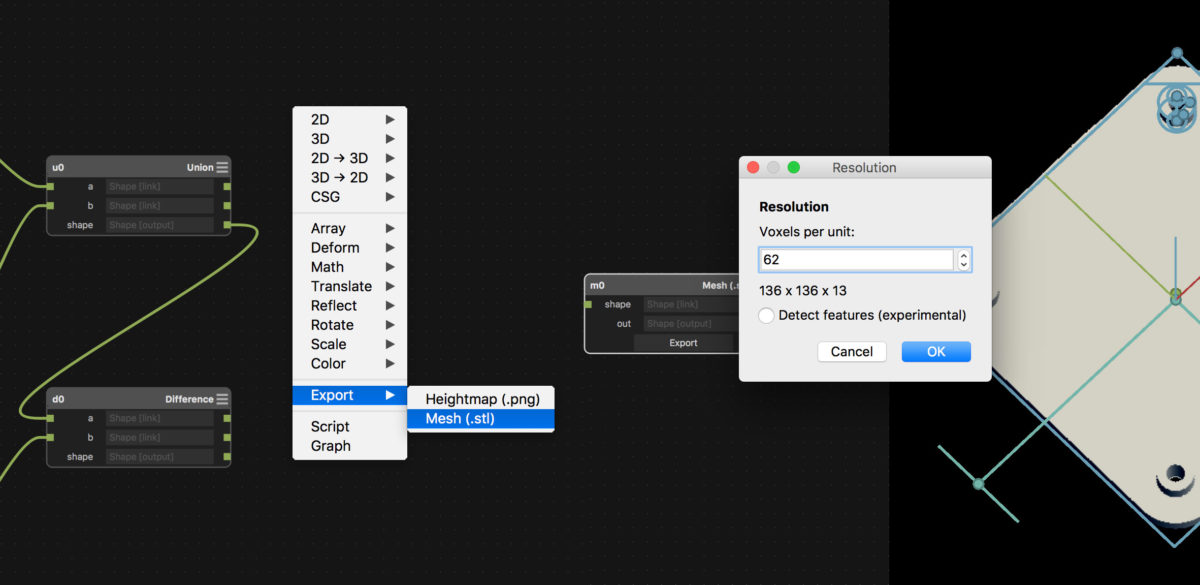
Next possible step would be to 3D print it, thus I will try to export it as a STL file. 62 voxels per unit is the recommended value by Antimony. From my further explorations, that is the resolution of the generated triangle-mesh of the form.
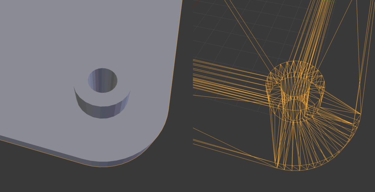
To examine the resulting model, I will open it in Blender and take a closer look at it.
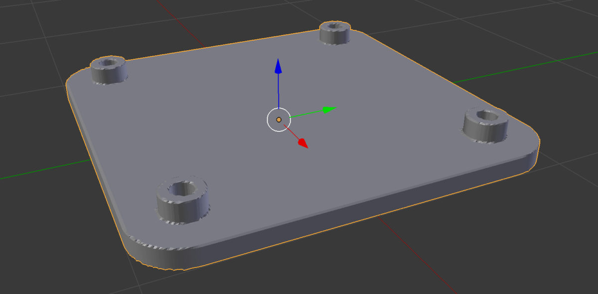
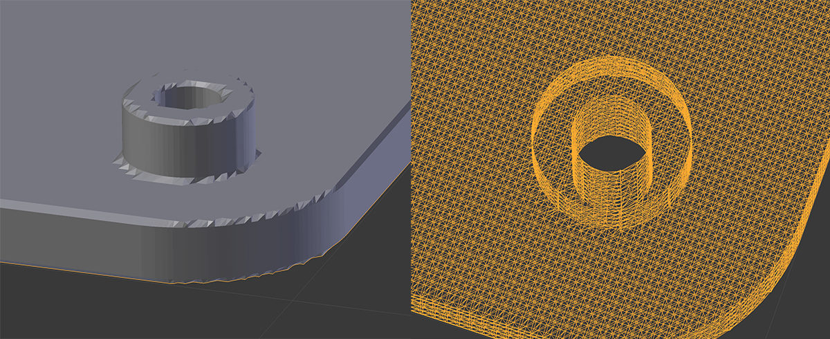
As you can see, the way mesh is generated in Antimony is very specific. Here you can see what the voxels per unit measurement actually means. Antimony uses an approach similar to the one of ray tracing in 3D rendering software; it hits the underlying mathematical model with voxels and checks if it is inside or outside of it. Based on that the STL exporter makes a decision on how to build the mesh.
Libfive Studio
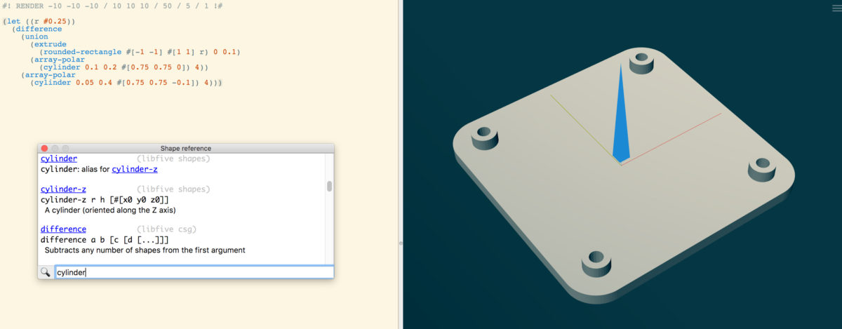
It took a bit of time to understand where to start, but since I had some previous experience with OpenSCAD, it did not take more than 30 minutes to finish my first extrusion, union and difference operation. The code below is all you need to create the same model I did with Antimony before.
(let ((r #0.25))
  (difference
    (union
      (extrude
        (rounded-rectangle #[-1 -1] #[1 1] r) 0 0.1)
      (array-polar
        (cylinder 0.1 0.2 #[0.75 0.75 0]) 4))
    (array-polar
      (cylinder 0.05 0.4 #[0.75 0.75 -0.1]) 4)))
Libfive Studio has a neat Shape reference window and it is not that hard to find the things you need if you have some CAD and programming background. It took some time to understand how to define my own variables, but I got there by examining the example projects.
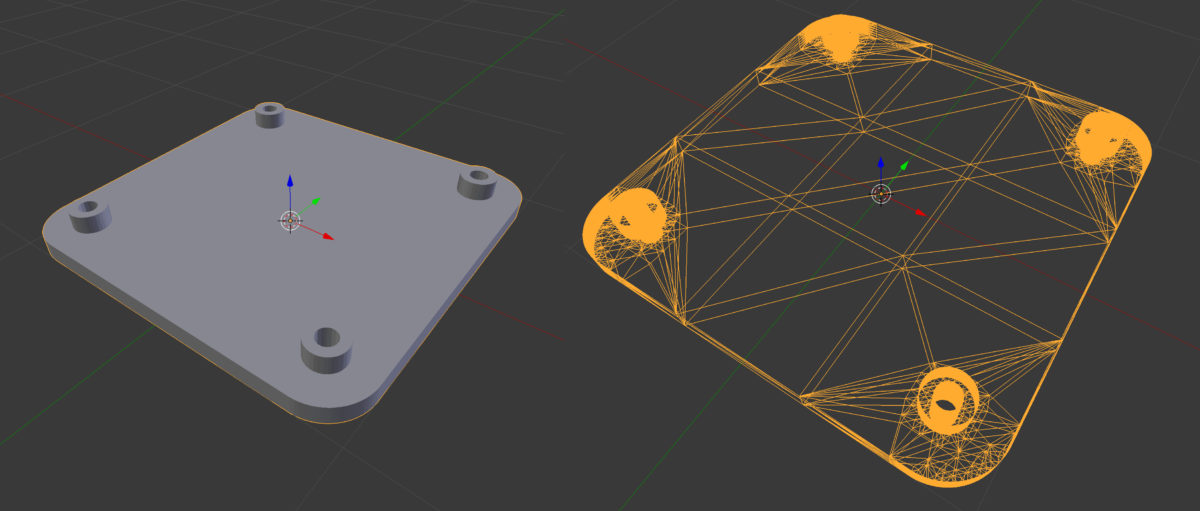
It looks nice in Studio, but how about STL export and Blender? Below you can see how Studio generates mesh on STL export. It does not ask you to provide voxels per unit when exporting. As it is said on the libfive GitHub page, a great deal of work has gone into the meshing algorithm, which produces watertight, manifold, hierarchical, feature-preserving triangle meshes. You can see how it works in the images below.
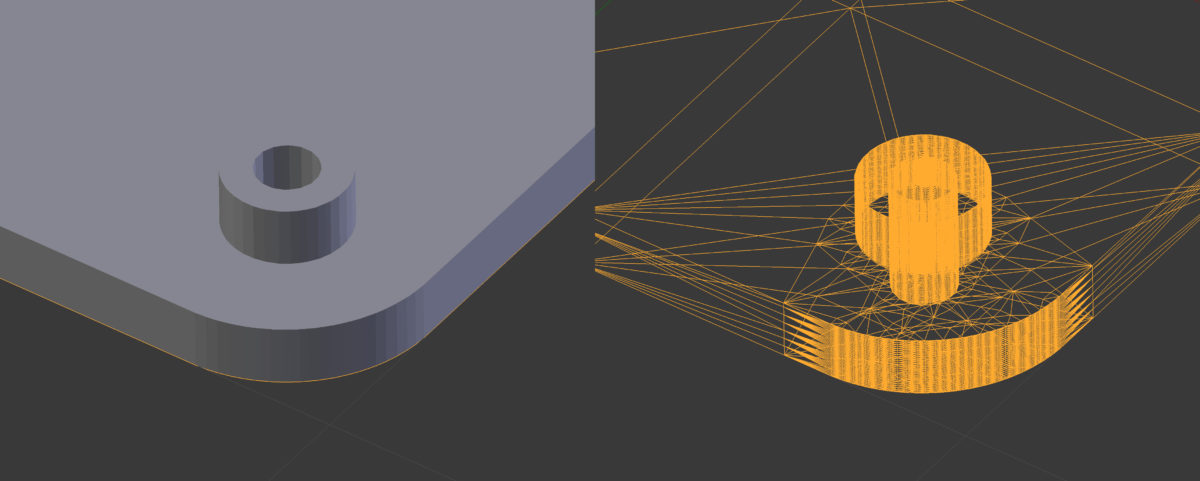
With that said, it is highly possible that libfive Studio is something I will consider using for my full design. It plays well with Git, as one has to treat the designs as plain text source code, not proprietary and rather bloated project files.
Fusion 360
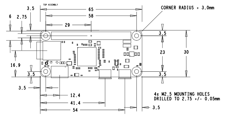
As I have done designs with Fusion 360 before, I consider it something that I already know, thus I will use it to build the first draft of the uMap case. Before I start, I need to get measurements for the electronics that I will put inside. I will have two main parts.
Below are an image with both.
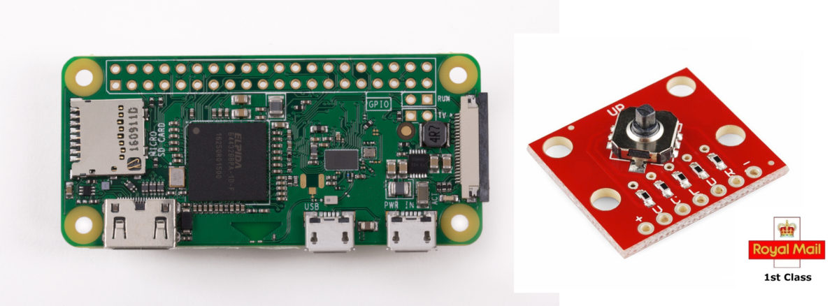
Here you can see the measurements of the Raspberry Pi Zero W.
And measurements of the tactile switch.
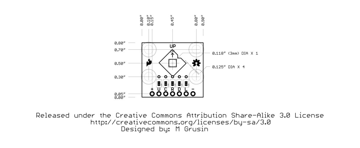
As you can see, I did not have to measure the parts myself, you can find all the numbers needed on the internet. I will start out by creating the two parts as basic solids in Fusion 360. I then will use the solids to build around them.
I will not proceed here since I kept using Fusion 360 for almost all the following assignments.
FreeCAD
I have heard about FreeCAD from my CAD friends, but only one of them was truly excited about it. I always wanted to try it out, as my long-term mission of migrating from Mac OS to Linux has to be accomplished at some point, and I would like to be able to jump right into it with knowledge about the tools that I can use there.
It took much longer to create the same part with FreeCAD as with Antimony and libfive Studio combined. The interface is not too responsive and it creates a feeling that the application will crash any moment and take your carefuly crafted design with it to the upside down or similar.
Nonetheless I managed to create a parametric design in a bit less than 2 hours. You can see the full image of it and the parameter spreadsheet below.
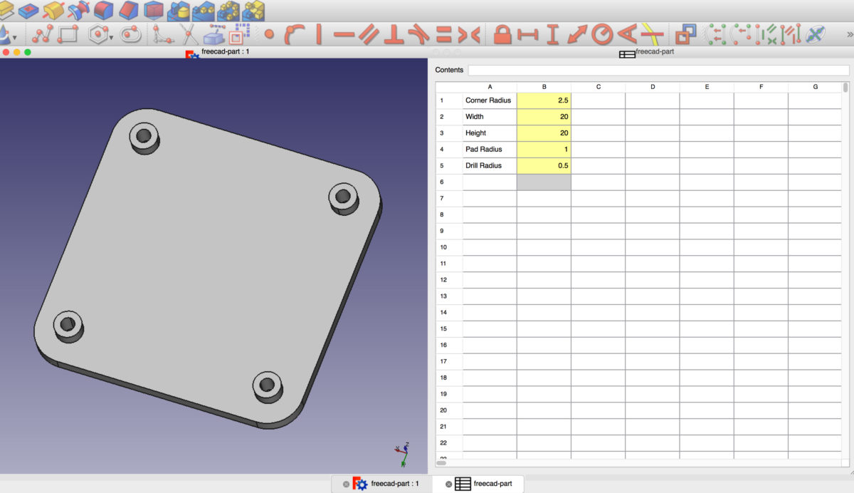
Trying to find tools to accomplish what I want, I jumped onto many interesting features, such as OpenSCAD integration and WebGL export. Even thugh the user interface needs a lot of improvement, the promissing functionality that I found, triggered my interest.
As with the other tools mentioned on this page, I tried to export a STL file and open it in Blender to examine the mesh. You can see the images below.
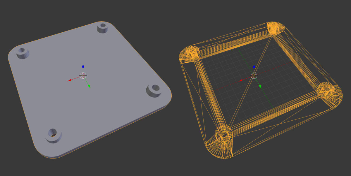
As one can see, the mesh export works as efficient as the one of libfive Studio. Also, it seems that FreeCAD has more functionality than I would actually need at the point.
Preparing PCB Files for Mods with Adobe Photoshop
Adobe Photoshop is a part of the Adobe Creative Cloud package and integrates well with other parts of it (software as Illustrator, After Effects, Premiere). I use Photoshop on everyday basis for my personal freelance projects. During the Fab Academy I mostly use it to crop and resize images for the documentation website.
Here I will add something different. Recently I figured out how Photoshop can be used as a step in-between Eagle and Mods to create .png source files for Mods for milling traces, drilling holes and contours. Let’s begin.
First step is to export a monochrome .png image from Eagle. To do that, go to Eagle and select File → Export → Image. Select monochrome and enter 500 in the dpi box as in the image below.
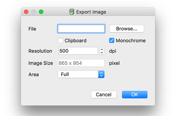
Click on Browse, choose a place on your file system where you can navigate later to pick the image up. Hit OK to create the image.
As the next step, open the image in Photoshop and as the first step here change it’s color mode. Choose Image → Mode → RGB Color even though we are going to use pure white (#ffffff) and pure black (#000000) only.
If you do work on a retina Mac like I do, make sure that Eagle did not export the image 2x bigger than you expect.
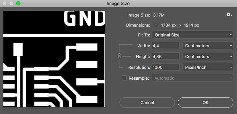
To do that go to Image → Image Size and change the units to millimeters. See the image below.

In my case the image is obviously bigger than expected, it should be 32.39mm (not including the random whitespace Eagle adds when exporting). The numbers in the Image Size box are clearly 2x bigger than I expect.
To fix that, uncheck the Resample checkbox and change the Resolution to 2x the one you have. In our case it is 500, change it to 1000. This will preserve the crispness of the drawing as it will not change the pixel array of the image.
the next step, which is tracing the outlines of our board by hand by using the Pen Tool. Hit the P key to activate it. Set the type to Pixels and color to pure RGB white (#ffffff). Begin tracing your outline by pointing and clicking.
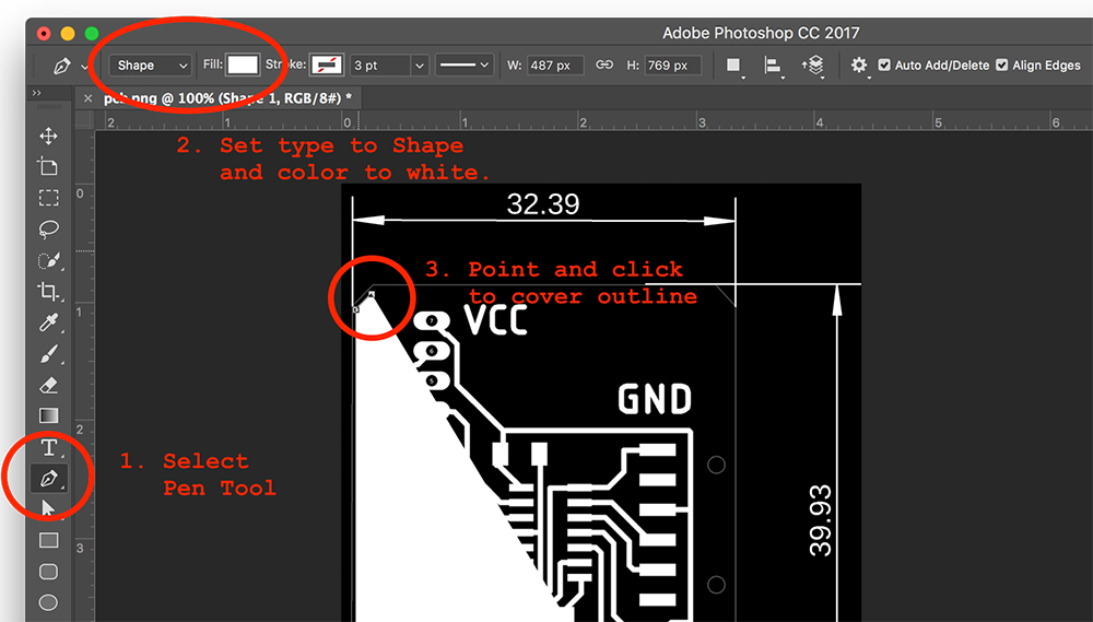
This is going to create a new layer in the layer panel. Rename it to something meaningful (contours will do, since later we are going to add a background layer).
Next we will take care of the drilling holes. In mods, everything that is white, is sacred. Toolpaths are generated only where there are black pixels. With that in mind we can use the mill outline (1⁄32) preset to drill holes where there are black spots in the image. In fact it is pocketing, not driling. This approach lets us to create holes in many different sizes by using the same tool as for milling the outlines.
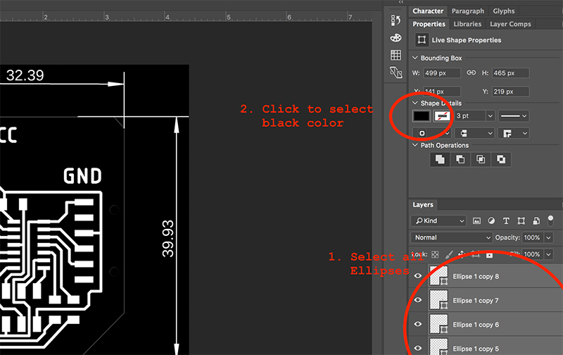
Select the Ellipse Tool by hitting the U key. Set the color to something bright first to be able to tell if the circle overlaps the hole. Start drawing circles. Press and hold shift while drawing to be able to draw a circle instead of an oval.

Copy this circle to cover all areas with the same size. Draw new ones where the size is different. Then, in the layer panel, select all and change their color to pure black (#000000).
Now we can group all the circle layers by hitting Cmd + G. Rename the group to something meaningfull again, holes will do fine.
Now we have to tweak the original image to get our traces layer right. Make a copy of the original PCB image layer from Eagle, rename the layer to traces.
Use the Polygono lasso tool to select the area that we want to keep. Then go to Select → Inverse to invert the selection and hit the DELETE key. This will remove all the pixels we do not want to be used for milling our traces.
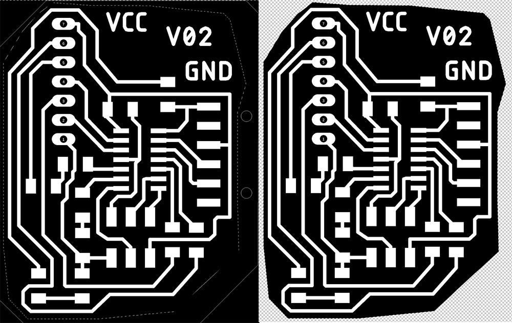
The image above shows how the image looked like before and after the deletion of the outer area.
Use Crop tool (C key) to crop the image to match the dimensions of your PCB design.
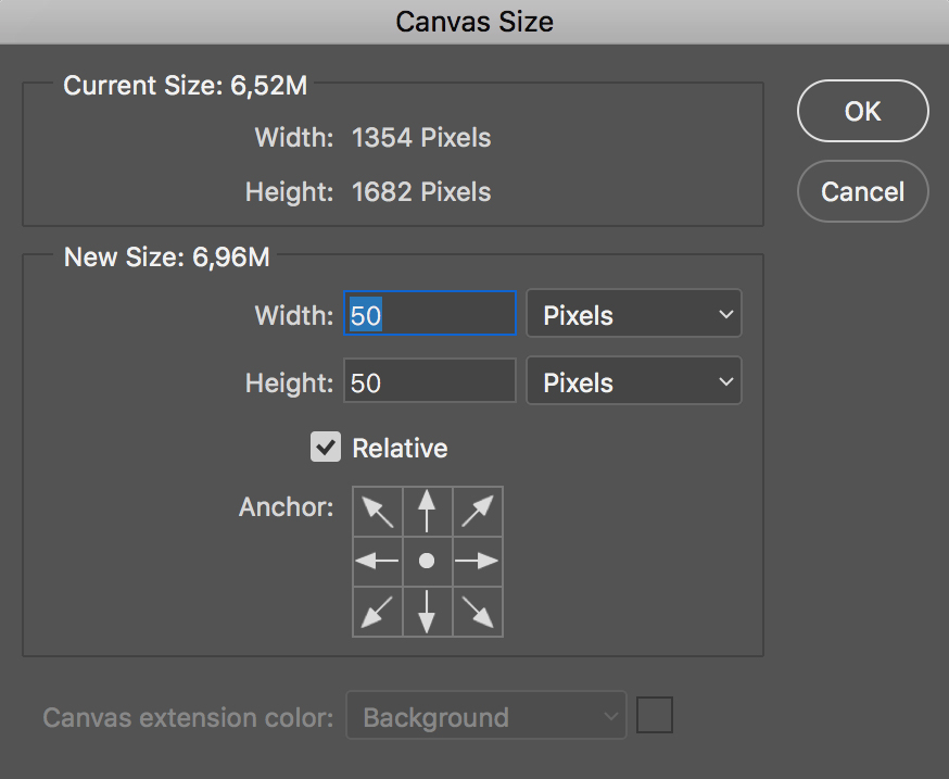
Before adding the background layers, we need to expand the bounding box of the image to add a bit space around (needed for Mods). Go to Image → Canvas Size and do the following.
- Set the Anchor to the center.
- Select the Relative checkbox.
- Change the units to pixels.
- Enter 50 for both, Width and Height (this will add a 25px margin on all sides) .
- Hit OK
Now we have to add background layers for each of our steps and tidy up our project file.
- Start by adding a black (#000000) layer under the contours layer.
- Add white background layer under the holes layer.
- Lastly add another black layer under the traces layer.
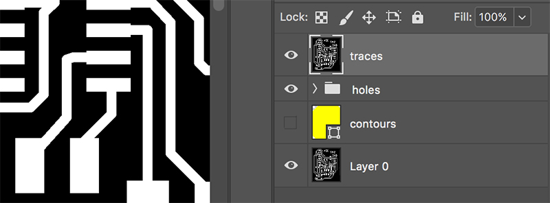
Group related layers together by using the Cmd + G key combination. Your layer structure should look as in the image below now.
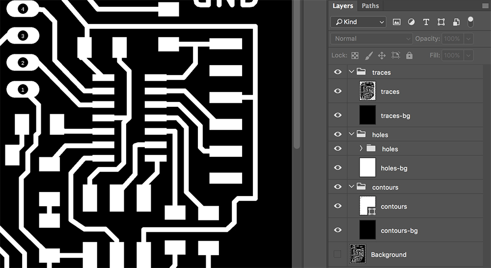
Now you can hide and unhide the groups to cover and uncover the Mods input image you need to export.
To export the image for mMods, do the following.
- Hide all groups and unhide the one you need.
- Go to File → Save As.
- Set Format to PNG.
- Choose a safe place on your disk and the name of the file.
- Hit Save.
- PNG Options will pop up: hit OK.

The image will be saved as a copy. Make sure you save your Photoshop file somewhere also. Here is mine. Now you are ready to import the image into Mods. This you know already. Thank you for reading and happy milling!
Conclusions
After refreshing skills in Antimony, Fusion 360 and trying out libfive Studio and FreeCAD for the first time, there are some things that I picked up on the way, that would be interesting to try out or refresh in the near future. One of them is OpenSCAD and the second–LibreCAD. Also BRL-CAD is something that seems like worth looking into.
OpenSCAD has a history and I believe that the age of it matters. Early open source 3D printers have been made in OpenSCAD, in the near future I do not plan to make anything more complicated than that.
LibreCAD might be useful in scenarios where I would need to create a detailed 2D drawing for machining something very specific or with a machine that is accessible only by certified personel within a company. The language of a CAD drawing would be an important thing to learn as well.
BRL-CAD, the following quote from its website leaves without any further questions. BRL-CAD is choice of U.S Military. For more than 20 years, BRL-CAD has been the primary tri-service solid modeling CAD system used by the U.S. military to model weapons systems for vulnerability and lethality analyses.
You can see mostly free and open source tools discussed on this page. After exploring the options above, I realized that the functionality of the freely available open source tools is more than enough for my current and near future needs. I would still keep using Fusion 360 as one of the potential mega-tools of the future.