
Week 08
During the Week 08 we had to explore the possibilities of computer-controlled machining. In our case it meant gaining understanding about the terminology and available machines involved. The individual assignment was about making something big. You can find more information about the week on the Fab Academy class page of the week.
Below are some notes from the lecture. Not much, but still.
Kerf - material being removed
Runout - how much does the tool jiggles around
Conventional and Climb machining, related to tool rotating direction
Milling at the Fab Lab BCN
RhinoCAM is the preferred software for CAM at Fab Lab BCN. In order to use it, you have to type RhinoCAM2015 in the command line of Rhino and hit ENTER. You can use DXF file format with RhinoCAM.
Make sure that you are in the MILL module.
The strategies that we are going to use this week are the 2 Axis strategies. One might ask why 2 axis for X, Y and Z? It is because Z is not considered as an axis in this case.
Facing or Roughing is used to flatten the top layer of the material.
Pocketing is for creating pockets, or pits in other words, into the material. One can create things like boxes or cups by using this strategy.
Profiling is used to follow a vector line in order to cut something. You can position the tool on one side of the line (similar to tangent contstraint in CAD).
Engraving is similar to profiling, but insdead of movig the tool on one side of the line, the center of the tool follows the line.
V-Carving relates to tools that have a V shape. It is useful for cuts that have to be in an angle. It is also useful for engraving text. Nice for creating decorative cuts that employ depth and shadow-play.
Hole Pocketing is used to create holes. It is similar to Pocketing, but does not leave material on the bottom. It cuts as deep as the defined material thicness.
Hole Profiling creates holes, but instead of using the pocketing / engraving approach, it cuts the pieces out by using their outlines. It is important to use tabs for this strategy.
Add tabs to pieces that will be cut out from the material in order to avoid excessive amounts of panic!
Tabs keep the pieces to be removed in place while cutting your material. You would cut the tabs after the milling machine has finished its job. You would use a hammer and a chisel or a handsaw to do the final cuts. If there are no tabs, the piece can get loose, jump off and destroy your lab!
Click on Post to open the Post Processor Options window. ShopBot MTC post processor has to be used for the ShopBot milling machine. Mach3MM post processor has to be used for the Precix machine. Go to Fab Lab BCN Wiki to learn more.
Post File Extension has to be set to .sbp.
Click on Stock to specify material that we are going to use for milling.
You can import 3D objects from other 3D software, but you have to make sure that the top surface matches the Z axis origin (value 0).
Creating the stock usually involves creating a new Box Stock instance. The origin of the Box Stock should be set the top-left corner of the box representation.
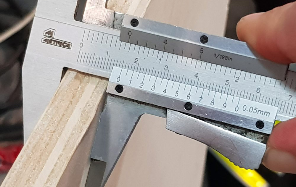
Measure your material before creating the stock instance.
Stock from selection can be used as well. You can define your material by drawing in the 3D view. You can extrude the outline downwards in order to define the material thickness. When you are done, click on Stock and select Stock from selection.
Click on Stock visibility icon to enable a ghost image of your material. You can delete the original object, the stock ghost will be still there.
You should position the bottom-left of the material at the X0, Y0 position of the 3D view.
It is important to mark where you are going to put the screws for attaching the material to the build plate of the milling machine.
The first CNC strategy is going to be for the screw marking. Add single points to mark the places where you want to add screws. If you skip this, you have a higher possibility to break the tool as it hits the screws. You (and the machine) should know where they are.
Holes/Drill can be used to mark the skrew locations. Select the points which define the drilling locations.
Tool selection lets you define parameters for the tool you are using.
The less flutes your tool has, the faster you have to go in terms of RPM.
Search: ShopBot chip load. Use GUHDO chipload calculator (scroll down to the bottom of the page).
You can also use the official ShopBot chip load guide or consult the Fab Academy Barcelona CNC tips.
Clearance is the tool traveling distance above the material when rapidly changing location. It is important to set it if you use attachments that stand out above the material.
We are going to do most tasks with a 6mm tool. First steps are the following.
- Put the material on the build plane of the machine.
- Set the origin of the milling machine.
- Use the screw marking strategy.
Dogbones are additional interior corner cuts for connecting parts. Dogbones one has to define herself for interior corners of connecting parts. Since the tool of a milling machine is circular, it is not possible to create sharp interior corners otherwise.
The not recommended, but fast way of creating dogbones is to define points on a separate layer in RhinoCAM and create a drilling strategy from them.
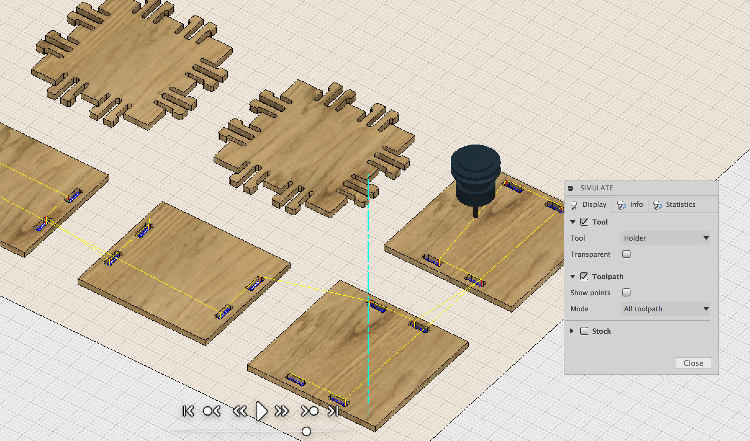
Hit the Play button to preview the simulation of the created strategies.
To create a strategy, you have to select one or more paths in your design and then choose a strategy template from the Program menu. A window will open and you will have to define additional parameters.
Cut Parameters define how the tool should move along the line and in what direction it should spin. In Global Prameters you can specify such parameters as Tolerance which specifies what is the maximum distance of the interpolated line from the actual vector toolpath. Region refers to the path that we are selecting in RhinoCAM’s design.
Cut Levels you hace to specify At Top for the Location of Cut Geometry. Add 1mm more for the Total Cut Depth in order to make sure that the tool cuts through.
You can do most things with Pocketing, Engraving and Profiling.
It is good practice to create your paths using layers. Create one for marking, engraving, pocketing and profiling. That let’s you to select all paths that you want to relate to a strategy at once. The more parts you have, the more time and effort you can save with this.
The range of the Spindle Speed is from 6,000 to 14,000 RPM (rounds per minute). Feed Rate unit is millimeters per minute. 3200 mm/min is a good start for a 6mm tool with 12,000 RPM.
There are two cutting modes. Sometimes we might want to go slow at the end of a cutting strategy. Rough Depth refers to the depth we want to cut fast or rough. Finish Depth refets to the depth that we might want to cut slowly in order to reach highter cut quality. For each cutting mode we can specify depth cuts. For a 14mm rough cut we might specify 7mm depth cut step which will result in 2 cuts. For 2mm finish cut we might choose 1mm depth cut step and end up with 2 finishing cuts for the last 2mm of the material.
Rough Depth Cut should be less or equal to the diameter of the tool. For the Finish Depth Cut it should be generally less than the diameter of the tool.
Do not forget to add tabs to your profiling strategies!
Advanced Cut Parameters is the place where you can find
Tools Machining Options click on Regions in order to define paths that will have custom tabs. Create a new region and use the Manual Bridge Points on selection tool to add custom locations for your tabs. Then in the Control Geometry part of the strategy parameters, select the Select Predefined in order to select the predefined region with manually added tabs.
Select the strategies you want to export, right-click and select Post to generate continous machine code for the selected strategies.
Add a number in front of the strategy file to be able to tell the sequence of the strategies you want to run.
Below is a YouTube video that can help to understand most of the things discussed above.
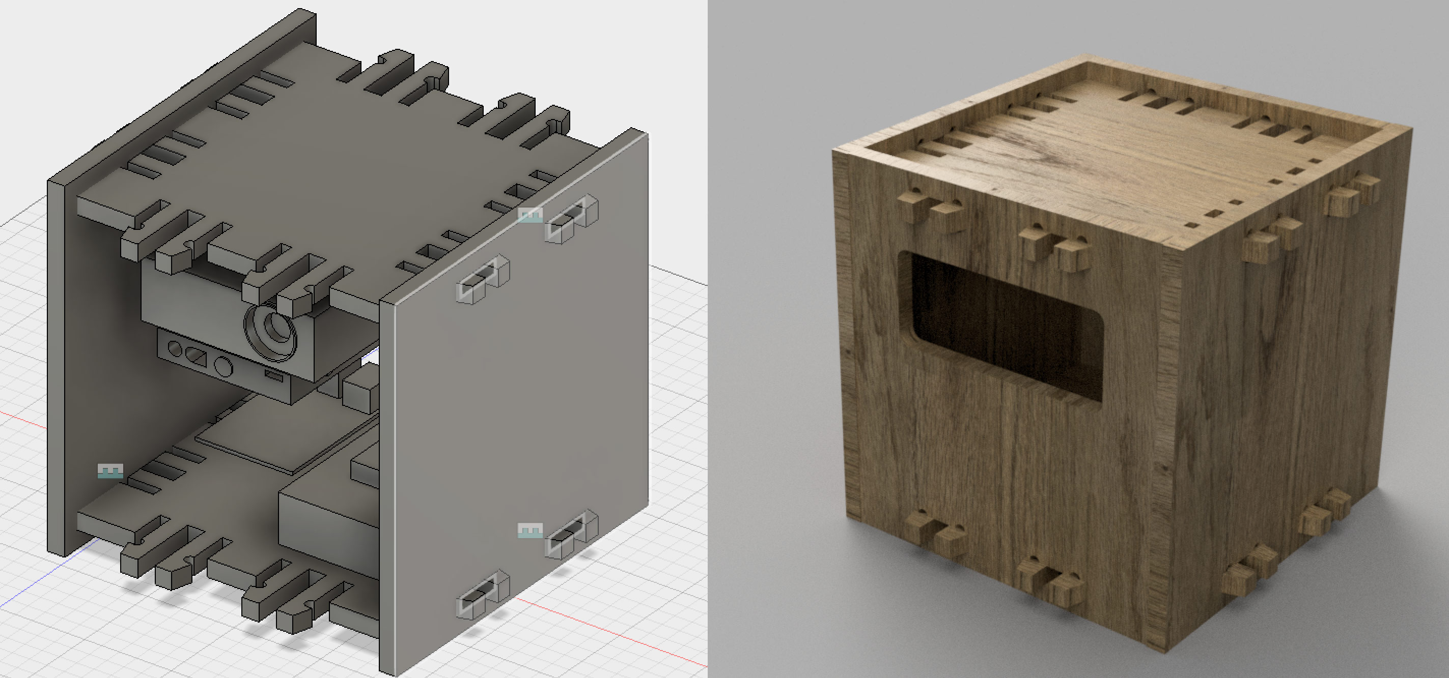
Creating the Projector Box
As my individual assignment I am going to create a projector box for my upcoming Radical Projection Mapping Lab workshop. There are several constraints that define the success condition of this project.
- The box has to be easy to assemble and disassemble.
- All the electronics parts and the Dell M115HD mini-projector has to fit in the box.
- The parts for 6 boxes should fit into a check-in luggage bag.
- The parts for 6 boxes should weight no more than 10kg.
Design in Fusion 360
I did two design iterations. For the first one I went with the knowledge I already had and stopped at the point where one would generate toolpaths for the milling machine. The design was partly parametric and I felt that things could be done better.
Before doing the second iteration, I watched the Bookshelf Tutorial by Patrick Rainsberry; he demonstrates how to create a bookshelf in Fusion 360 and prepare it for milling on the ShopBot. I learned a few tricks to improve my workflow. First of all: using a single profile sketch for most of the basic parts was the most important thing that I learnt. Creating sketches on surfaces on-the-go is another thing.
In the first design I designed each part separately and then did the assembly to check if parts fit. For the second one I would design the box as if it would be assembled already and then lay the parts out on the virtual build plate.
Setting parameters is an important thing so that we can potentially adjust things for every next iteration. Below is a list of parameters I decided to create.
- ToolDiameter
- MaterialThickness
- SpringThickness
- SpringShoulderLength
- Kerf (extra space between fitting parts)
- BoxSize (width = height = depth)
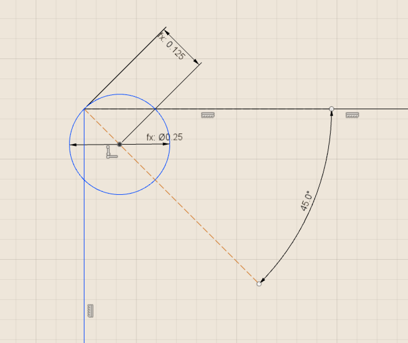
I did not use the plug-in dogbone approach from the tutorial video since I wanted to have more control over where the dogbones are. Sketching them and cutting them with the extrude tool seemed a better way to go for me. I used the Prepping your model for milling article by Adam Stein to figure out the best way to make custom dogbones. Below is what you have to do.
- Create a construction line from one of the corners of your pocket sketch.
- Make a 45deg angle between it and one of the edges.
- Draw a center diameter circle on the line.
- Adjust the circle diameter to match the CNC tool.
- Create a dimension between the center of the circle and corner of the pocket (the same one where the 45deg construction line is attached).
- Repeat the previous steps for each of the corners.
Humans are generally lazy and one may ask, how to repeat the operation with the least possible effort. There is a way. For that you have to make sure that you have set up two construction lines.
- A vertical one that splits your pocket in half horizontally.
- A horizontal one that splits your pocket in half vertically.
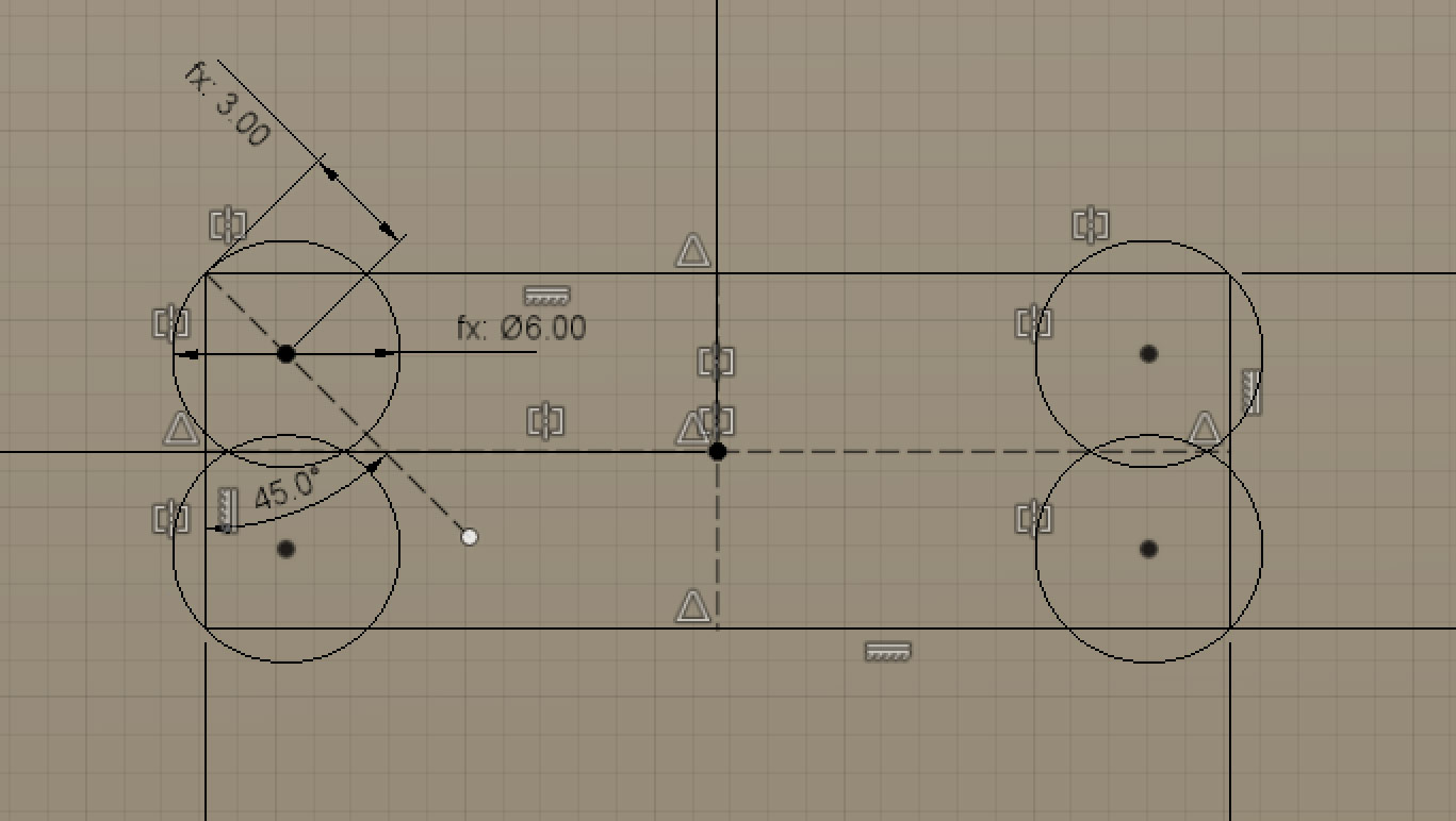
Then use the Sketch → Mirror tool to mirror the dogbone circle around the vertical midline. Confirm success, use the Sketch → Mirror tool once more, this time select both circles and use the horizontal midline to mirror both of them. For this to work you also need to make sure that you have positioned your pockets by using the center point of them. The dogbone circles will snap to the corners of your pocket.
If your design is symetric, you do not have to create every dogbone pocket separately. Do a cut extrusion in the surface you want to have the pockets, use Create → Mirror tool to mirror the extrusion around a midplane created by using the Construct → Midplane tool. Use the Create → Pattern → Circular Pattern to copy resulting tabs by rotating them 90deg around center axis of the box.
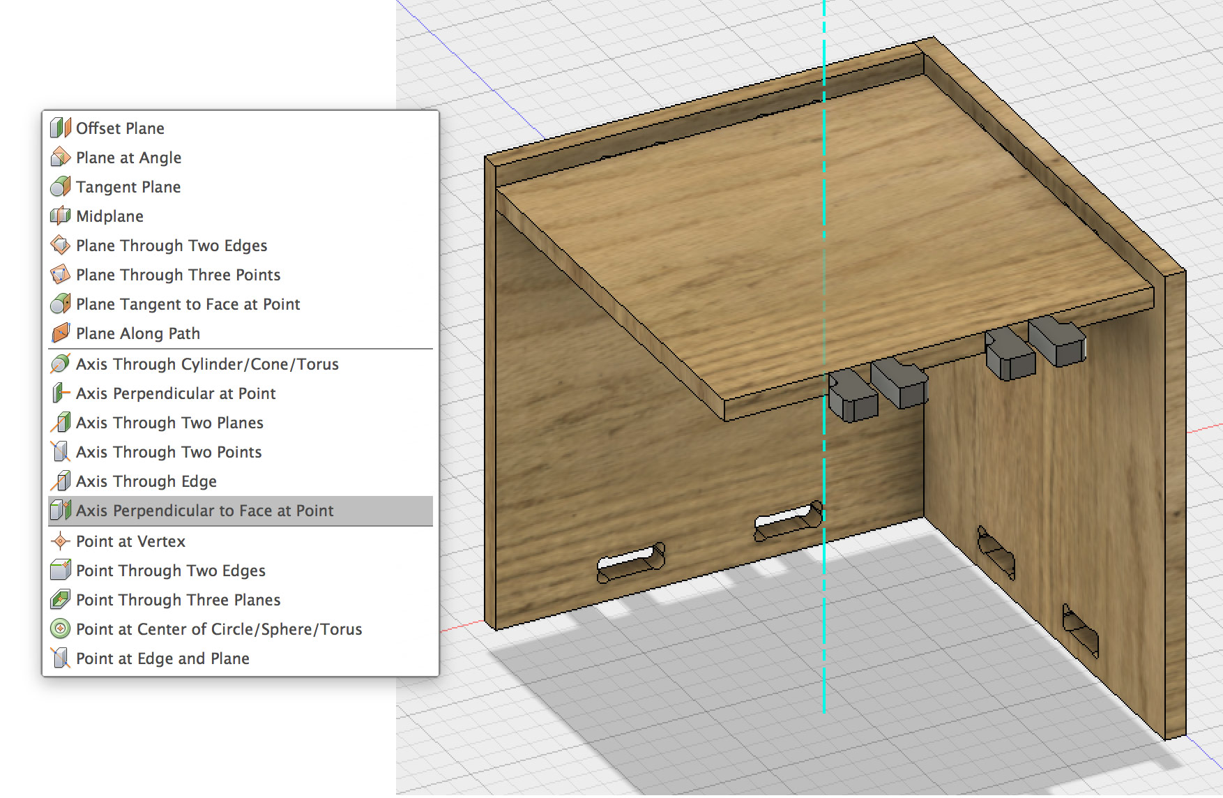
To create the axis, create a mid-construction line in a sketch (use the top face of the top part of the box as the base plane for the sketch), add a point in the middle of it. Then, outside the sketch, select Construct → Axis Perpendicular to Face at Point. There are two clicks to be made: the first one to select the face and the second one to select the point. Select the top face of the top surface and the midpoint you created before.
The same approach can be used to design the negative parts of the tabs. For the above mentioned mirroring and pattern tools one has to select the Features option for making the selections.
I left the final part mirroring as the last step. I created Left, Top and Front sides of the box first. Then I used the Create → Mirror tool to create the opposites: Right, Bottom and Back.
Toolpaths with Fusion 360 CAM
I chose to use Fusion 360 CAM as I want to continue to use my own computer for everything I create during the course. I also want to be able to use equipment and workflows at other labs and Fab Lab BCN is the first one that uses Rhino CAM for generating toolpaths for CNC milling. I do not plan to purchase a Rhino CAM license in the near future.
Before we continue with the toolpath generation, it is a good idea to create a representation of our stock. For the assignment I am going to use a sheet of 9mm thick plywood. The dimensions of the sheet are 2500x1250mm.
Convert all the bodies into components. Ground the stock by selecting it in the layers panel, right-click and select Ground Align the parts of the box to the stock material by using the Assemble → Joints tool.
- Select the face of a part.
- Select the top face of the stock.
- As the Type of the joint, select Planar.
- Flip it.
- Hide it by clicking on the bulb in the layer panel.
- Repeat the steps for each part.
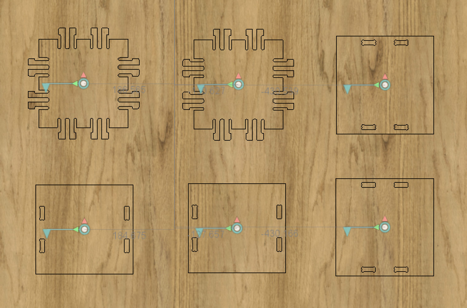
Once all the parts are aligned to the stock, you can unhide them one by one and move them around to find the best position on the material. Even though the stock object is grounded, the cursor of the mouse will try to highlight all the time. My solution to this was to hide the stock object and unhide the sketch that I used to create it. An alternative (and probably easier way) is to select the stock object in the layer panel, right-click and select the Selectable/Unselectable option. Below you can see how the layout looks like before we switch to the CAM mode.
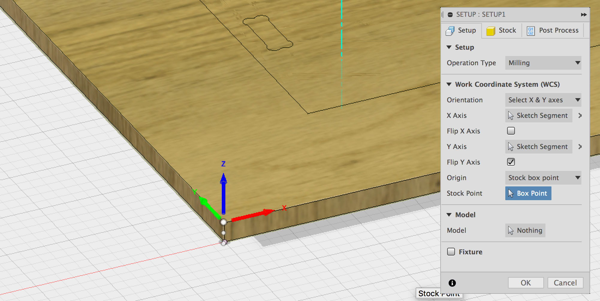
Once your design is ready, you have to go to the CAM workspace in Fusion 360. Create a new Setup by choosing Setup → New Setup.
- For Orientation choose Select X & Y axes.
- Click on X axis and select the longest edge of the stock.
- Click on Y axis button and select the shortest.
- Use the checkboxes to flip the axes if needed.
- For the Stock Point select the left-bottom-upper part of your stock object.
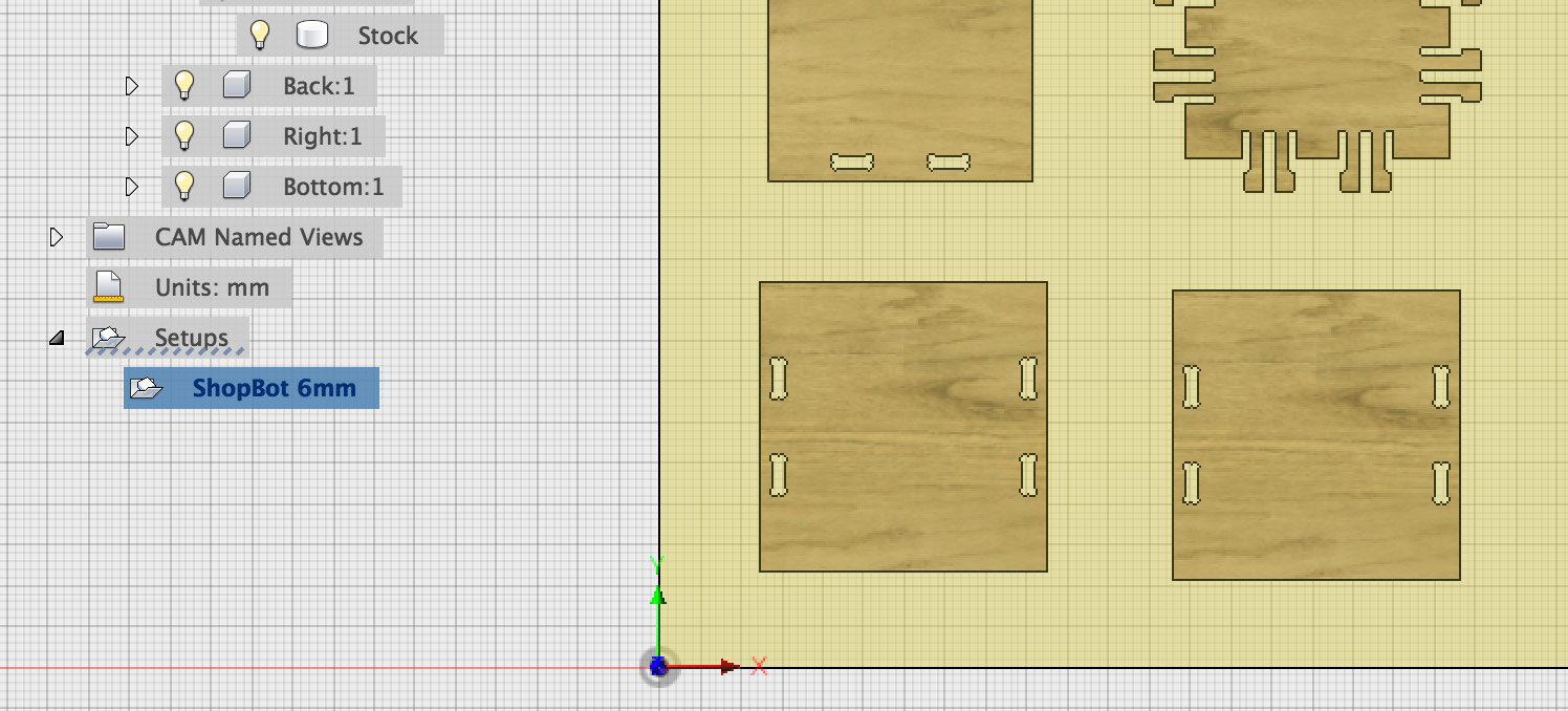
You should arrive to a state as in the following image.
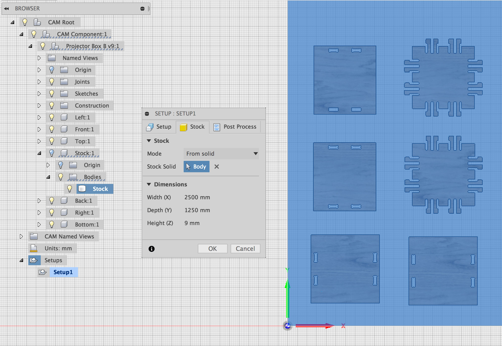
Continue the Setup procedure with the following steps.
- Click on Model and select the parts for cutting. This is going to be everything except the stock object.
- Select the Stock tab of the Setup dialog to set up the stock size.
- Set the Mode to From solid.
- Select the body of the Stock component.
- Click OK to confirm the setup.
- Rename the setup to match your machine and tool (ShopBot 6mm).
Below are some images that illustrate the steps above.
Creating a New Tool in Fusion 360
Before we can cut, we have to set up a tool that we are going to use for cutting. You can access the Tool Library from the MANAGE menu.
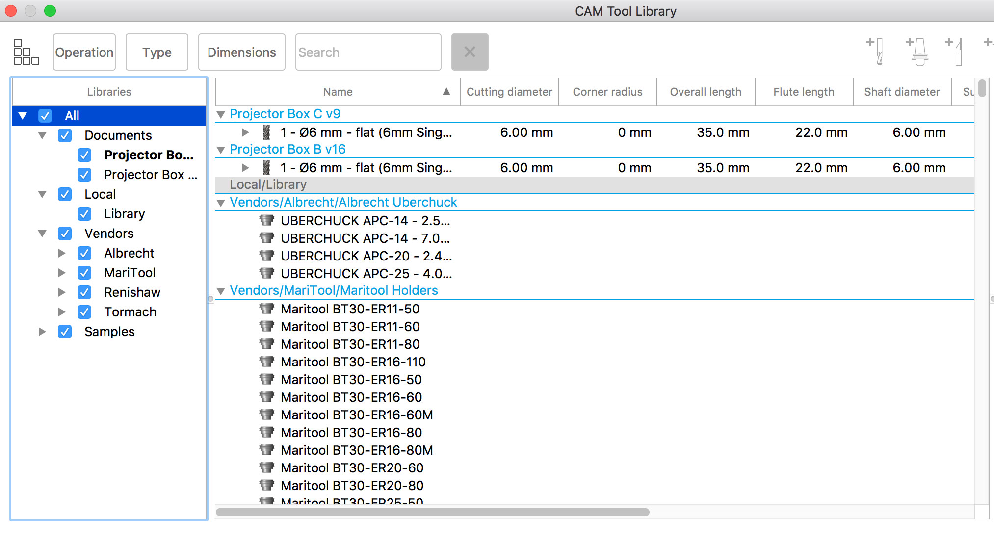
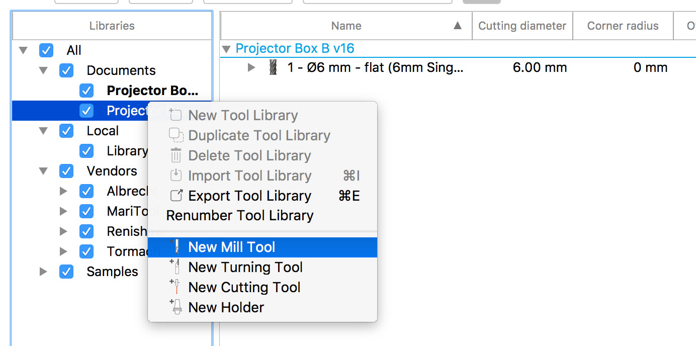
You can setup a tool on a per-project basis. Go to the Documents category in the Libraries menu to the left and select the item with the name of your project. Right-click and select New Mill Tool.
In the General tab set the Description to something that describes the tool, in our case 6mm Single Flute Flat End Fab Lab BCN, which makes it clear that we use a 6mm diameter tool which is flat-ended and it can be found at the Fab Lab Barcelona.
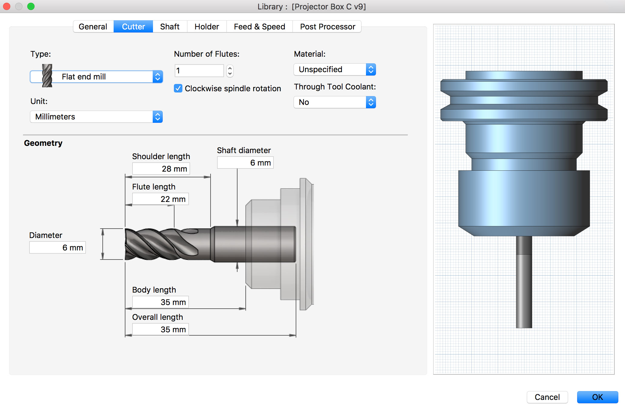
In the Cutter tab comes the essence of the tool definition. Set the following parameters in the header.
- Type to Flat end mill,
- Number of Flutes to 1,
- Check the Clockwise spindle rotation checkbox,
- set the Material to Unspecified and the
- Unit to Millimeters.
For the Geometry part of the spindle itself, use the following.
- Diameter: 6mm.
- Flute length: 22mm.
- Shoulder length: 28mm.
- Shaft diameter: 6mm.
- Body and overall length: 35mm.
In the Feed & Speed tab, set the Spindle speed to 12000rpm even though we will set the speed manually for the machine later. Calculate the feedrate by using the following equation FeedRate = N x CPT x RPM (look below for explanation of the params). Refer to Calculating Feeds and Speeds article from CNC Router Shop for more details.
FeedRate = N x CPT x RPM
N - number of cutting edges (flutes)
CPT - chip load (chip per tooth) is the amount of material, which should be removed by each tooth of the cutter as it rotates and advances into the work. (mm per tooth)
RPM - the speed at which the cutter revolves in the spindle. (Revolutions per minute)
Find out the chip load. Refer to the Typical Chip Load Values for Various Size Cutters table BELOW. In my case it is 1fl * 0.25mm * 12000 which equals 3000mm/min. So far I have seen the usage of 3200mm/min, but I will go with a bit less, since the quality of the cuts I saw were not satisfactory for me.
Typical Chip Load Values for Various Size Cutters
| Tool Diameter | Hard Woods | Softwood / Plywood | MDF / Particle Board | Soft Plastics | Hard Plastics | Aluminium |
|---|---|---|---|---|---|---|
| 3mm | 0.08 - 0.13 | 0.1 - 0.15 | 0.1 - 0.18 | 0.1 - 0.15 | 0.15 - 0.2 | 0.05 - 0.1 |
| 6mm | 0.23 - 0.28 | 0.28 - 0.33 | 0.33 - 0.41 | 0.2 - 0.3 | 0.25 - 0.3 | 0.08 - 0.15 |
| 10mm | 0.38 - 0.46 | 0.43 - 0.51 | 0.51 - 0.58 | 0.2 - 0.3 | 0.25 - 0.3 | 0.1 - 0.2 |
| 12mm and over | 0.48 - 0.53 | 0.53 - 0.58 | 0.64 0.69 | 0.25 - 0.36 | 0.3 - 0.41 | 0.2 - 0.25 |
In the Post Processor tab check the Manual tool change checkbox. Hit OK to confirm your new tool.
Marking Drill Points
On larger CNC milling machines one has to make sure that that the material is fitting well to the base surface of the machine. In order to do that on the ShopBot, one has to use screws. In order for us not to break the tool of the milling machine, we have to know where these skrews are. In order for us to know, we have to specify the locations in our design.
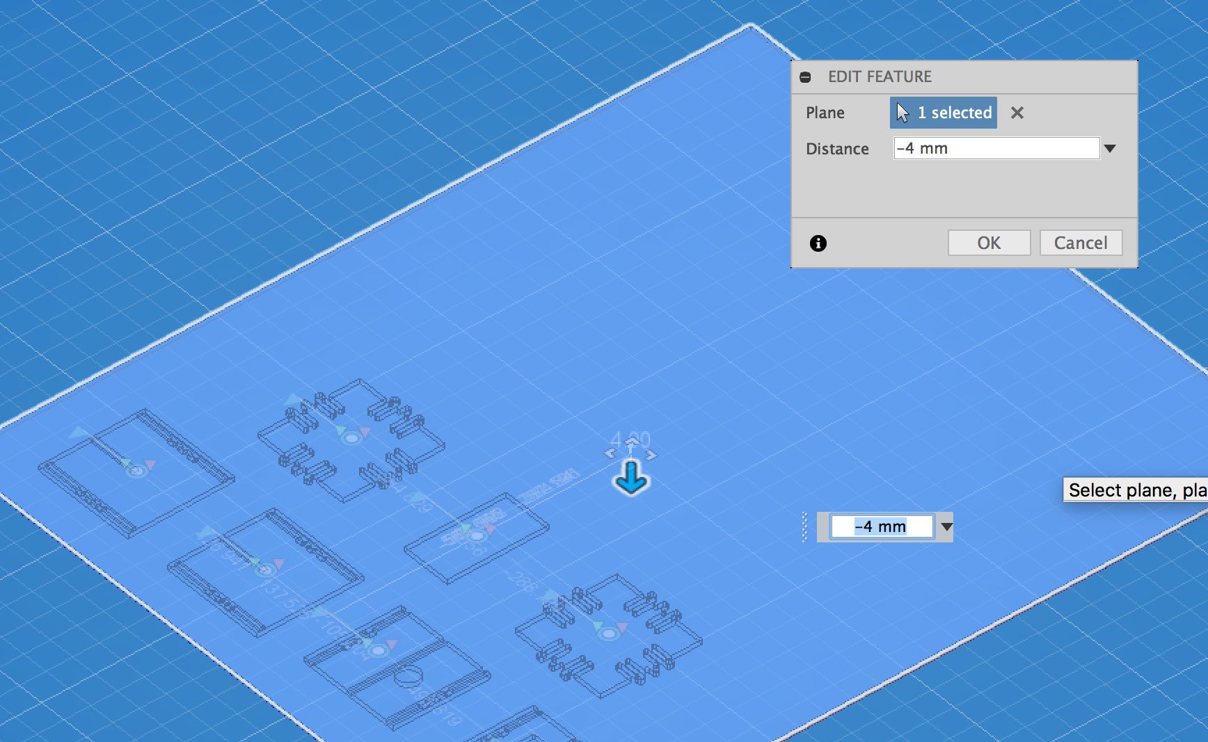
The way to do it in Fusion 360 is to create a sketch with points below the top surface of the material. Switch back to the MODEL mode of Fusion 360 and CONSTRUCT → Offset Plane. Select the top face of the material object and specify offset. In my case it was -4mm.
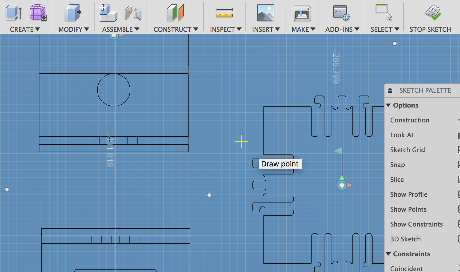
Next, create a sketch on the offset plane we just created. Make sure the milling layout is visible and add points in the sketch mode.
Go back to CAM mode and create a new 2D milling operation for drilling. There are two ways to do it: by clicking on the icon; right-clicking on the setup layer and choosing New Operation → Drilling → Drill.
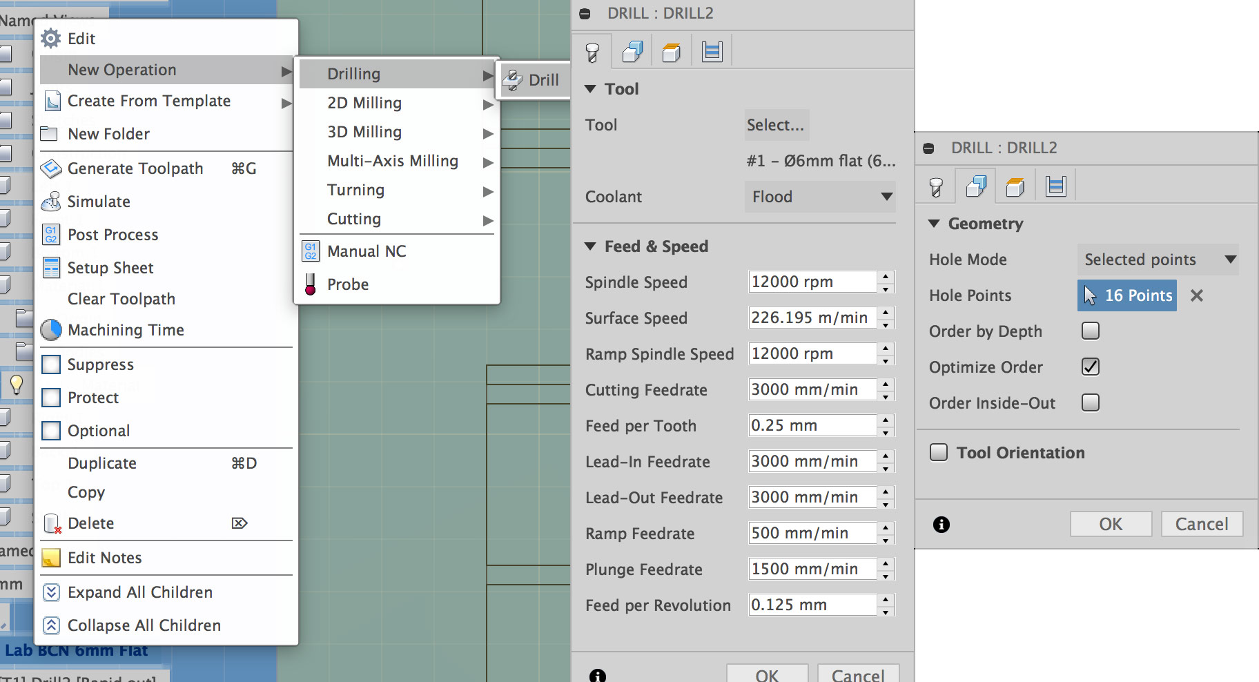
Go to the Geometry tab and set the Hole Mode to Selected points. Select the points from the sketch created few steps before. Select the milling tool that we created earlier and hit OK to confirm the drilling operation.
2D Pocket Operation
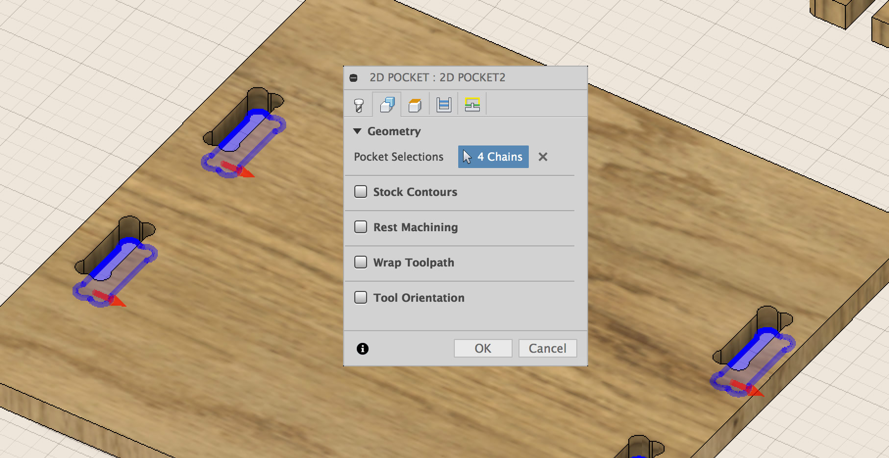
Click 2D → 2D Pocket to create a 2D pocket milling operation/strategy. For all the holes in my design I am going to create a 2D Pocket operation. Go to the Geometry tab of the 2D Pocket dialog and select pockets from your design that you want to cut. Make sure you select the right side (inside or outside) of the shape you want to cut by clicking on the red arrow.
In the Passes tab set the Sideways Compensation to Right (conventional milling). Set the Maximum Stepover to a value that is less than the diameter of your tool. In my case I will go with 5mm which is 1mm less than my tool diameter. In the Stock to Leave one has to define a negative offset that will be used to make sure that the tool comletely cuts the material. I found out that the leveling of the ShopBot here is not the most accurate so I went with -1mm.
Check the Multiple Depths checkbox. Set the Maximum Roughing Stepdown to be less than the tool diameter (5mm in my case). Set the Finishing Stepdown to the same value (5mm). Go to the Linking tab. Go to Ramp. Select Plunge for the Ramp Type.
Hit OK and at this point you should see your pocketing toolpath and be able to simulate it.
2D Contour Operation
Click on the 2D icon to select the 2D Contour operation. The last used tool is going to be selected by default. When selecting the contours you want to cut in the Geometry tab, make sure that you set the right direction for the tool to move.
The red arrow should point in the clockwise → direction.
In the Geometry tab you should add Tabs. Select the Tab Positioning to be At points. For the size of the tabs 4mm is good for the Tab Height and 6mm for the Tab Width. Select points where you want your tabs to be. In the Passes tab check once more if Right (conventional milling) is selected. Define Stock to Leave in the Passes tab to be 1mm.
For the Multiple Depths part in the Passes tab, set the Maximum Roughting Stepdown and Finishing Stepdown to be less than the diameter of the tool, 5mm in my case.
Finalizing Toolpaths
Simulation: it is a good idea to make use of the simulation option to check for potentioal fails. Select the Stock option to see the material being removed during the toolpath playback process.
Post Process: go to Actions → Post Process to create machine code for your milling machine of choice. Under the Post processor dropdown select the ShopBot ISO post processor. Under Properties leaving the defaults is fine.
Save the file and consider ways of transfering the file to the computer connected to the ShopBot machine.
Machining
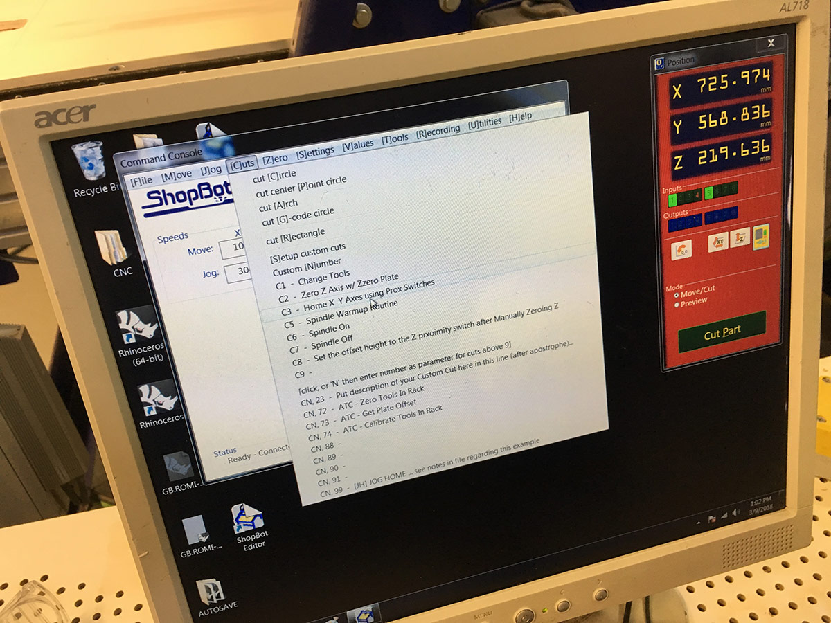
ShopBot milling software is being used at Fab Lab Barcelona. There is a stationary PC computer connected to the machine. ShopBot Command Console is used to drive the machine.
After turning the machine on (you usually have to get the key and then turn a red knob on the main controller box of the machine) first thing to do is to set the home of the X and Y axes by using the proximity switches of the machine. The command for that is C3. Below is an image where you can find that in the menu.
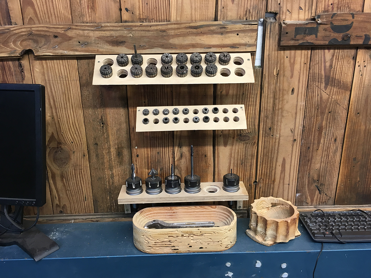
Once that is done, it is time to choose the tool. In my design I used the 6mm flat end single flute tool, this is what we have to choose from the collection that can be seen in the image below.
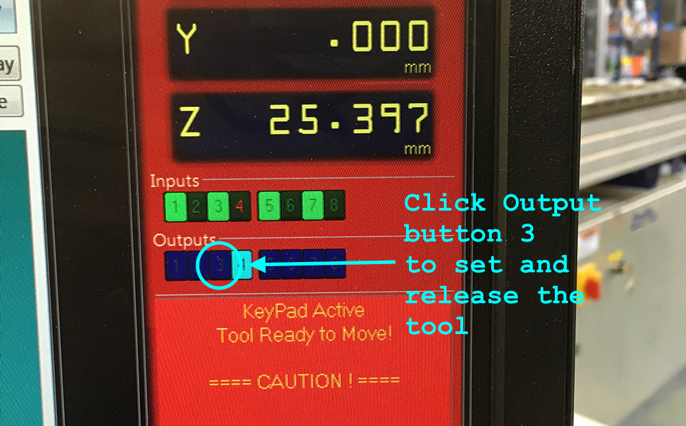
To fasten the tool in place, one has to use the ShopBot software Position panel. In the panel one has to click the Output button number 3 to open and close the vacuum vent that holds the tool in place. The following image and video shows which button to click and how does it look like on the tool side.
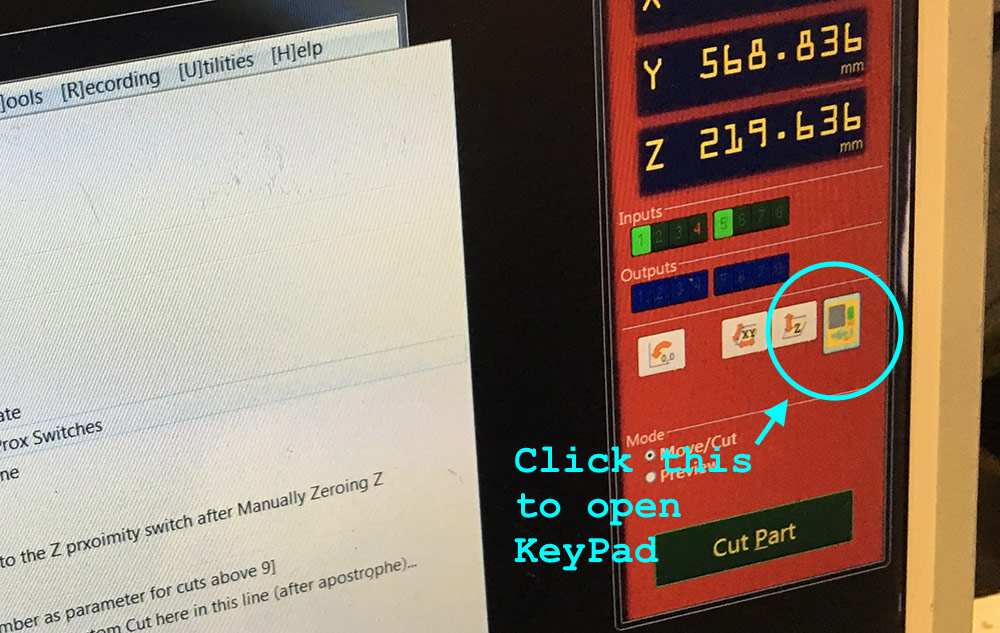
Next one has to set the origin for all axes. For X and Y axes one has to use the KeyPad of the ShopBot software that can be opened by clicking on the yellow pad icon in the Position panel. After positioning the tool above the origin on your material, click the Zero Axes button in the KeyPad panel and select X and Y (not Z) axes to zero.
To zero the Z axis we are going to use the Zero Plate which is a metal plate to put under the tool on top of the material. Use the C2 command to initiate the process and watch the following video to see how it goes in detail.
Then we have to make sure that the cooling system is on. On the spindle mechanism there is a vent to be opened. Below is a video where Santi explains where and how to open and close the vent.
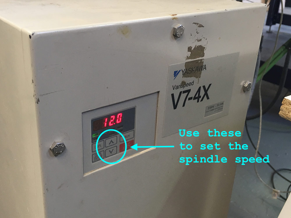
The spindle speed has to be set manually for the Fab Lab Barcelona ShopBot. For that there is a box YASKAVA Varispeed V7-4X with a push-button interface that can be used to set the spindle speed.
At this point FINALLY we are ready to launch our first milling job. The first one on this ShopBot machine is always to mark the places for the mounting screws. The material has to be kept in place and on the Fab Lab Barcelona ShopBot it has to be done using wood screws. So that the milling tool does not hit the screws during the milling process, we need to integrate the screw points in our design.
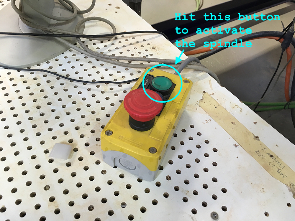
To load the first strategy, use the menu option FP (File / Part File Load). ShopBot software will open a dialog where you can choose your strategy file (usually with an extenstion .sbp). Then it will ask you to activate the spindle. Hit the green button on the box visible in the image below to do so, then hit Enter on the keyboard to start the job.
This is how it should look like in action.
Use available wood screws to fasten the material to the sacrifying layer of the machine. Once that is done, use the Zero Plate to re-zero the Z axis again.
Remember to zero the Z axis again after attaching the material to the sacrifying layer.
At this point feel free to load and run the rest of the strategies that you have prepared. Use the FP (File / Part File Load) option to load and run them. Below you can see a video of me milling the first version of the projection box.
You can use this rotational tool to remove the tabs after milling.
Add some sanding.
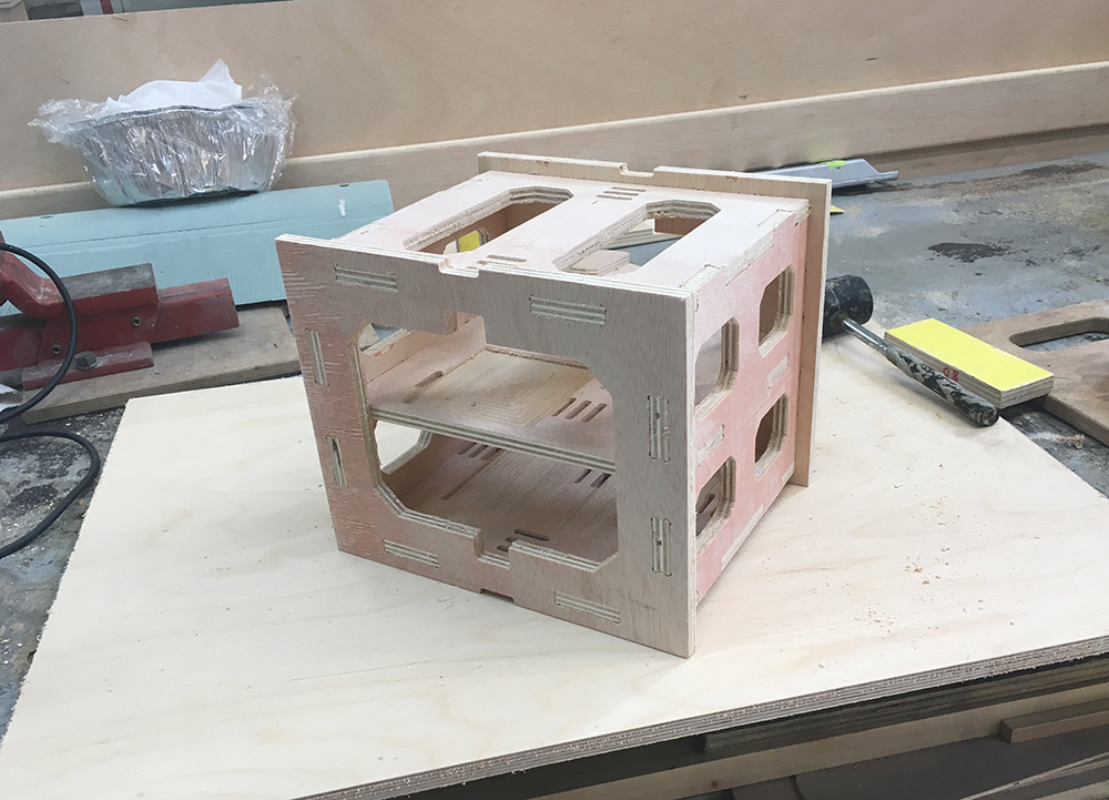
I did make multiple versions of the projector box. The first version (Fusion 360 design described above) did not work out too well. Below you can see an image of how did it look like.
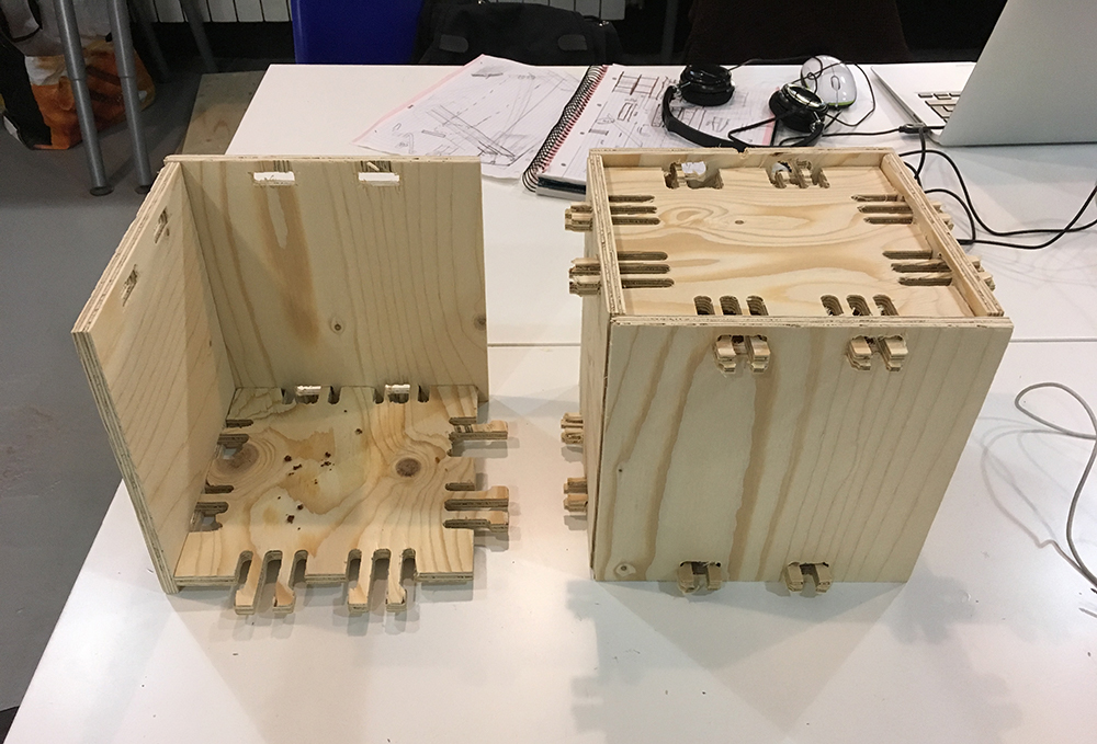
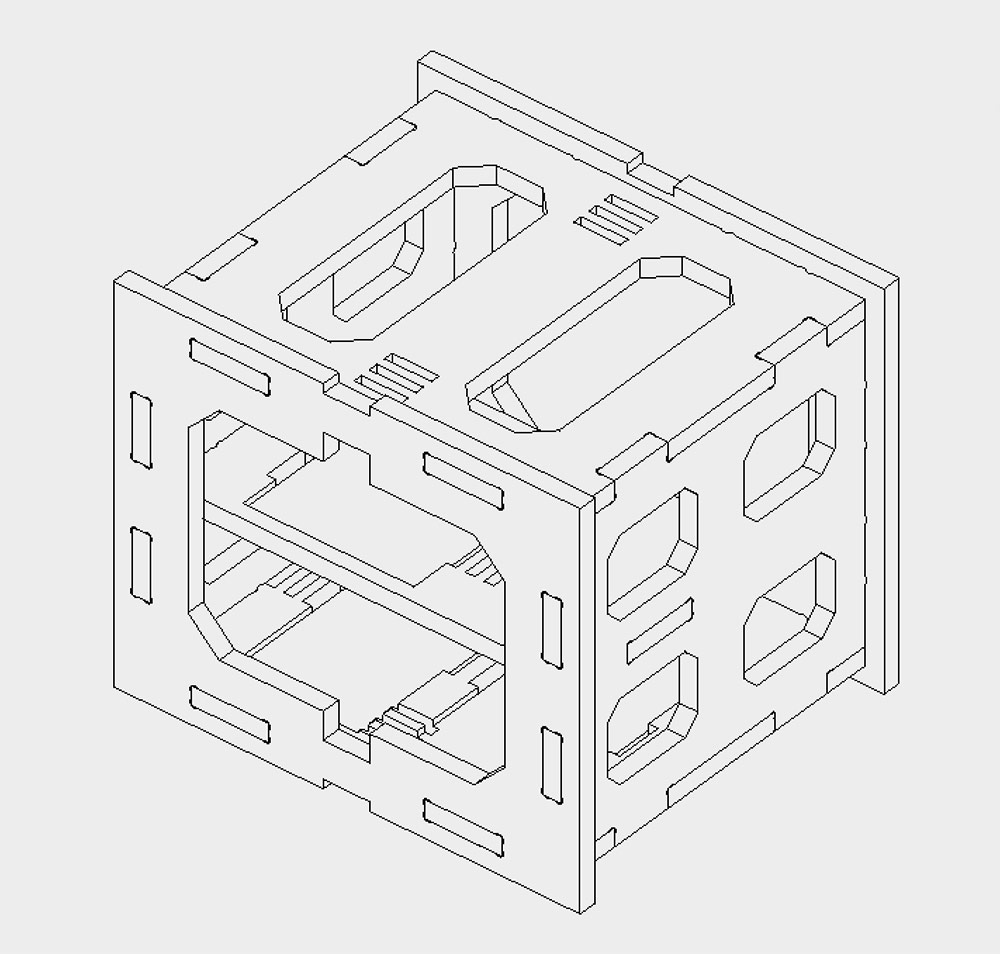
I was not sattisfied with the many iterations required to make the spring joints to work and I wanted a better material for the boxes anyway. Thus I made a new version of the box incorporating regular finger joints using Fusion 360. You can see an image of the design below.
For this version I used 12mm plywood that was better quality and lighter. I broke a tool while milling six copies of it to be later used in a projection mapping workshop. Below a video from the milling process of the version 2.
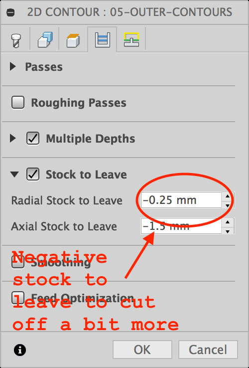
I had to do a few tests to get the kerf right. I ended up with 0.25mm kerf that in Fusion 360 can be set while generating the strategies. You can use the Radial Stock to Leave parameter to control how much extra material the machine has to cut (in the case of a negative stock to leave which was my case). Below is an image with the menu.
And the final result I was happy with.
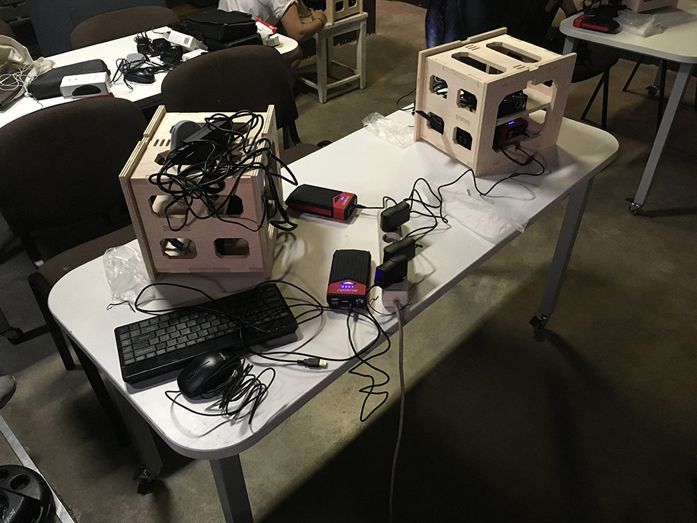
I used six of these for a workshop called Radical Projection Mapping Lab in Liepaja, Latvia. It was a three-day workshop where participants learned to use open source software for projection mapping with the Raspberry Pi. The boxes housed projectors, Raspberry Pi’s, batteries and game controllers to enable participants to go and map outdoors. Below an image from the workshop.
Evenings during the workshop were reserved for outdoor trips where we would experiment with the possibilities of the solution. Below is an example video of how it looked like.
Conclusions
CNC is one of the most interesting and also the most demanding parts of the course. There are a lot of details to be taken into account. One week is not enough to understand the depths of it. I felt lucky because I had previous experience with it.
Before the week I was dreaming of being able to generate toolpaths with Fusion 360. Now I can use Fusion 360 to generate toolpaths for any machine if I would like to. Being able to define a new tool in Fusion 360 gives me the power to not rely on any of the default tools preset in software. I can go to any lab, understand the specifics of the machine there and create strategies with Fusion 360 without learing a new software tool.
Being able to gather courage to edit plain GCode was a great thing to experience as well. There were things that Fusion 360 did not calculate correctly for some reason. I had to update the X and Y feed rate manually (by using the find and replace function in a text editor).
Being able to generate complex strategies with tools like RhinoCAM and Fusion360 gives a lot of power. Being able to tweak the GCode after gives the missing pinch of precision and efficiency that sometimes can be useful for getting things done in time. Without editing the raw GCode in my case would result in 4x slower cutting, thus I would not be able to finish the projection boxes before leaving to run my workshop.
All in all I feel like I put more energy into this week as I should have done, but the fact that the things I made were actually used for a project makes me feel completely sattisfied.