
Week 11
This week is for exploring sensors and enhancing our boards to be able to process sensor input and preferably to send it to a computer for further processing.
My final project has a 2-axis push-button on board, thus for this week I would like to explore something related to that. Luckily, before being able to get my hands on the task, my 5-Way Tactile Switch breakout board from SparkFun arrived.
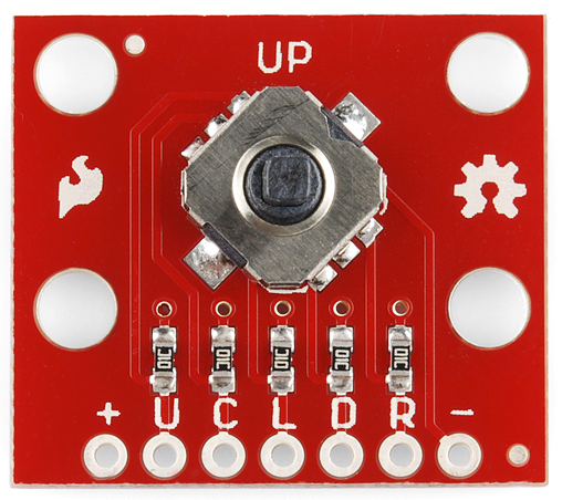
5-Way Tactile Switch has 5 buttons: top, right, bottom, left and center. Thus it has a separate digital pin for each of these switch directions. Therefore ATTiny44 that I already used in my Hello Board is the perfect candidate for sensing all of those pins.
What I want to do is the following.
- Integrate the 5-Way Tactile switch into my Hello Board design.
- Program it to send data on which button is pressed via serial connection.
- Adjust my mapping software code to react to the buttons in a reasonable way.
Let’s start with designing the circuit.
Designing the Circuit
I decided to start with the existing Hello Board design that I did in Eagle. After the Electronics Design week it still worked during the Embedded Programming week, thus I thought it is a good idea to build on top of it.
I had to decide whether to integrate a connector to the breakout board (since I did not get the switches separately yet) or look ahead and make a board that is already compatible with the switch alone. I decided to go with the latter.
I disconnected the push-button and was left with 5 free digital pins of the ATTiny. I need exactly 5 to be able to sense the 5-axis switch.
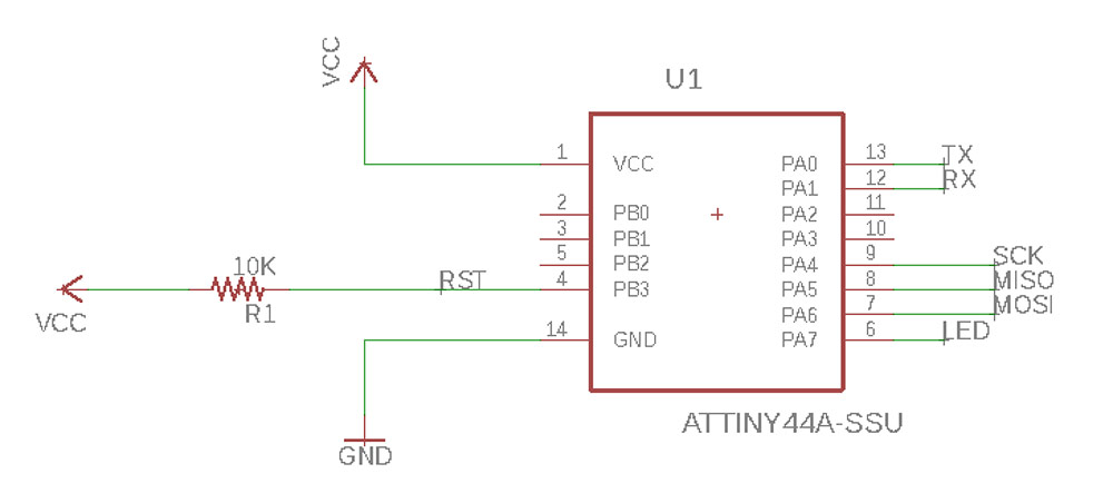
Here you can see that the free ones are PB0, PB1, PB2 and PA2, PA3. The rest of the pins are connected to the ISP programmer header, FTDI connector for serial communication and a LED. I decided to leave the LED there to be able to tell if the board is on or not.
Next challenge was to find the Eagle part library that would feature the switch. Luckily there is SparkFun Eagle library on GitHub and the SparkFun-Switches part of it has the COM-10063 in it.
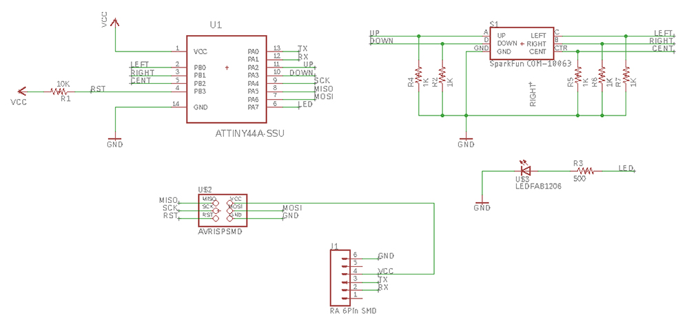
Each of the directional buttons have to be connected to the IC in the same way as a regular button. In the initial Hello Board design I used a pull-up resistor, which would provide a HIGH state to my button if it is not pressed and a LOW state when pressed. This time I would like the button pins to be pulled LOW, thus I will use pull-down resistors for each of the direction buttons.
Below is a formula (from electronics-tutorials.ws) to calculate the resistance of the pull-down resistor we want to use. One has to take into account the voltage that the MCU considers to be LOW. I will take the TTL logic gate as a reference, which states that the maximum voltage for a voltage to be considered LOW is 0.8V.

I also do not want to stay exactly on the edge, thus I want a voltage that is between 0V and 0.8V. If I go with 0.4V, the resistance I get is 1kΩ.
One problem that I had while drawing the board was that I kept getting ERC warnings about the RTS and CTS pins coming from the FTDI connector that were not connected anywhere. The way I solved it was to remove the labels and thus the connections from the FTDI header symbol in the schematic.
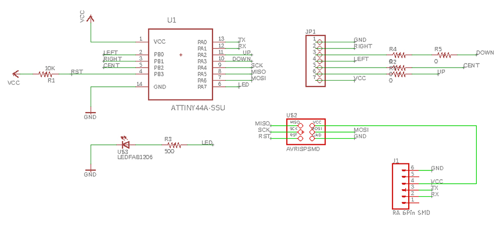
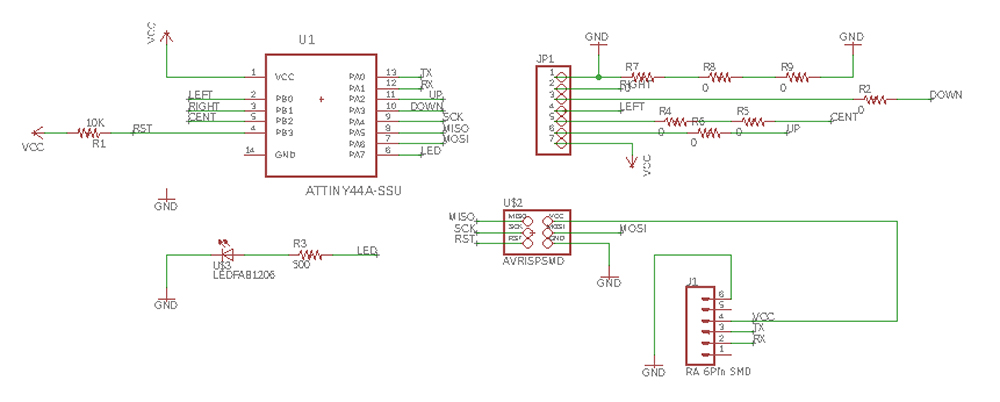
Below is an image of the schematic I made.
Next is to lay out the parts on my PCB! I had to add 8 0ohm resistors to wire everything. Below you can see the wiring of the PCB at this state.
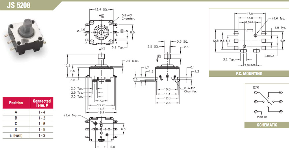
At this point I looked at the breakout board of the switch and thought: why don’t I use it as it is? Another reason to do so was that I ordered a different kind of tactile switch from DigiKey. The E-Switch JS5208 navigation switch is similar to the SparkFun COM-10063, is not twisted 45deg and at this point seems more available than the SparkFun one. In the long term I believe I have to make two different designs to house both of them. Price comparison shows that the SparkFun switch is 1.60e per unit and the one from E-Switch is 2.44e per unit.
To make use of the SparkFun COM-10063 breakout boards (without desoldering the switches) I decided to create a connector for the breakout board of the switch.
There are 7 pins to be connected and that could be done with a 7-pin female header. Where to find it in Eagle?
There is a pinhead library in Eagle, but it contains only male headers. While looking for answers on Google, I ran into the following comment by michaelwylie on Element14 forums.
I don’t use Eagle, but unless you are 3d modeling wouldn’t the header footprint be the same for both male and female headers?
Which is true. I went on to try that and was lucky enough to find a 7-pin header in less than a minute. Next, all I had to do was to label the pins! I ended up with the following schematic.
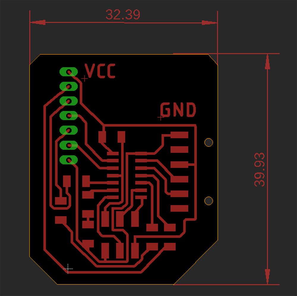
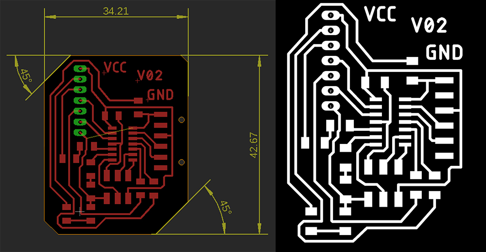
Then I went on to create the PCB layout and learned a few new things on the way: how to create a custom outline; and how to add dimensions to the design. Below you can see how far I got.
Then I exported the Top, Pads and Dimension layers to a monochrome .png image with 500dpi resolution. After I used Photoshop to create .png images that I could use for toolpath generation in Mods. I am adding a tutorial on how to create .png’s for traces, holes and contours in the Computer-Aided Design week documentation.
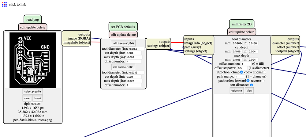
For some reason the updated version of Mods did not want to mill the detailed parts (for example the three traces under the ATTiny44 chip). Below you can see the Mods settings I used.
And the following image shows what was the result after milling traces, holes and contours. You might ask: what was the problem with the small one? The problem was that when you use the File → Export As menu, images are exported as 72dpi. Photoshop resizes the pixel array as well. The resulting image is smaller and I changed the resolution setting to 500dpi in Mods before generating the milling code.
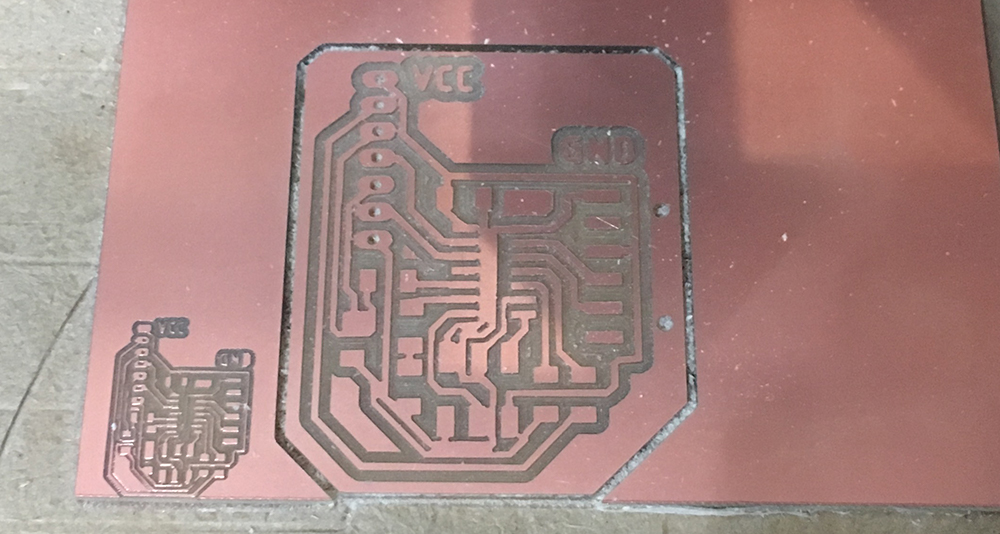
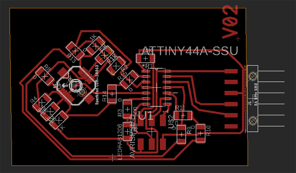
As you can see, it did not really mill through. I double-checked settings in Mods and tried different versions of .png files and editing approaches, but no success. I went on to create the 02 version of the board.
I set the clearance value in Eagle to 20mil instead of 16mil.
And redesigned the board to match the changes. I added a lot of 0ohm resistors, probably they could be avoided if I would not stress myself so much about the ISP connections.
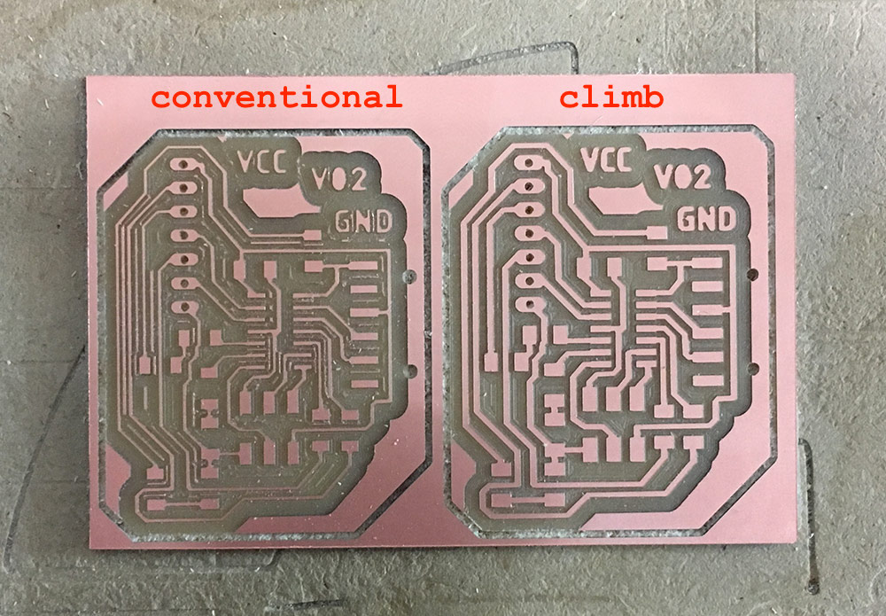
My intuition was correct and the new version of Mods did generate toolpaths to cut everything nicely. I did an experiment where I set the milling direction to conventional instead of climb as in the mill traces (1⁄64) preset. You can see the difference in the result below.
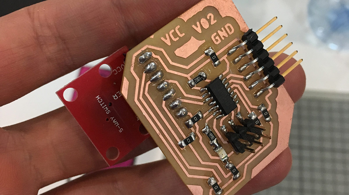
As the following thing I soldered the female header for the 5-way switch to test if it fits. It did, so I moved forward and soldered the rest of the parts.
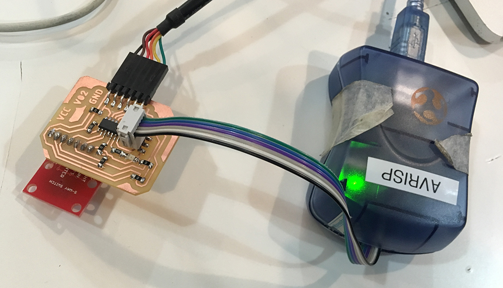
Soldering of the rest of the parts went without problems. I connected the board via AVRISP MK2 and used Arduino IDE to burn the bootloader. I chose the internal 8MHz resonator as the clock setting.
After testing if all of the 5-way switch buttons work and are able to trigger a LED, I went on to figure out, how to detect and sent the down state of a button. I started with the left one.
void loop() {
  bool left = !digitalRead(LEFT);

  if(left){
    digitalWrite(LED, HIGH);
    if(!b_left){
      Serial.write("LEFT");
      b_left = true;
    }
  }else{
    digitalWrite(LED, LOW);
    b_left = false;
  }
}
This worked without problems. And the next step was to figure out how to detect and send the up state. The important part here is that I want to send the messages only once: when a button is pressed, a PRESSED message is sent; when the button is released, a single RELEASED message is sent. I improved the if statement with another recursive if.
if(left){
  digitalWrite(LED, HIGH);
  if(!b_left){
    Serial.write("LEFT PRESSED");
    b_left = true;
  }
}else{
  digitalWrite(LED, LOW);
  if(b_left){ // I added this one here
    Serial.write("LEFT RELEASED");
    b_left = false;
  }
}
It worked perfectly and I got the following output in the serial console while pressing and releasing the left button.
LEFT PRESSEDLEFT RELEASEDLEFT PRESSEDLEFT RELEASEDLEFT PRESSEDLEFT RELEASEDLEFT PRESSEDLEFT RELEASED...
Next, I wanted to do this for all the buttons. The fast and easy way was to copy, paste and replace the left button variables with the rest of the buttons. With that done, the compiler started to complain as the chip run out of memory.
Global variables use 267 bytes (104%) of dynamic memory, leaving -11 bytes for local variables. Maximum is 256 bytes.
First guess was to reduce the amount of data being sent over serial connection. I still wanted to keep working with Arduino libraries, since I wanted to get the full cycle working as soon as possible. So I tried to optimize the code. For each button press I would send two characters: one that would define the direction and another one that would define the pressed or released state. I decided to use the already existing defines to identidy the buttons.
#define UP 2
#define DOWN 3
#define LEFT 10
#define RIGHT 9
#define CENTER 8
Then I added a function that would take the ID of the button and a boolean pressed state that would then be forwarded via serial connection.
int sendButtonState(int button, bool pressed){
  Serial.write(button);
  Serial.write(pressed);
}
It did not really work at first. But that was probably because of the Arduino serial console not being able to translate the bytes. So I went on to the next step and opened my projection mapping project.
It was possible to see the incomming bytes that describe the directions. They matched the ones that were defined in the Arduino code. Next problem was to figure out how to read the pressed and released byte. If I always read two bytes, how do I tell which is the first one.
It is time to add a separator. I will define it as the ASCII number 32 which stands for space.
#define SEPARATOR 32
I am going to send an additional separator byte after each 5-way switch event. I changed the sendButtonState function into the following.
int sendButtonState(int button, int pressed){
  Serial.write(button);
  Serial.write(pressed);
  Serial.write(SEPARATOR);
}
On the other end I used C++ application with the openFrameworks creative coding library, that has relatively simple access to serial devices. In each update loop I would add the serial bytes to a buffer and then check for chunks of data with separator at the end.
int numSerialBytes = serial.available();
if(numSerialBytes){
    for(auto i = 0; i < numSerialBytes; ++i){
        buffer.push_back(serial.readByte());
    }
    serial.flush();
}

if(buffer.size() > 2){
    for(auto i = 0; i < buffer.size(); ++i){

        // Check for separator byte
        if(buffer[i] == SEPARATOR){

            // There must be two more bytes before
            if(i > 1){
                int direction = buffer[i-2];
                int state = buffer[i-1];
                std::cout << inputToString(direction, state) << std::endl;

                // Delete interpreted bytes from the buffer
                // Separator byte, direction and state bytes
                buffer.erase(buffer.begin(), buffer.begin() + i + 1);
                i = 0;
            }else{

                // If there are less than two bytes before,
                // flush them.
                buffer.erase(buffer.begin(), buffer.begin() + i + 1);
                i = 0;
            }
        }
    }
}
This worked perfectly and the next step would be to connect this to my projection mapping application. The button mapping for this example was very simple. I would have a single surface on the screen and I would need to select corner points and move them around the screen.
CENTER → Select next corner
UP, DOWN, LEFT, RIGHT → Move corner
I also took advantage of timer. Five seconds after no action takes place, mapper enters presentation mode and saves composition.
The following video demonstrates how it works.
This is it. Mission of this week accomplished. Take a look at the full source code to get a better idea on what is going on.
Conclusions
Even though a button may seem a simple sensor, there are a lot of small details that are involved. First of all small decisions, such as should I connect it to the same pins as ISP programmer or better chose pins that are not used by that? Could I use less pins if I would use a muxer? Should I use a pull-up or pull-down resistor? What is the best value for that?
After testing the board I also realize that the resistors used on the 5-way switch breakout board are pull-up resistors, which feeds the input pins with HIGH when buttons are not used. During the next week, one of my tasks will be to use a plain SMD version of the switch and use a pull-down resistor for each button instead.
This week can be considered special as I started to see how things start to connect with my final project. Electronics are in the core of it and only when I have the first version of the circuitry, I can start thinking about the enclosure that could be made with 3D printing or in the most optimistic case–with injection molding by using recycled plastic.
Among the things that I learned are the following.
- How to work with dimensions in Eagle.
- How to use Photoshop to prepare PCB milling input files for Mods.
- How to use Mods for PCB drilling operations.
- How to use ATTiny44 with its internal 8MHz clock.