add an output device to a microcontroller board you've designed, and program it to do something
Following on my last week's idea of making a cat-trap, this week I am going to be working on the mechanical part of the device. In order to do so I will do Neil's Servo Board, which allows me to control motors that can make parts of the cat-trap move.
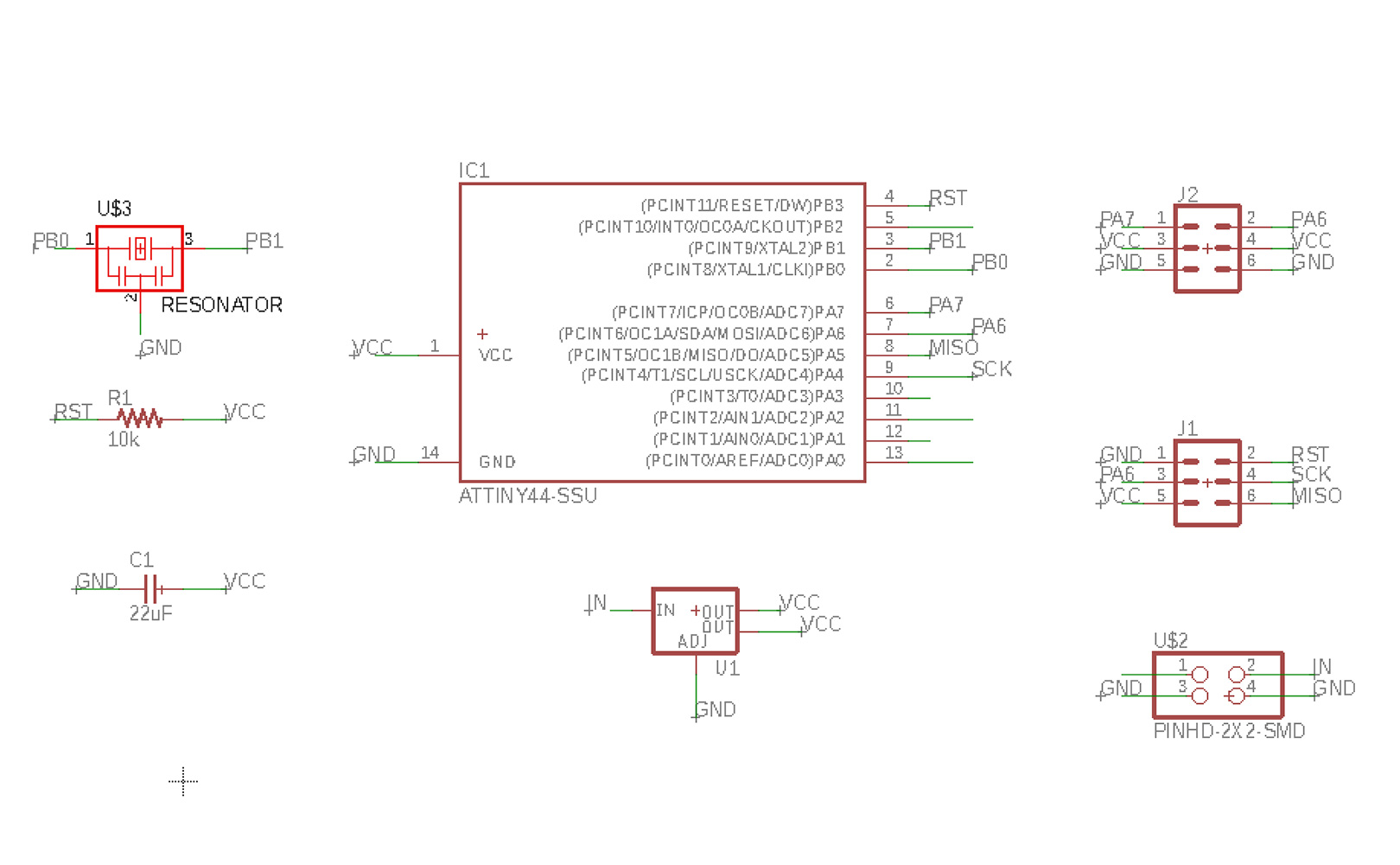
I used Neil's Servo Board which does this.
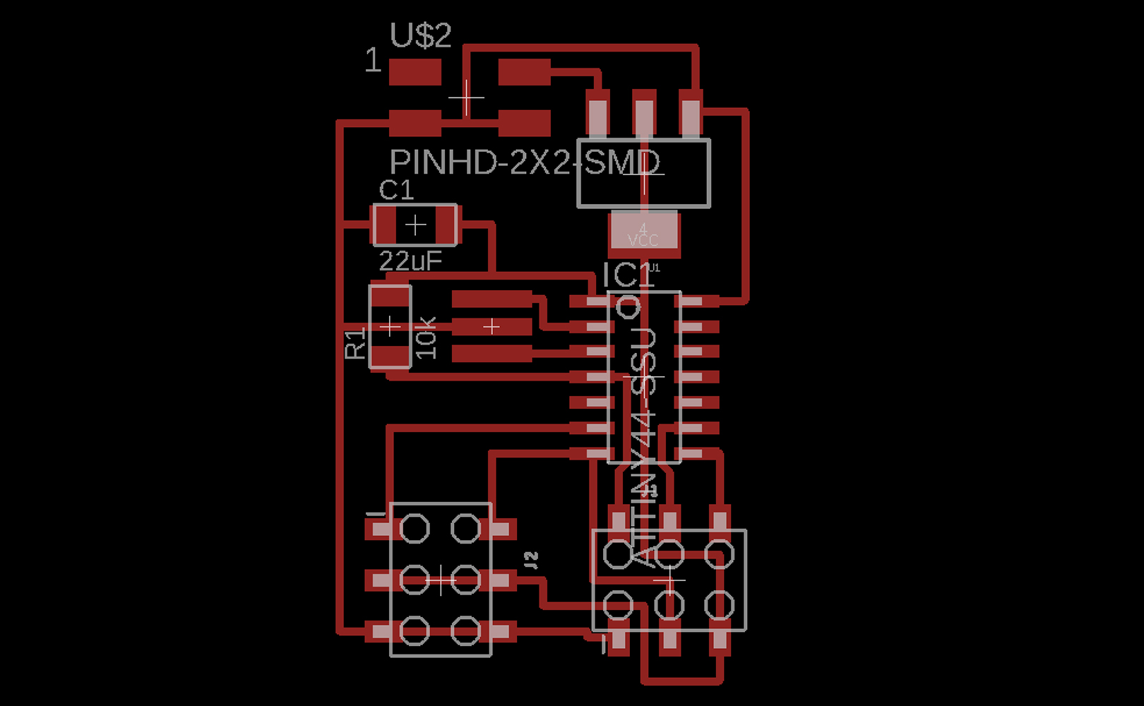
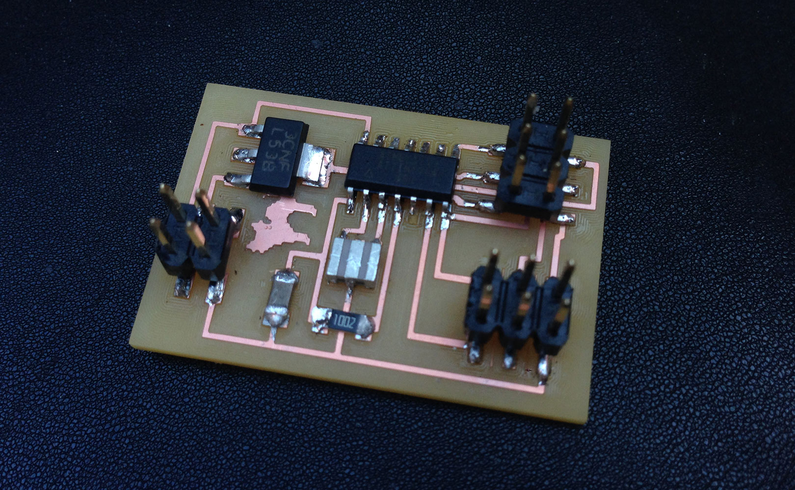
Luckily, I noticed that one of the components on Neil's board, the voltage capacitator, was different as the ones we have in the lab. This was crucial to find out before doing the board design in Eagle as the pin connections would not have worked. This is the datasheet for the voltage capacitators we have in the lab called SOT-223 where I could see how to properly connect the component in my board. This is the reason why my board looks different than Neil's motion borad, as I had to rotate the voltage capacitator to be able to make all the connections.
I used the following components in my motion board:
- Resitor 10k
- Capacitor 22uF
- ATTiny 44
- Crystal 20MHz (Resonator)
- Voltage regulator SV
- 2 Connectors 3x2 (Female)
- Connector 2x2 (Pinhead cut)
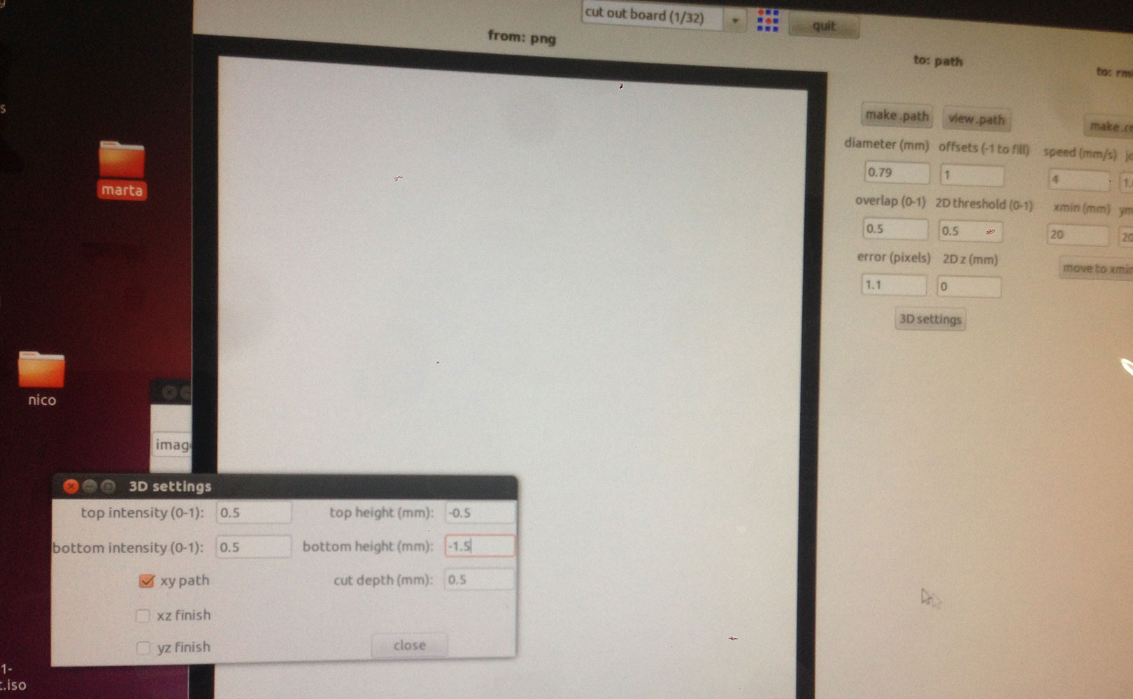
This time I used a new machine to mill the PCB, the SRM-20. It works exactly the same as the other milling machines, with the exception of having a slightly more manual process:
- There is no software to communicate with the machine, instead it is done through commands in the console. To start talking to the machine simply open the console and type "fabmodules", a window will pop up and simply follow the instructions and add the paremeters as always to generate the .rml file.
- Another difference is that this machine doesn't store the x,y,z values, so remember to always write down the coordinates numbers!
- Something else to keep in mind with this machine is that the job can't be easily cancelled in case something goes wrong, you have to wait for the machine to finalize milling the board.
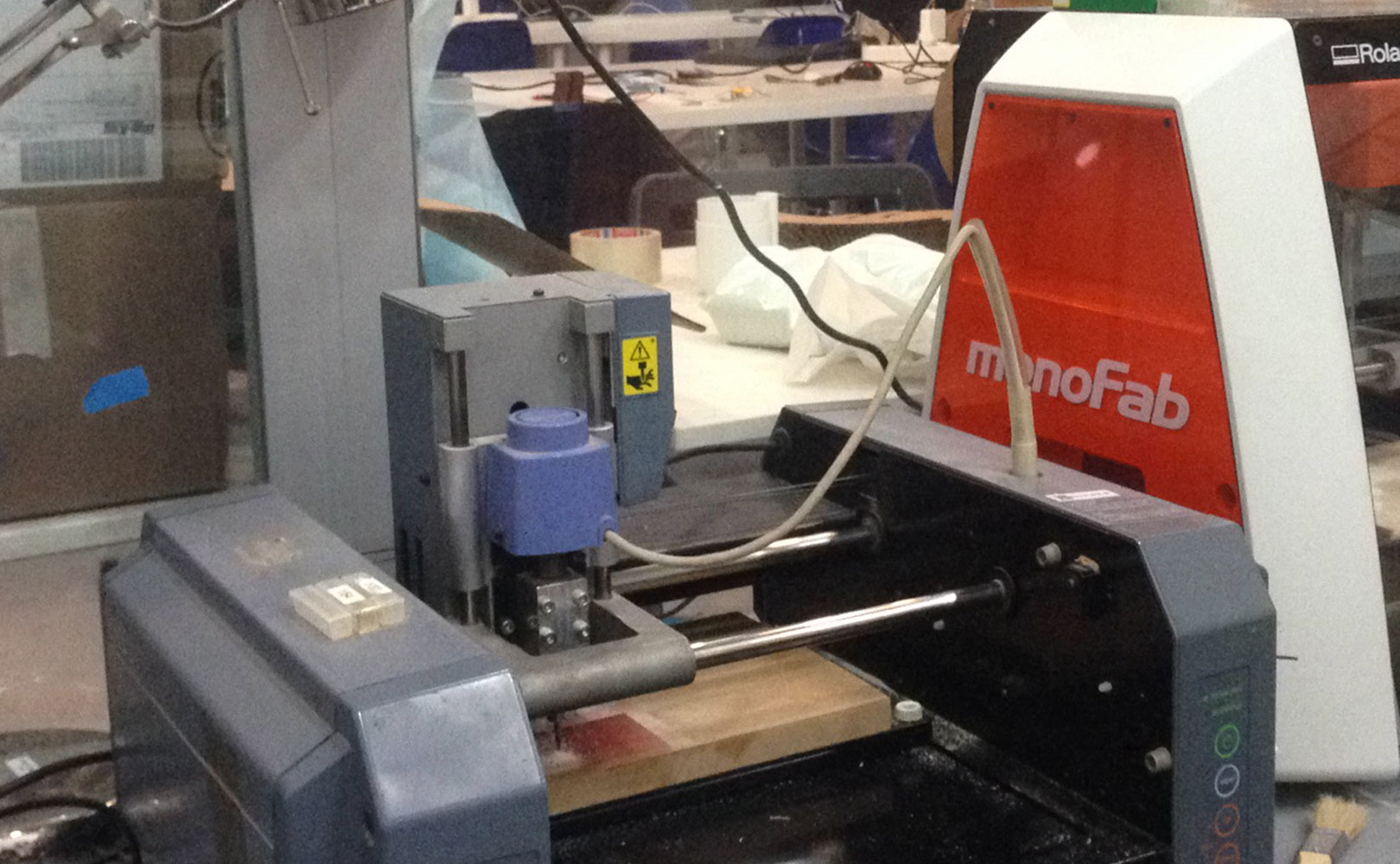
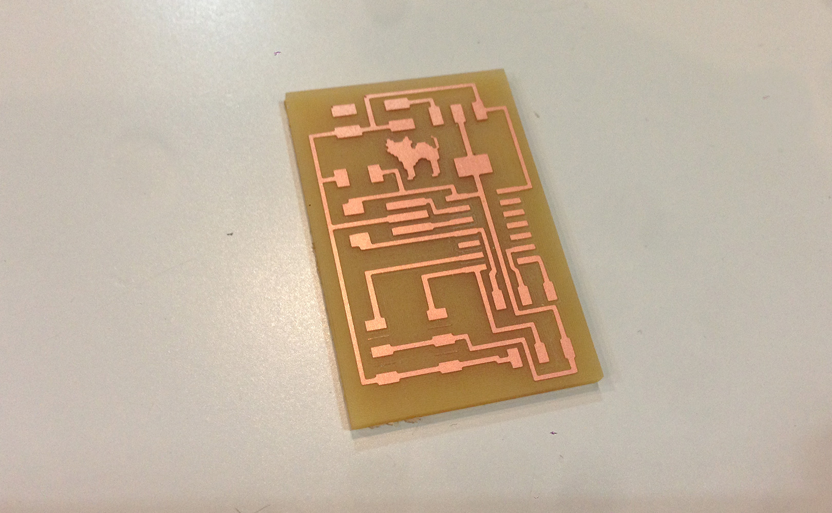
PCB board once milled. Overall I loved using this new milling machine.
See also below the board with all the components once solded.
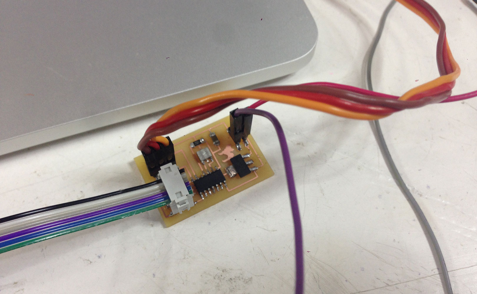
I programmed the my board with Arduino and connected the servo. I tested the board and checked everything was working properly, and it surprisingly did.
Once this was done I looked for instructions on how to connect and programm the servo in Arduino. Images below show the whole setup of how and what to connect where. In this case, the board is connected to a "??" because it needs a power supply to recieve the 5V from (it could also be a battery).
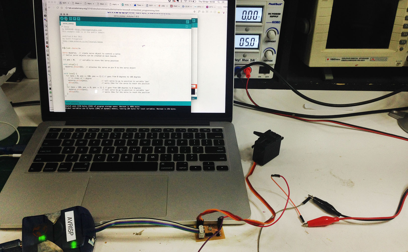
The process of building the board had been easy enough until now. I wanted to test the servo movement and power by sending the Arduino Sweep code, but eventhoug everything was correct, the servo would only move for one second and then stop. I was told by technitians and help from the FabLab that this is due to a conflict in the communication betweeen the AtTiny 44 and Ardunino, aparently this is very rare to happen but sometimes it does happen. This meant that I could not program my servo using Ardunio language, instead I used Neil's C code in the Arduino interface and it worked perfectly. This means I will have to programm in C, through the Arduino interface.
MISSING:
-VIDEO OF SERVO MOVING WITH THE C CODE MODIFIED TO TO WHAT I WANT
- BUILD STRUCTURE AND MECHANISM SO THAT IT ACTIVATES THE SRAY
Files:
Servo Board shematics (.sch)
Servo Board board (.brd)
Servo Board traces (.png)
Servo Board cutout (.png)