Wk17. Wild Card Week
Assignment: Design and produce something with a digital fabrication process not covered in another assignment, documenting the requirements that your assignment meets, and including everything necessary to reproduce it. Possibilities include (but are not limited to) composites, textiles, biotechnology, and robotics.
Back to basics
This week I decided to focus on composites. Originally I wanted to create composite wings for my wind turbine but finding a strong, lightweight material (eg. carbon fibre) as well as fabricating three equal weight composites for my blades proved more complicated than I originally thought. Furthermore, I already had a prototype spinning swiftly using some cheap polypropylene so I decided to focus on creating a composite casing for the base.
Composites
A composite material is made by combining two or more materials – often ones that have very different properties. The two materials work together to give the composite unique properties, compression strengths and tension resistance. Within a composite you can easily tell the different materials apart as they do not dissolve or blend into each other. This shows examples of different forms of composites:

People have been making composites for thousands of years. An early example is mud bricks or adobe, where mud is mixed with straw, then compressed and dried into brick shapes. Concrete is another good example. Here gravel and sand is mixed with cement to create a composite which has excellent compression strength for building. Additional tension (bending) resistance can be create by casting concrete around metal rebar frames or rods, this is called re-enforced concrete.
 |
 |
Additional Resources
More modern composites include epoxy + carbon fibre or fibreglass to create lightweight materials that can endure high levels of tension stress. These are widely used today for building boat hulls, sports equipment, panels and many car bodies. Here are some more references:
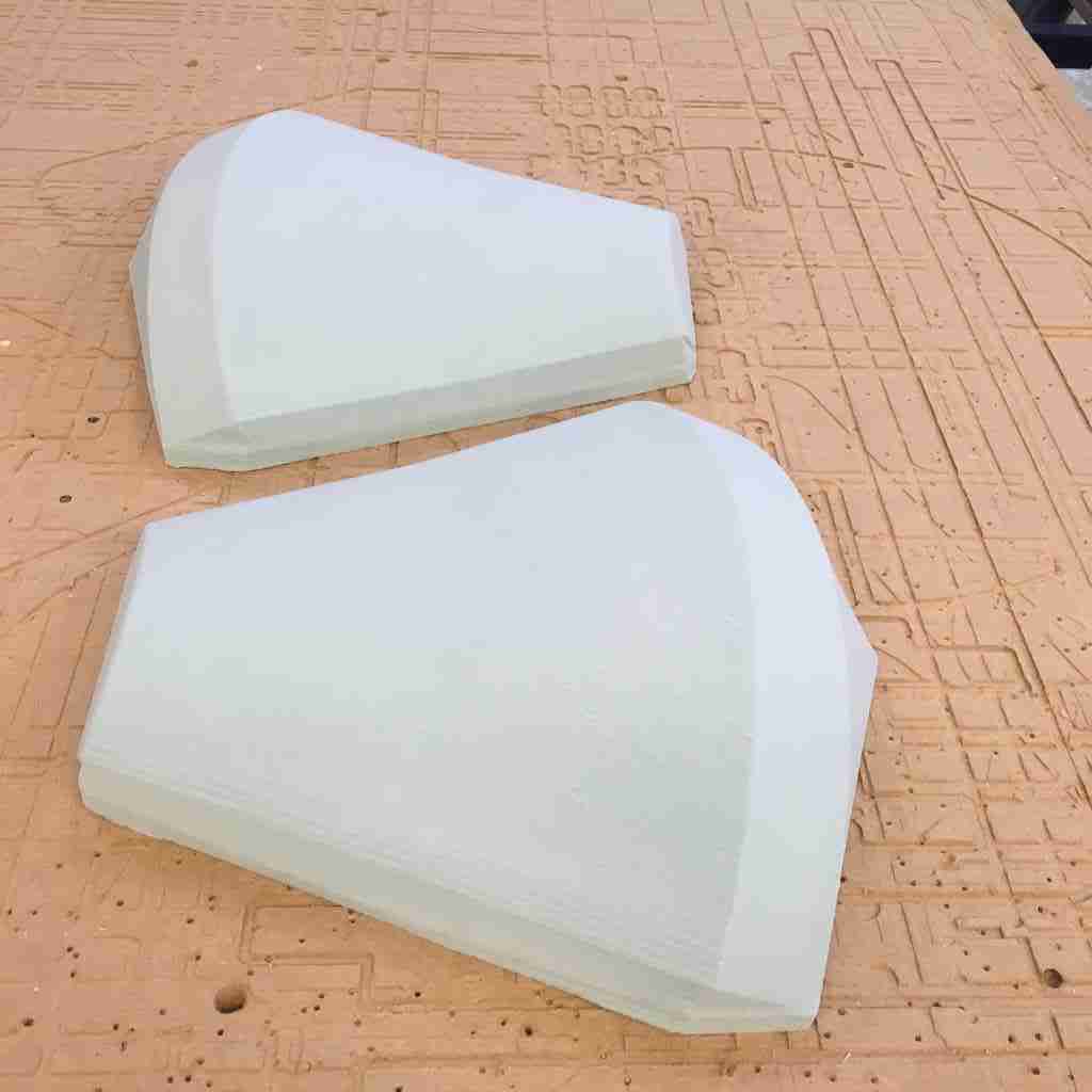
Designing a mold
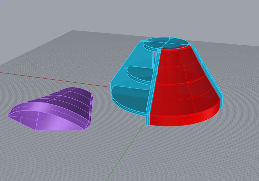
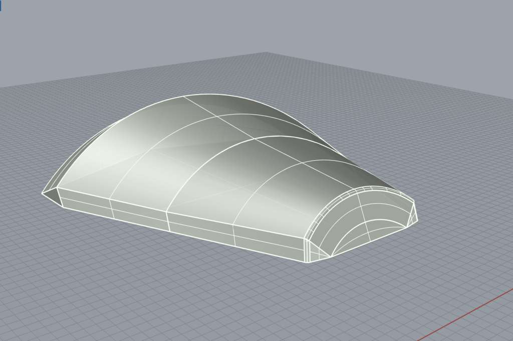
I decided to design and mill a mold from some left over rigid polyurethane foam that we have left over in the lab to make a composite casing for my generator housing. The foam was only 100mm thick, and although I could have possibly layered it to create a bigger mold, I had to take into account the Z axis limits of the Shopbot. This is why I decided to design quarter sections of the base casing, rather than a full half of the base which would have meant creating two rather than four composites. Instead with this design I was able to mill two molds which means creating two composites at a time.
 |
 |
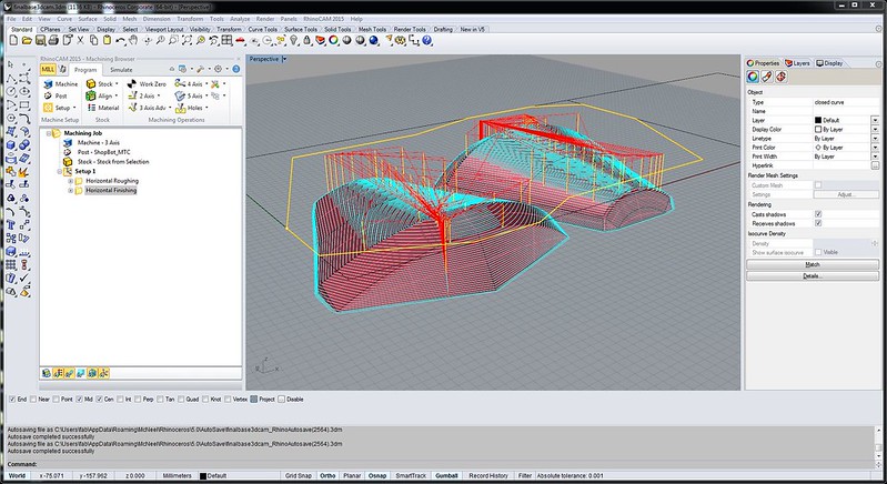
CAM Strategy
Again I used RhinoCAM to make my milling strategy. For the mold because I needed to mill a curved surface I used 3-axis milling option. Similar to when we were milling wax for the molding and casting week, this involved first a horizontal roughing and then a horizontal finishing strategy. The feeds and speeds were kept constant: 4000 RPM same with the plunge and engage because this is a relatively “soft” material.
The main difference was under Cut Levels > StepDown Control. This is the distance “step” which the tool takes to move down on the Z axis. We left this very wide for the Roughing at 30 mm and for finishing = 3mm, which for a 25 mm tool diameter was in retrospect a little excessive, but guaranteed a very smooth finish.
The most important thing here was to manually set the Z clearance plane (from automatic to 5mm) so that the ShopBot doesn’t slam into the Z limit while moving from point to point. Because I set the mold a little raised above the stock floor, I did not need to put tabs or bridges as the foam is relatively easy to cut out afterwards.
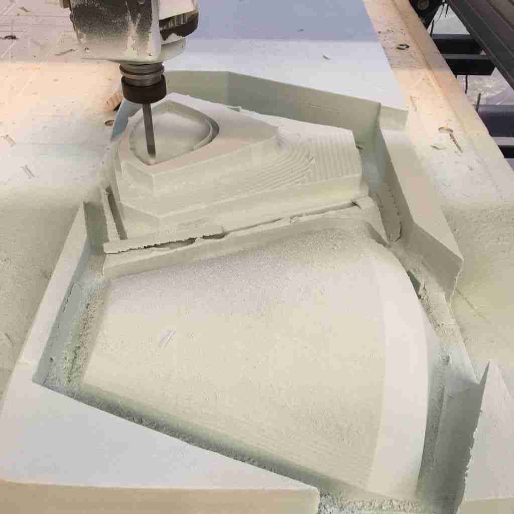
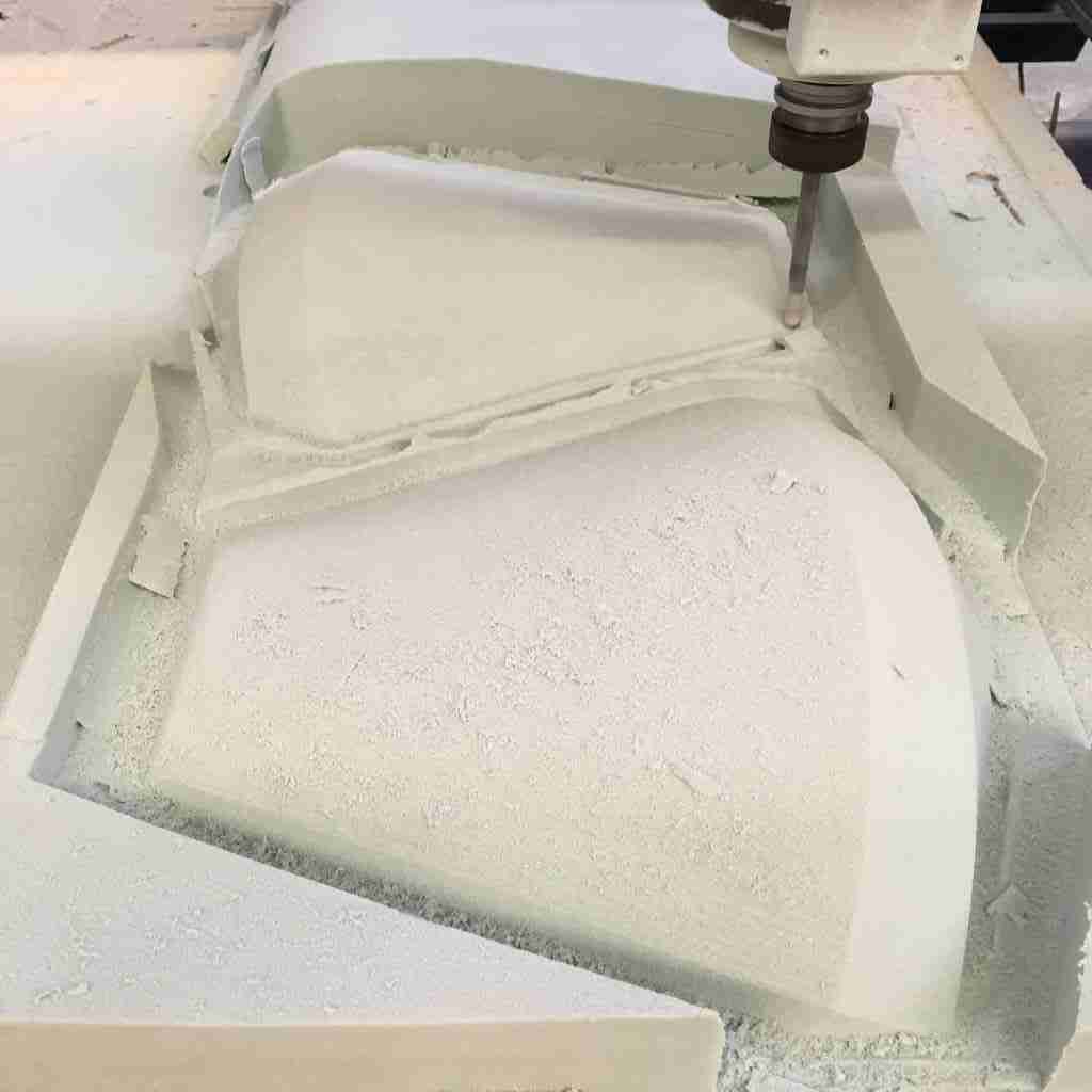
Milling
Rigid foam is a surprisingly easy material to mill in because it is soft and nothing can go too wrong if your tool plunges by mistake into the stock. Though the same milling precautions must be taken to avoid this. For milling, I decided to use a 10mm (2 flute) ball end mill and basically one horizontal roughing strategy (30mm step down) and one horizontal finishing (3.1 mm step down).
To get the material to fit on the ShopBot we had to unscrew the sacrificial layer otherwise, with 100mm thickness the Z axis had no room for manoeuvre. This wasn’t too much of a problem. Then to fasten the foam to the bottom I just used wood offcuts and screwed them in on all sides of my stock, creating a wedge so that it didn’t move. Here are some snapshots of first the roughing and then finishing:
 |
 |
Getting sticky
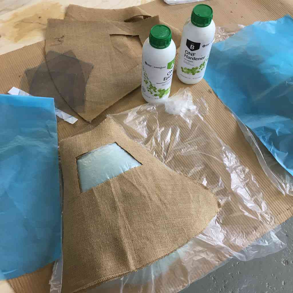
For our composite adhesive we used Super Sap Clear and hardener. This is a bio-based epoxy, and a general purpose laminating resin for composites, coatings, and other adhesive applications. The safety data sheet does warn of skin irritation and allergic reactions and cautions against breathing the vapours. This considered we wore gloves and worked with the resin in the spacious and well ventilated area of the FabLab.
Reading the technical data sheet plus some handy tutorials from our fab managers helped us in how to get the right mix ratio of 2:1 (2 parts Epoxy to 1 part hardener) and stirring the mixture in plastic cups enough to get the correct colour and viscosity.
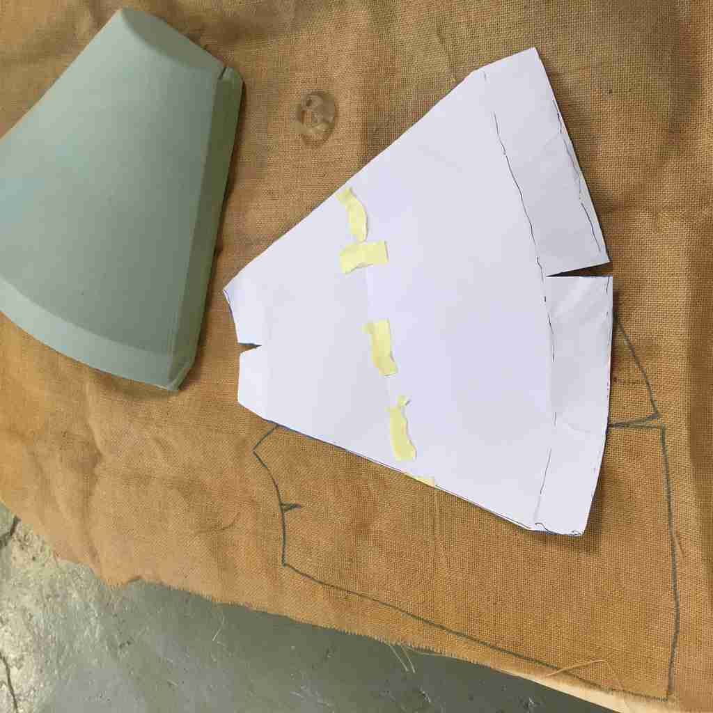
Layering the composite
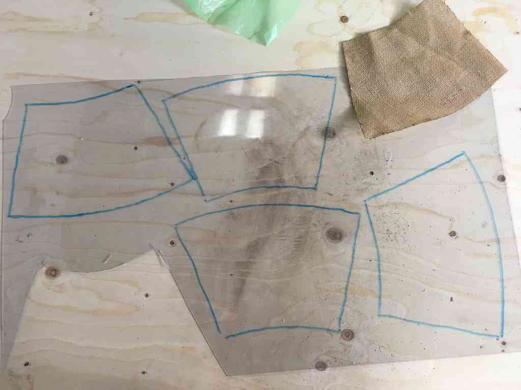
For the material of my casing I decided to test both the burlap material and some lycra netting. Originally, I wanted to laser-cut the material to precisely fit my mold surface but alas our laser cutters were all busy. So I resorted to tracing the shape on paper and using some digital fabrication rock, paper scissor techniques. Note my fabulous darts.
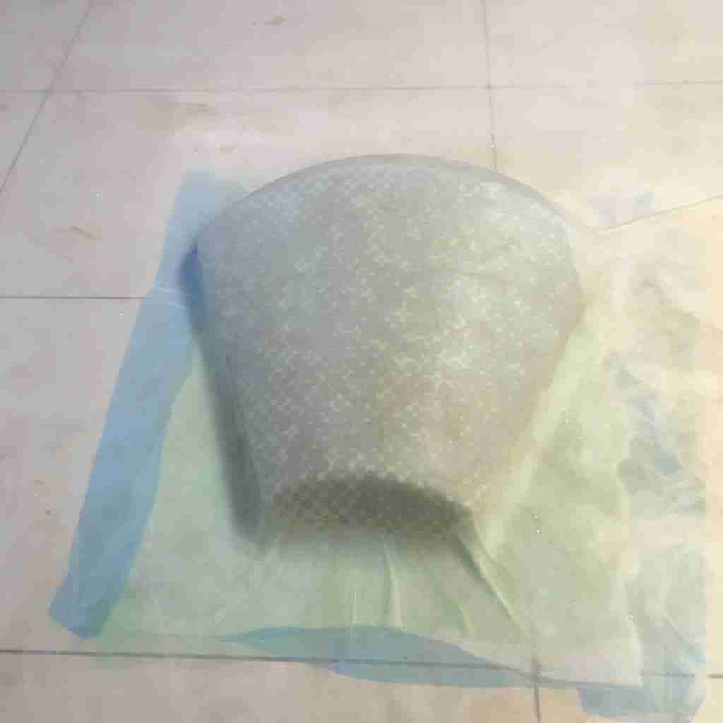
Because we were going to be using the vacuum machine to press our composites, layering plastic sheeting below and above the mould/composite was important to stop the resin from squishing out the sides and getting into the machine. The layering process went like so:
- Cut out composite layers and lay out the bottom plastic protection in the vacuum BEFORE mixing Epoxy.
- Wrap mold in thin plastic sheet (not too tight) to stop composite sticking to mold.
- Don gloves and mix Epoxy and hardener, ratio 2:1.
- Spread resin thinly and evenly on material. Layer on the mold.
- On top of layers place sheet of porous plastic followed by absorbent material.
- Remove sticky gloves and add top protective layer of plastic.
- Lay mould + composite onto preset area in vacuum machine. Seal and turn on vacuum.
 |
 |
First results
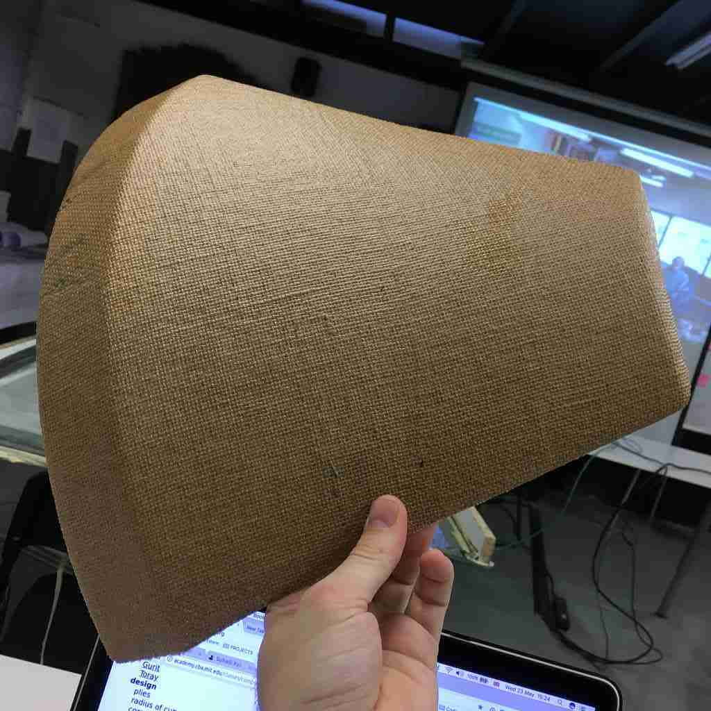
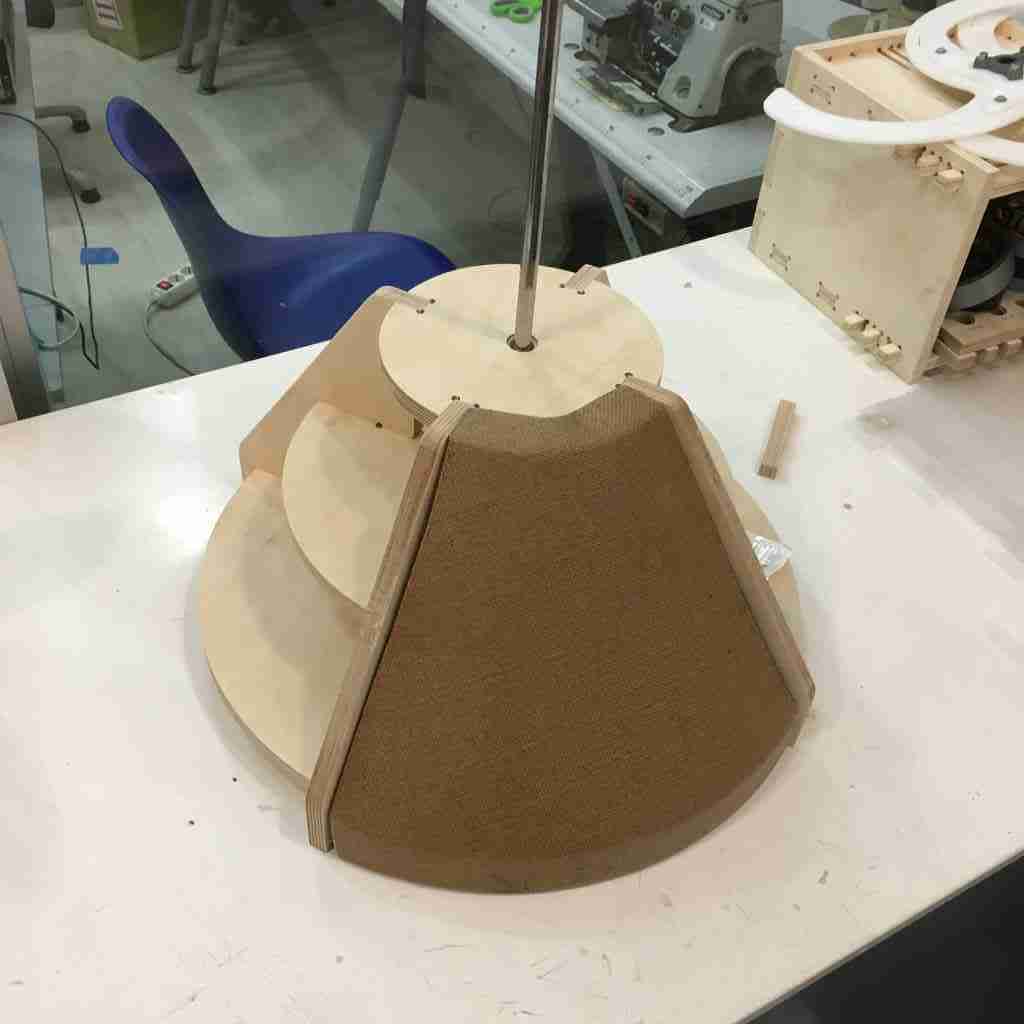
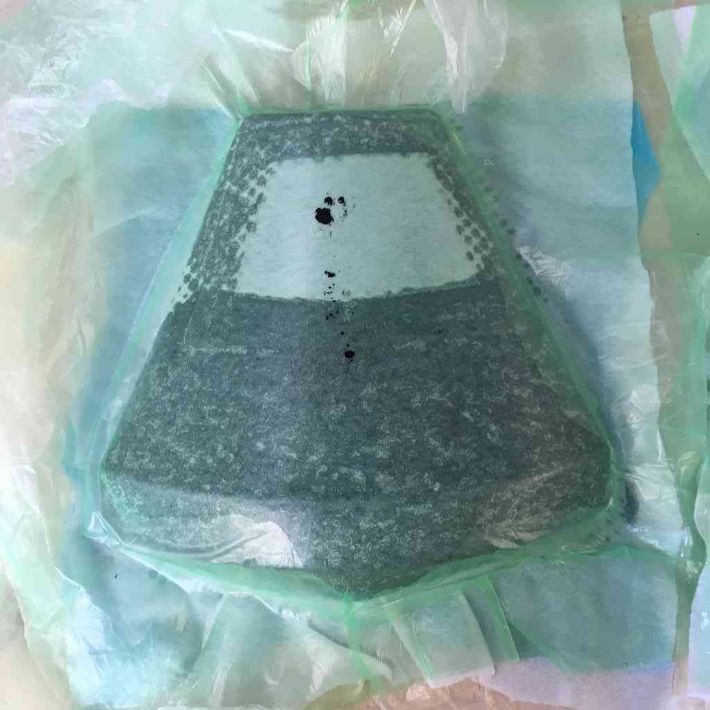
Below is the final composite from 2 layers of burlap, and it’s nice and solid. The lycra was disappointing and turned out to be floppy. A good sign during the vacuum is seeing dots appear where the excess resin has squeezed out of the porous layer into the absorbent material.
Also it’s important to try and make sure you set out the dry work space in the vacuum and have all you dry layers ready at hand before you get your hands sticky with Epoxy and avoid getting resin all over the machine.
Composite windows
I wanted to try and layer some see-through plastic we had in the lab to create a window in my composite which would serve to observe the inner workings of the generator, tachometer and other electronics.
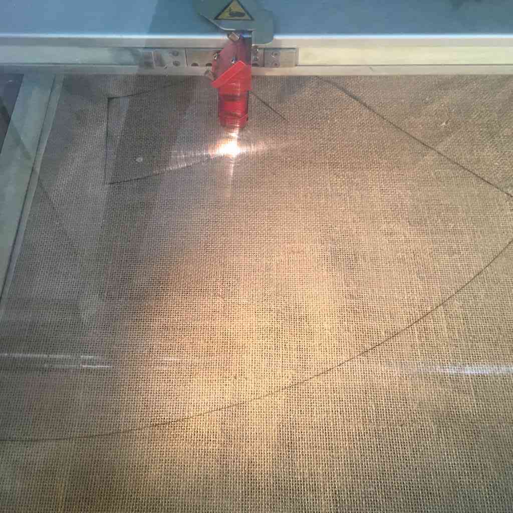
For this I needed to laser cut the burlap to make sure I got exactly equal size layers. For the the lasercutter I used the Trotec 400, testing the fabric settings with a low frequency and power and slowly increasing the power. This is a highly flammable material so I wen’t carefully at first making sure I didn’t get any flames. Finally, I found my optimal settings at:
Power = 40
Speed = 1.00
PPI/Hz = 1000
 |
 |
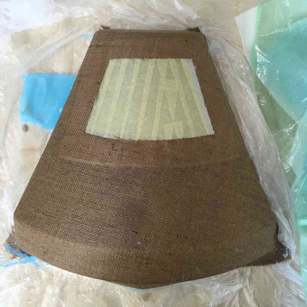
I took the extra effort of using the manual sewing machine in the FabTextile room to sew one side/seam of the two burlap layers together. This helped make sure that the layers remained aligned when I added the epoxy and the rigid plastic in the middle.
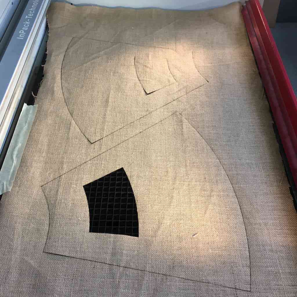
Below, I used the negative of the widow (with a 20mm offset) which I lasercut in the burlap to trace manually onto the plastic sheeting and cut it out by hand. I was not sure the exact properties of this material (nor did anyone else) and had a faint suspicion it could be a PVC derivate which risks not only ruining the laser optics, but also emits a noxious chlorine gas when cut! Also sometimes hands and scissors is just simpler, quicker and easier.
Before layering the sticky epoxy, I used masking tape to cover the plastic so that the resin doesn’t smudge and stick to the plastic under the vacuum. Once it is dry you just have to peel it off. After leaving it overnight to cure in the vacuum machine, here are the results:
 |
 |
And here the head strong bulletproof test. This would make great armour.

Conclusions
Over all I was very happy with my wildcard composite experiments. This not only provided me a lovely cover for my generator housing, but also was nice for the overall system integration of my final project. Burlap is a very porous and absorbent material to work with so to get a solid finish I would suggest being quite liberal with the epoxy.
As for layering the see-through plastic windows, this experiment worked rather well. Next time I would suggest sewing or fixing them between the layers first so that they don’t slide about under the epoxy soaked material.
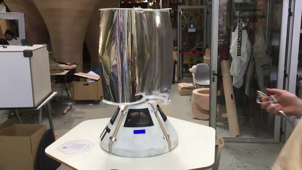
Finally although this was part of my project development week, I decided to spray paint the composite housing in white and vinyl cut some black window frames for a space-age aesthetic touch. I was going for the NASA Apollo missions look here :)
Here you can see what it looks like all assembled.
You can download all my CAD and CAM files for week 17 from my Gitlab repository.