
Week 03 - Computer-Aided Cutting
Laser cutter hype! This assignment taks about laser and vynil cutting machines.
Note: All the files here
Contents
Individual assignment
Below I will detail both, cardboard laser cutting and vynil cutting for this week assignment. For the laser cut of my individual assignment I focused on cardboard as a material and tested the kerf and built a press-fit construction kit. For the vynil cutter, I created a couple of simple stickers that I will detail below.
Laser Cut
For the laser cut machine I used the TROTEC Medium format Laser Cutter (Trotec Speedy 400) and 4mm cardboard as a material. This machine has 1000mmx600mm dimmensions.
After cutting the material to the maximum machine dimmensions and focusing the z-axis, I prepared a brief test for assessing the Power/speed trade-off of the material. As general guidelines, for this machine one should keep Speed<1, since it has a y-axis problem, frequency at approximately 1000Hz. Furthermore, there should be no flame coming out of the material while cutting and, of course, we have to cut it. Finally, it is recommended to keep as low as possible the power, in order to reduce the kerf.
After this test, for cardboard 4mm, the final parameters found were:
- CUT: Power = 25% power / Speed = 0.9 / Frequency = 1000Hz
- ENGRAVE: Power = 7% power / Speed = 0.5 / Frequency = 1000Hz
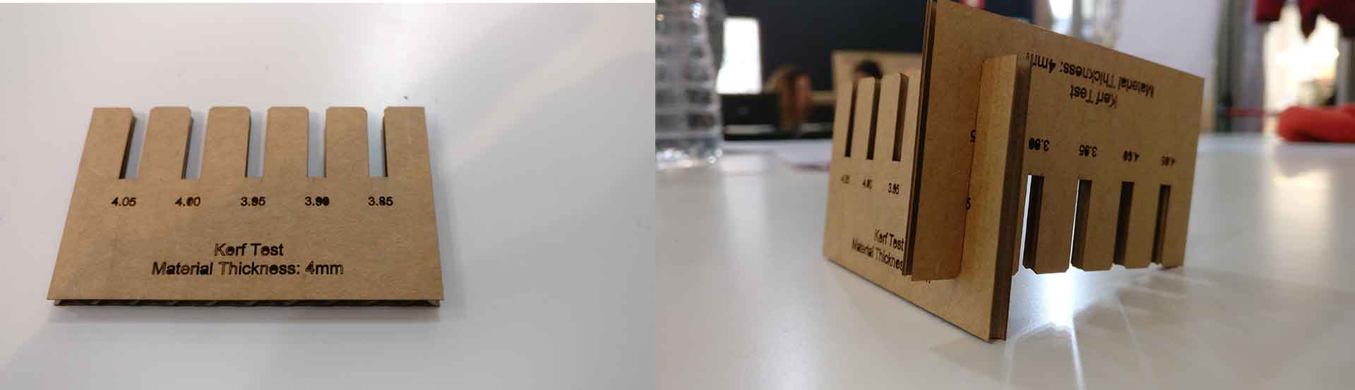
Kerf Test
With these parameters, I went onto creating a kerf test in order to assess how much the laser was cutting off the material, since the laser diameter is non-zero. This parameter is important for assessing how the press-fit construction kit should be defined, since the joints need certain pressure in order to act as press-fit.
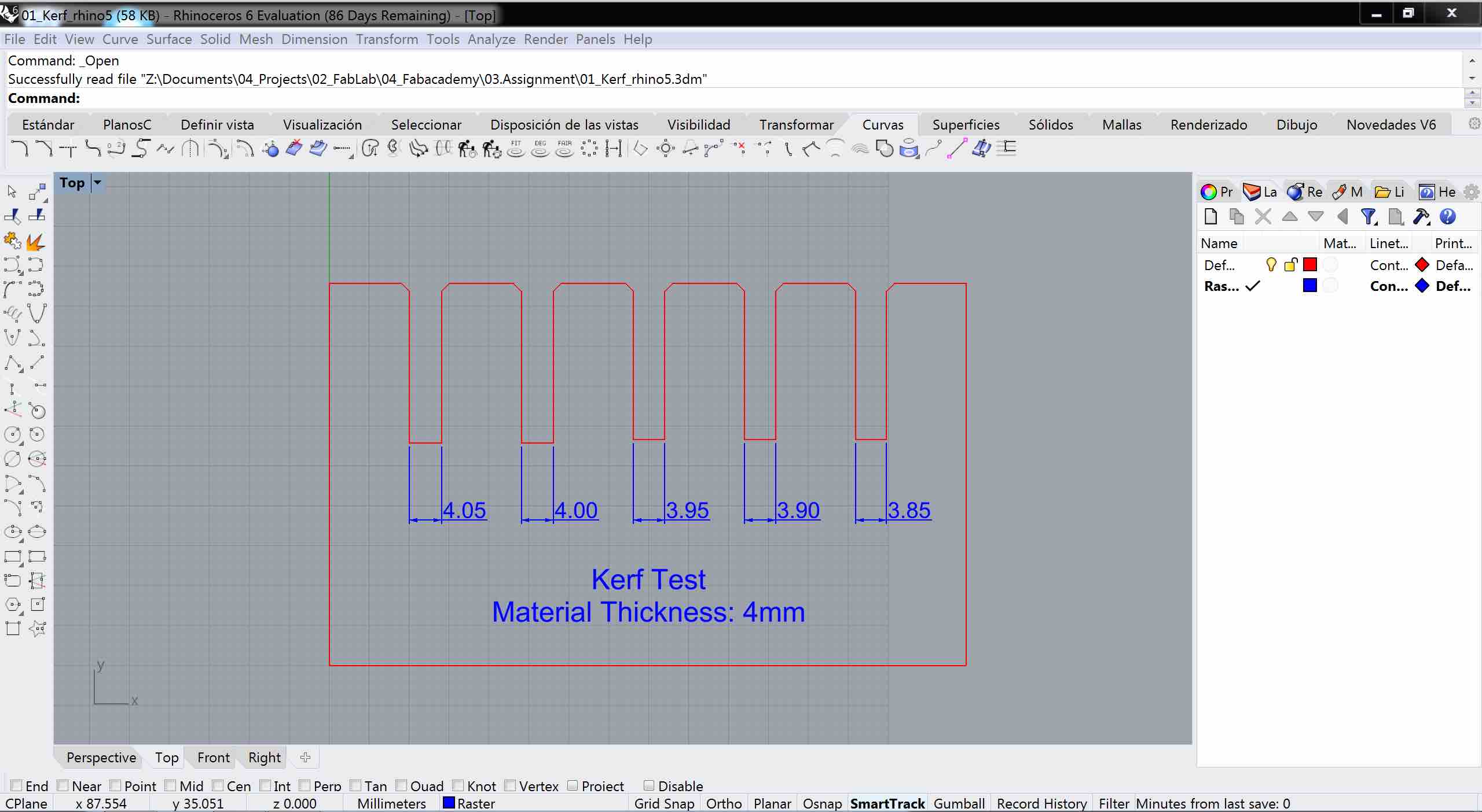
The red layer was CUT and the blue layer was set as ENGRAVE. The cut piece is shown below, being the final kerf selected for this material to be 3.85mm:
Press-fit construction kit
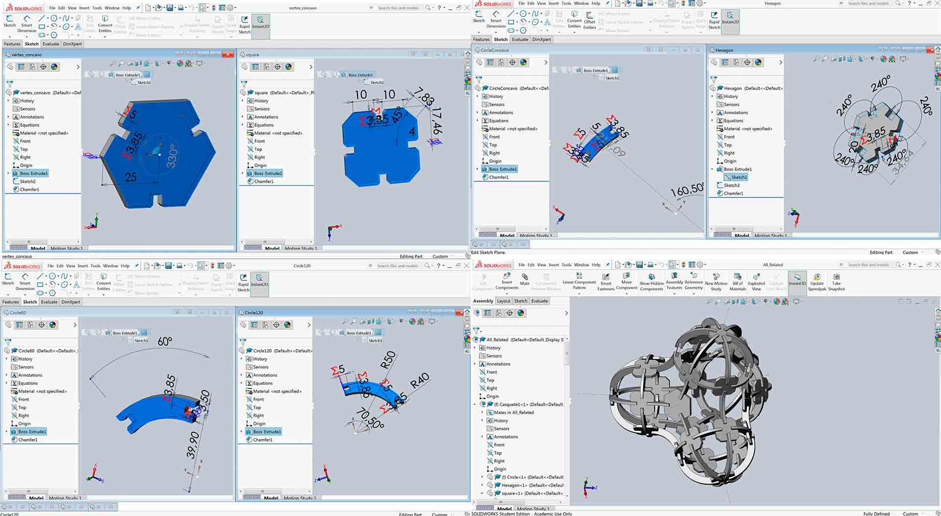
For this part of the assignment, I have developed a parametric model in Solidworks for a press-fit construction kit that ressembles other ideas, but aiming to design a thetraedron, instead. The result is shown below:
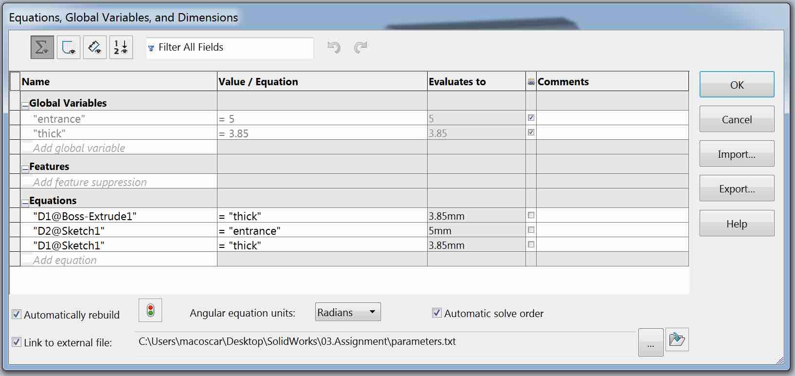
The parameters for this model are the thickness of the material (and therefore the joints) and how much crossing the joints have:
"thick"=3.85
"entrance"=5
These parameters were modified in the Tools>Equations… window in SolidWorks, linking to a external .txt file:
Some captures of the individual pieces are shown below:
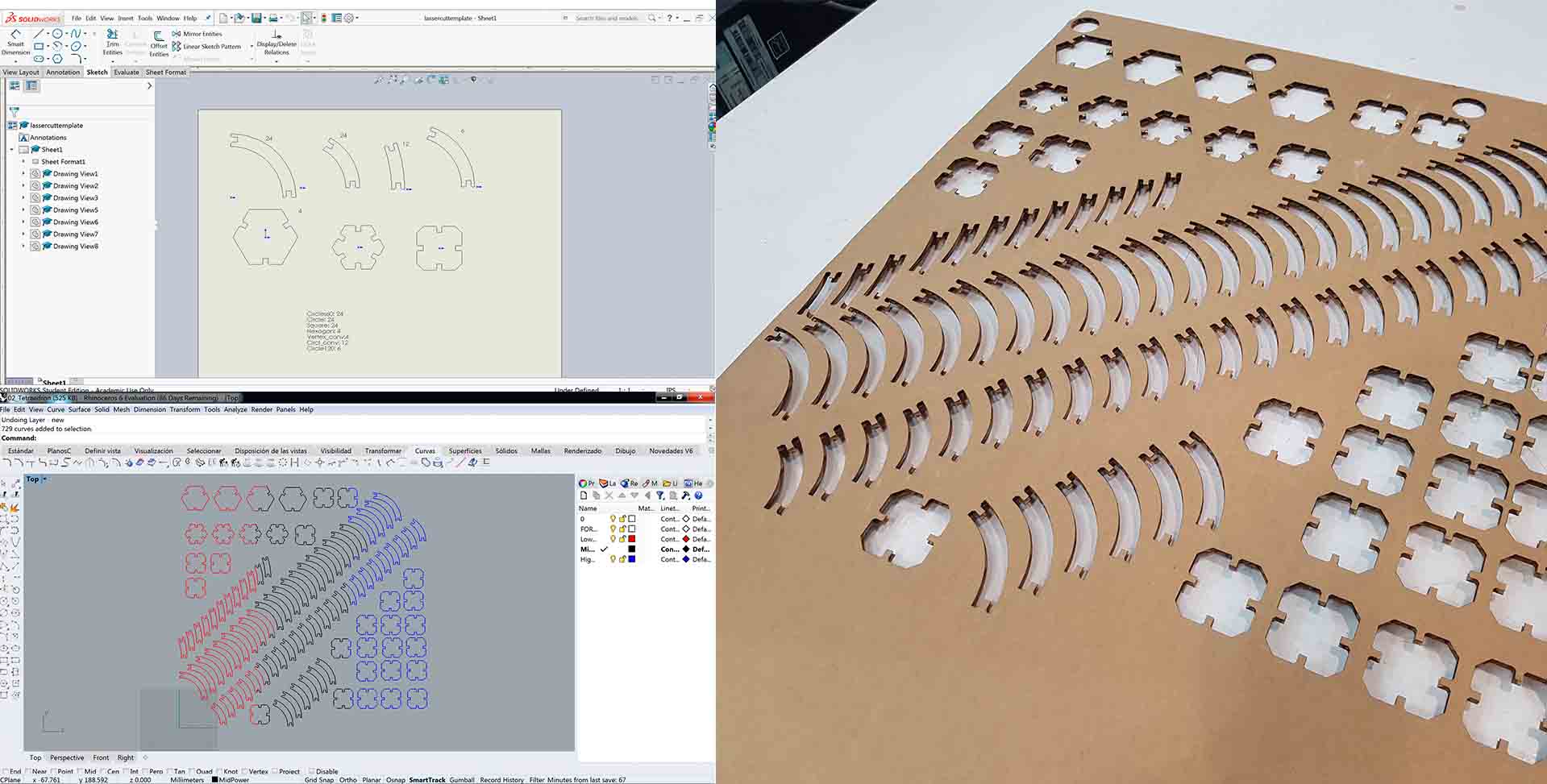
Finally, the top view of each piece was drawn in SolidWorks and from it exported to Rhino, where it’s easier to manipulate and create arrays, ready to print:
And the final result is:
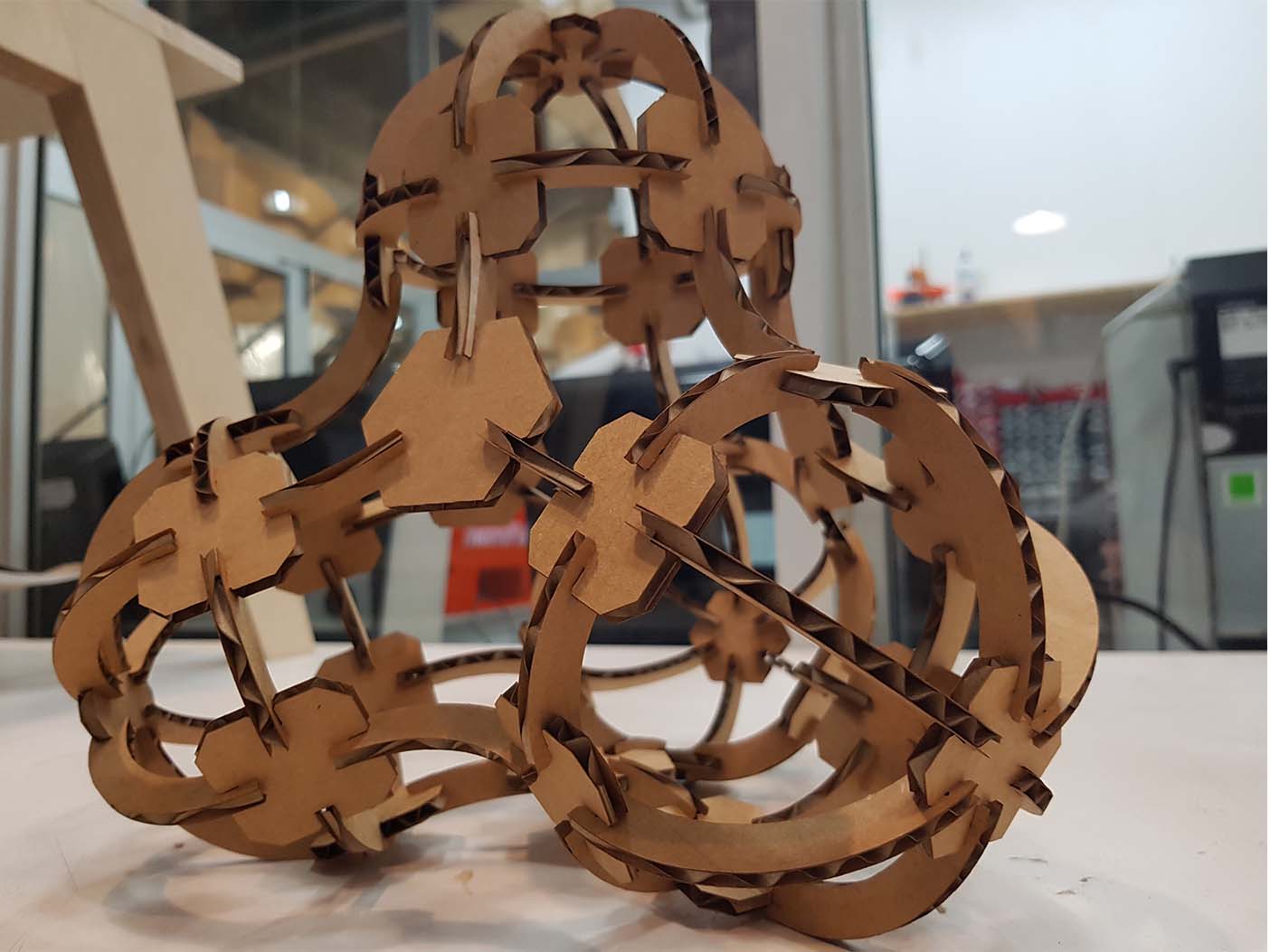
There are two problems with this design that could be improved in future iterations: first, how much the joints are interlaced, since 5mm is not enough for long-lasting joints. Second, the material is too weak in some directions, provoking the joints to bend and not be effective after a while.
Vinyl Cutter
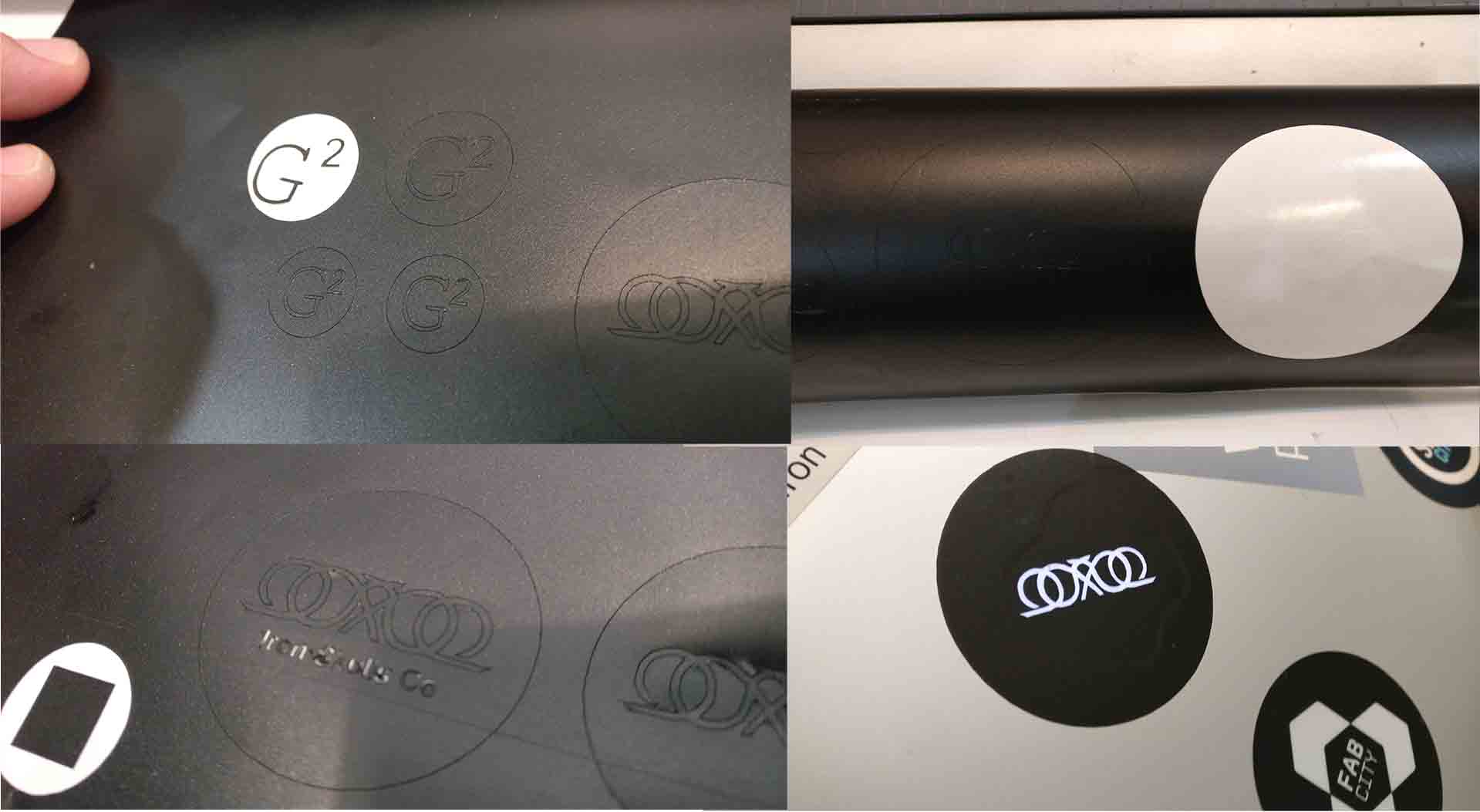
For the Vynil Cutter assignment, I created two simple stickers with two logos in Rhino. The more complex logo, was hand-made with a Polyline construction on top of a picture inserted with PictureFrame command.
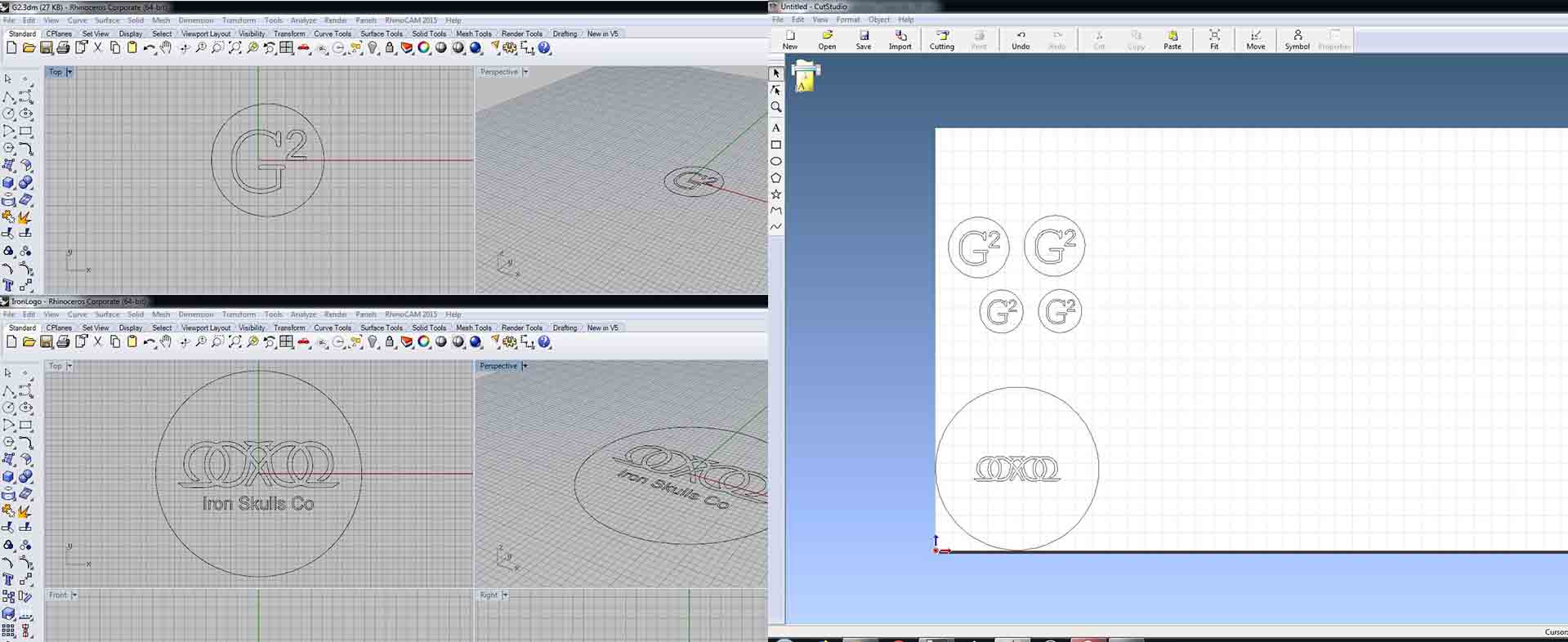
In the Roland Cutter I turned on the machine, placed a Piece of material and pressed with the rollers on the vynil. I used the default settings, but using Piece instead of Roll or Edge and pressed Test to check if they are appropiate. Being the test OK (the circle around the square is peeled off easily without taking the square with it).
The final result is shown below, which I put in my laptop covering the Apple logo:
Group assignment
During the group assignment we tested a generic template on different materials. The template was downloaded from the internet and adapted for our purpose. A capture of the template is shown below :
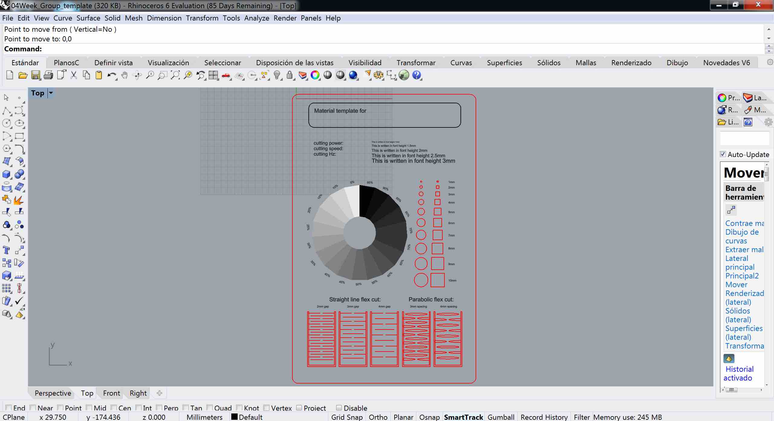
This was tested in cardboard and plywood. For each of those, we detail the results below. Before moving on, here are the links to my colleagues sites:
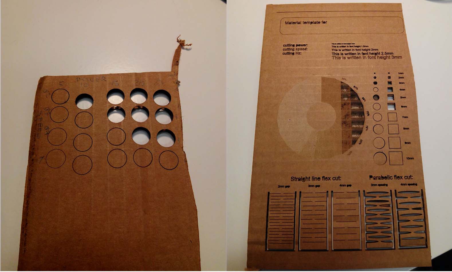
Cardboard
In order to assess power/speed trade-off mentioned above, we perfomed a variation with a simple rhino file with circles and different colors assigned to the materials. The final choice for this material was:
- CUT: Power = 30% power / Speed = 0.9 / Frequency = 1000Hz
- ENGRAVE: Power = 5% power / Speed = 1.5 / Frequency = 1000Hz
Once these parameters are set, we performed the test. All the lines in red are printed as vectors, but the circle for variable raster has a different treatment. Firstly, the areas in the circle are defined as hatches in Rhino. Secondly, they are assigned to different layers. Finally, each of these layers have a different grade of “blackness” in the grayscale, ranging from 0 to 255.

The job is printed from Rhino to JobControl as a vector, selecting the settings for the raster the Properties button. Furthermore, in JobControl the material is set with a high speed (Speed = 90) and the power in this trial is modified along the circle because it was substracting all the first layer. However, the power was not properly set in the final selection, since it didn’t cut through in all the pieces for both cardboard layers.
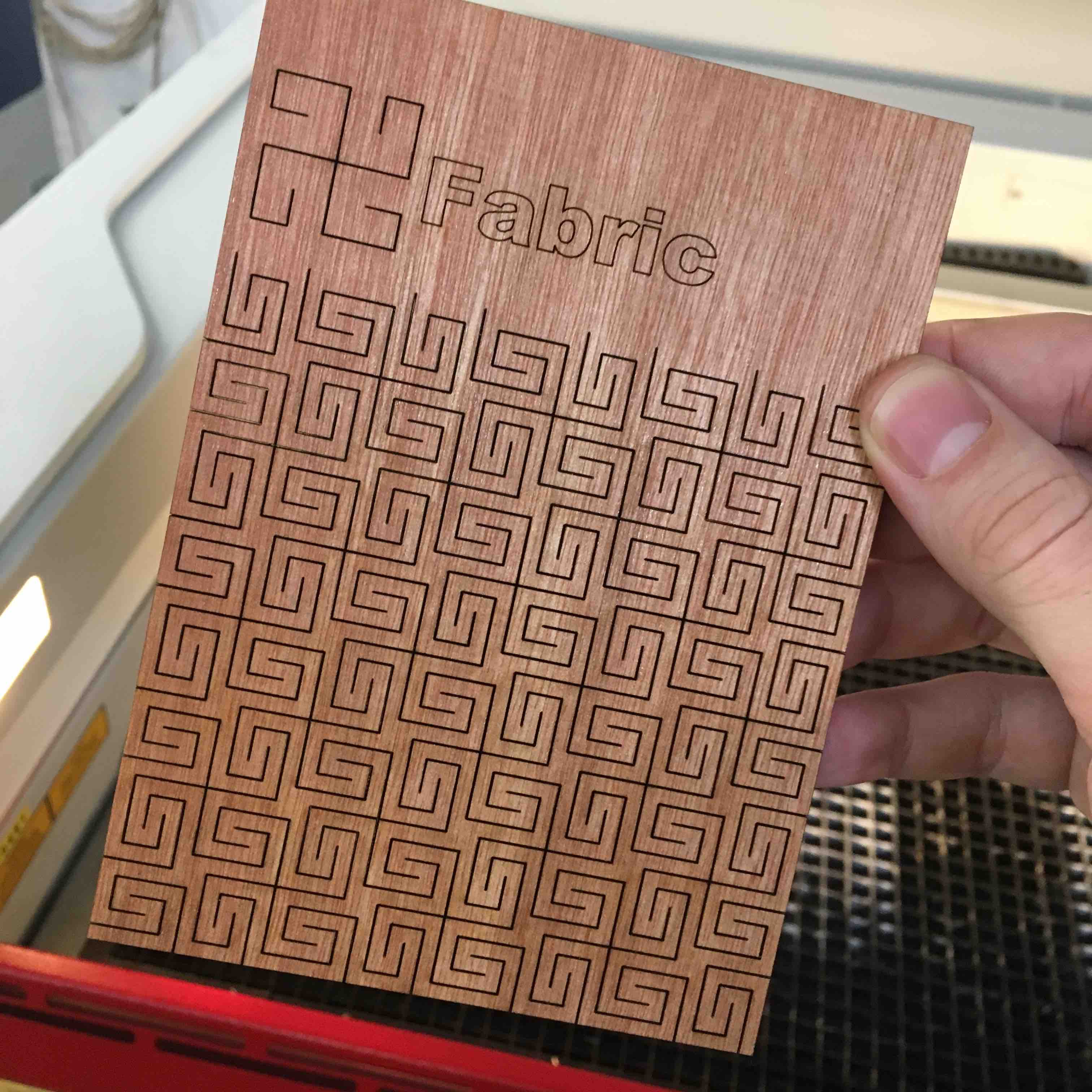
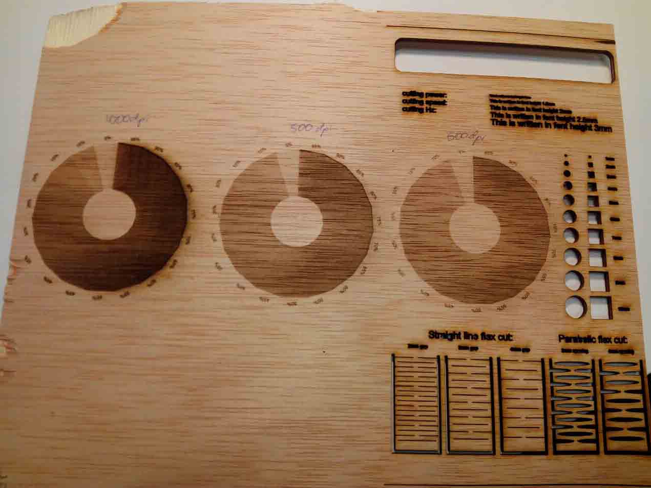
Wood
The same procedure was applied for the setup of power/speed trade-off, being the final settings:
- CUT: Power = 80% power / Speed = 1.5 / Frequency = 1000Hz
- ENGRAVE: Power = 30% power / Speed = 3 / Frequency = 1000Hz
The result is shown below. We performed several test for the engraving, varying power and resolution during the printing, resulting in different depths and colours, being the resolution as well an important variable to modify. From left to right below, the parameters variation was the following:
Left-most circle
- ENGRAVE: Power = XX% power / Speed = XX / Resolution = 1000dpi
Middle circle
- ENGRAVE: Power = XX% power / Speed = XX / Resolution = 500dpi
Right-most circle
- ENGRAVE: Power = XX% power / Speed = XX / Resolution = 500dpi
Extra ball
Living hinges test
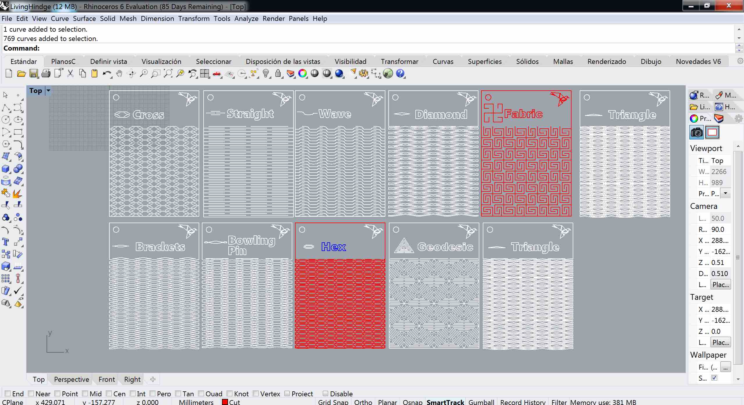
Additionally, with another colleague, we tested a set of living hinges downloaded in dxf compatible files. The set can be found under this link. We selected a thicker material for this trial: plywood 5mm. The templates are shown below:
Similar testing was performed for assessing the power/speed trade-off with the following parameters as a result.
First test
- CUT: Power = 75% power / Speed = 0.5 / Frequency = 1000Hz
- ENGRAVE: Power = 30% power / Speed = 0.7 / Frequency = 1000Hz
This material cracked easily with such a little thickness:
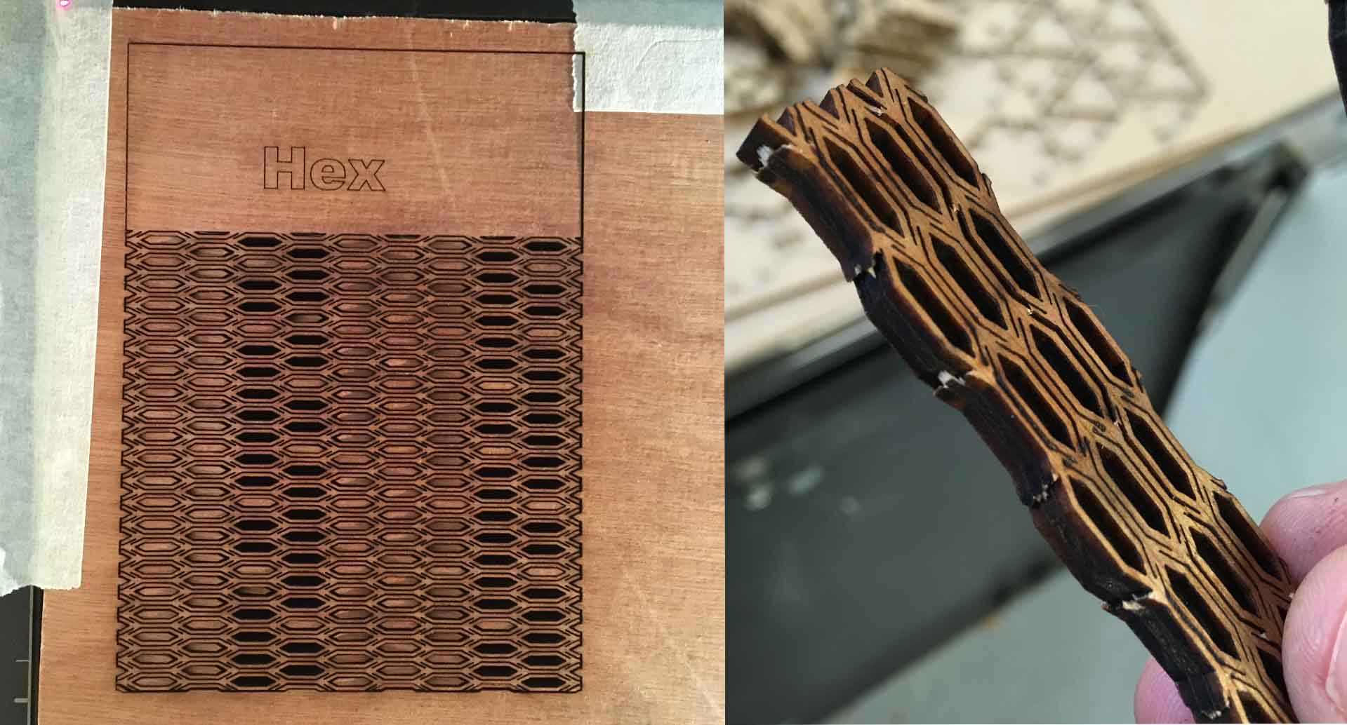
Second test
- CUT: Power = 65% power / Speed = 0.7 / Frequency = 1000Hz
- ENGRAVE: Power = 30% power / Speed = 0.7 / Frequency = 1000Hz
Being the second more successful: