
Week 07 - Computer-Controlled Machining
Make Something BIG!
Note: All the files here
Contents
- Contents
- Wood and tools
- The Machine
- Design
- G-code generation
- Cut in the CNC
- Mistakes!
- Final Project task
Wood and tools
Before jumping into the design phase, let’s review what tools and materials are available in for this assignment. For the wood stock we will be using boards of plywood 2500x1250mm of 15mm and 9mm thicknesses. The CNC we’ll be using is the ShopBot Milling Machine, with a flat single flute CARBIDE mill with the characteristics I detail in the RhinoCam section. From this, we have to keep in mind that these parameters will be important for our design and the G-code generation.
The Machine
As mentioned above, the machine that we will be using is a ShopBot Milling Machine with 96x48x8in (XYZ) or 2.44x1.22x0.2m bed. The axis are represented as follows:
Image Credit: Shopbot tools
All the information about the machine can be found in this brochure and on Shopbot’s site. The machine’s manual can be found in this link.
There are two software needs for the ShopBot: the one that will create the strategy and likely where we would make the design at, such as RhinoCam, Fusion 360, V-Carve and so on and that will export the files to a ShopBot compatible file (* .sbp). The other one is the ShopBot Control System that can be downloaded from the site. This program will be the one commanding the actual machine and sending the actual G-code instructions.
Finally, last but not least, we should know where the safety knobs for the machine. The controls also for the spindle and the global switch should look something like this:
Design
For the design, I will be using Rhino, in combination with Rhino Cam for the Gcode generation. What I would like to make is a shoe-shelf for my appartment, somehow similar to this design from OpenDesk. However, I would like it to be modular and below there is screen capture of the concept in Rhino, as well as some pictures of my drawings on my notebook:
The total depth would be 400mm and the width 900mm, being each module would be 300mm tall, with the possibility of splitting the inner space into two 150mm shelves. Below, I detail the types of joints I will be using (from OpenDesk):
The 2D design is done in Rhino, and the layout would be the following, in two boards of plywood, one 9mm (below on top) and the other 15mm thick (below in the bottom). With other colleagues we tested how narrow/wide the pockets should be done, and on average we consider 0.15mm in extra to the material thickness on each side should make a good fitting (therefore, a 15mm pocket would turn into a 15.3mm considering this):
In Rhino, I have splitted the content into different layers for the different cut heights and strategies in Rhino for clarity. Note that there is one dedicated layer for the STOCK and another for the SCREWS.
At the time of writing this assignment, I am planning to make one single row of the bookshelf, but the idea would be to create a stackable system with several layers.
G-code generation
In order to generate the G-Code I will be using RhinoCam. The first step is to check that all the points in our design are in the same layer, as well as having the design with the bottom left corner down in the [0,0], with the longer axis matching the x-axis of Rhino (because the Shopbox x-axis is the long one).
Next step would be to generate the Stock of material we have. In this case, I will be first cutting the 15mm board. One of the layers of my design contains a rectangle with the base material stock, which we have to extrude down to -15mm (in the negative direction of the Z-axis):
Now, in order to generate the different strategies, we will follow this workflow:
- Generate marking points for the screws
- Generate drills for the dogbones
- Generate non-cutting through pockets
- Generate cutting through pockets
- Generate outline cuts
Tool and chip load calculation
For cutting the plywood, we will be using a flat end mill ø6mm, with a single flute. The tool used is already set in the Lab’s RhinoCam workstation:
Thip speed calculation is done based on the following formula:
Recommended plywood chip loads can be found online, for example in a manufacturer’s site. For a 6mm, single flute mill, a recommended chip load could be of 0.011in/flute, and with the traditional 12000rpm, this gives:
With this, a final value of 3000mm/min is chosen for simplicity and input in the RhinoCam. A screen capture of the cuttting speeds is shown below:
Screws
They will be done with an engraving with 5mm cut depth. Nothing particularly relevant for them, except that there is a sorting applied for the trajectory as below (it applies to all the strategies):
Dogbone drills
They will be done with engraving in two separate steps: 7.5mm cutting for the hidden fingertip joint tenon areas and 16mm (1mm more than the actual material depth) for the rest. Everything is basicly as the screws, except that we will be cutting in steps of 3.75mm for the 7.5mm (so 2 steps) and 5.34mm for the 16mm depths (so 3 steps), in order to not cut more than the tool’s diameter.
Pockets
They will be done with 2 1/2 axis pocketing. The same philosophy applies as with the dogbones: don’t cut more than the tool’s diameter. We will be using a 70% overlap and we will be starting the pockets from the inside.
Additionally, we will include an in-profiling in this area, in order to have a better finishing
Profiling
There are two strategies that will be done with profiling: the exterior cuts, with an out-profiling and the very thin pockets with an in-profiling. The latter are done in this way based on recommendation, in order to have a better tolerance in these areas, and also taking into account that material that will be left in between the cuts is only 2mm thick. Both of them will cover the whole material thickness with a 16mm depth cut, being the exterior cuts the only ones that will use 2500mm/s for all the cuts, instead of 3000mm/s. An image is shown below for the profile-in:
And for the profile-out:
Also, in the exterior cuts we will be using 8x8mm bridges:
Cut in the CNC
For the ShopBot, we have to do Post in RhinoCam and generate the G-code for the machine. The file type should be Shopbot_MTC (* .sbp) and in order to generate the strategies, we should create separately both, the Screws strategies and the Rest (since in this case we have no tool change).
Once we have saved the code, in the ShopBot control, we make sure of the following:
- The material is on the machine, in a flat surface, with the sacrificial layer below
- The machine is ON with the Spindle set up manually to the desired value (in my case 12 krpm)
- The air compression is ON (by opening the valve on the top of the head)
Fit the tool
Then, we can put in the tool, which should have been checked previously by someone with more experience than us. The tool is held by a pneumatic system, which is activated by the computer itself. The interface in the computer looks like this:
In the right hand side, in red, we have the position controller. In here, we have several options, and we can see where the machine is at the moment. In the Output area, we can click 3 and we will fit the tool. For this, we need to hold the tool by hand in the spindle and press at the same time. The pneumatic system will hold the tool in place and it should rotate freely without effort.
Zero Axis
We first find the end switches from the machine by going to the ShopBot Console and hit Cuts > C3- Home X Y axes using Prox Switches.
Now, in order for the machine to know where the zero of our piece is, we will use the yellow keypad in the picture below:
We will use this keypad to make zero in the X and Y axis:
The Z-axis is done with the help of a conductive plate that the machine will look for with the C2 instruction (Found in the Shop Bot Control under Cuts > C2 - Zero Z Axis w/Zzero Plate. Basicly, the machine will seek to touch this plate by moving down the Z axis and hit twice the plate. This is sketched below:
Image Credit: Shop Bot Wiki
Cutting
Once we have this setup ready, we can perform the marks for the screws to go in and drill the material down, without moving it! (otherwise we would loose the x-y axis homing). In order to do this, in the ShopBot Control System, we load in the SBP file we generated before with RhinoCam and we follow the next sequence:
- Check the spindle speed at our desired value (12000rpm in my case)
- Hit the green button in the control to start the spindle
- Put on safety glasses
- Skip the error that appears (apparently is normal)
- Press OK and start cutting
Then, we can launch the job for the rest. I did not take any pictures during the process, but this should be the result for one of the layers of the shelf!:
Mistakes!
And now, some mistakes and their solutions:
- I miscalculated the Hidden Fingertip Tenon and could not join “invisibly” both edges. After cutting with the manual tools available, I had to glue together the joint in order to be stable, since otherwise it would fall apart on the sides
- The interior pocketing it’s ok, but it needed some sanding by hand for it to fit properly
- The 8x8mm bridges should be done bigger and more frequent for the big pieces, since the piece movement can break them and create splinters on the visible side of the material
- In this design, we cannot stack together several layers unless we have different side panels, which will be changed for the next version
Final Project task
Note: All the designs below are available here
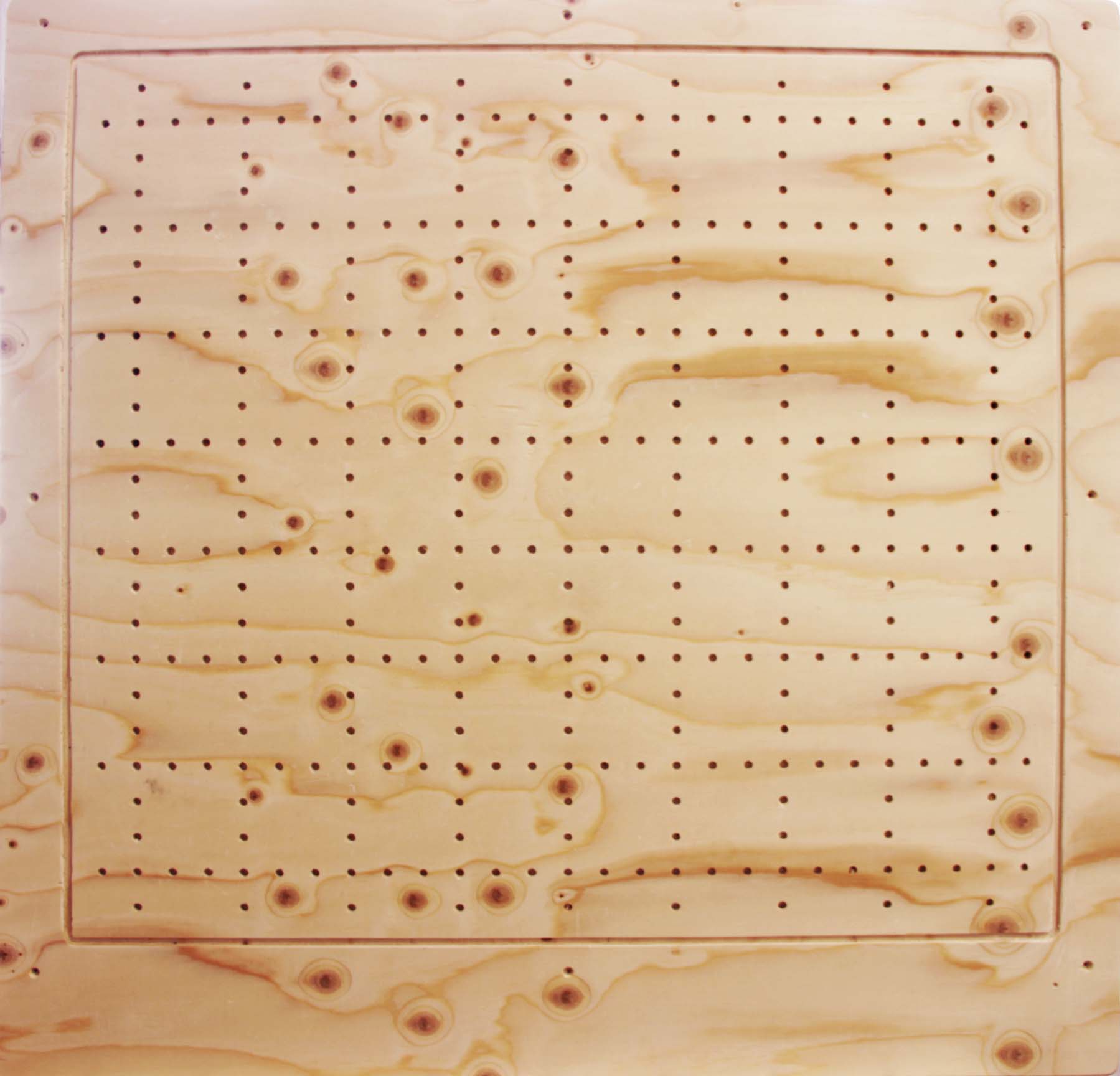
Here, I will be cutting an additional board of 90x90cm to serve as a bed for the PTFE blocks on my Final Project:
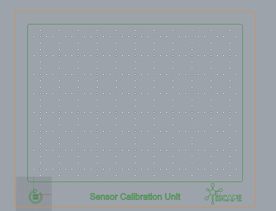
Using the same parameters as above, I will be doing the following:
- Plunging with engraving on each of the holes/drills for the tips
- Profiling for the border
- Exterior profiling for the cutout, with bridges
The result looks like the following: