WEEK 4: COMPUTER CONTROLLED CUTTING
Day 1
I found the class riveting. This is exactly what I was hoping to learn at the FabLab.
Since I’m interested in origami, I’m instantly drawn to the Vinyl cutter. Let’s see how long that lasts. Neil explained that with it you can control the force it pushes down and how fast it cuts. That is exactly the kind of control I’m looking for, even if it requires more tinkering and testing to get it right.
He also mentioned a number of materials that I’m dying to try out. 3M 1 Epoxy, for instance, which is a cast of epoxy film that is stronger than vinyl and tolerates higher temperatures. I’ve never worked with vinyl before but I’m looking forward to try out both. He also mentioned a transfer adhesive that is in stock at the FabLabs; it doesn’t stick to a primary material.
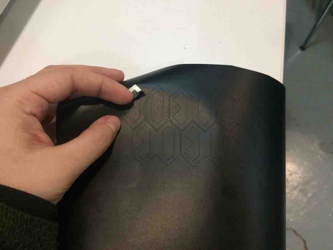
He also mentioned a technique called weeding, which is exactly what I thought of doing for my lamp project. I was thinking of making a foldable bookmark-lamp. It’ll probably become my Vinyl cutter project, I’ll have to ask if I can get a but ahead of the program and get help designing a simple circuit for a lightbulb. I’ll have to ask if they have tiny flat led’s and a tiny, flat battery, as well as some kind of flat conductive magnet.
I’m still unclear on what the group project entails.
Day 2
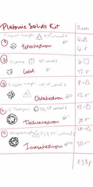
For the press fit together construction kit I want to make a Platonic Solids building kit. It should work in such a way that smaller squares can build different square sizes by adding them up and the joints should work for both forming bigger shapes and joining the pieces at an angle.
Day 3
The basic planning for the Platonic Solid kit is done, it should be simple enough as there are only 8 shapes that need to be designed. A regular triangle, a square and a regular pentagon, and then the five pieces that will put them together, which need different degrees to make the actual solids.
If I have time I’ll try to make cut a cardboard press-fit stool with the remaining 1x1m piece.
Day 4
Assignment:
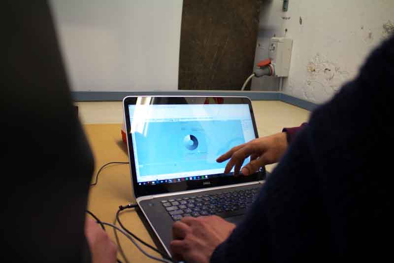
FreeCad is a nightmare. I don’t think I’ve ever encountered such a counter intuitive program. The problem with my old but wonderful computer keeps on giving. Since I can’t download SolidWorks or Fusion360 I’m stuck with it.
I decided to go ahead and design the stool in Illustrator and try to import it as a svg file.
Two options came up:
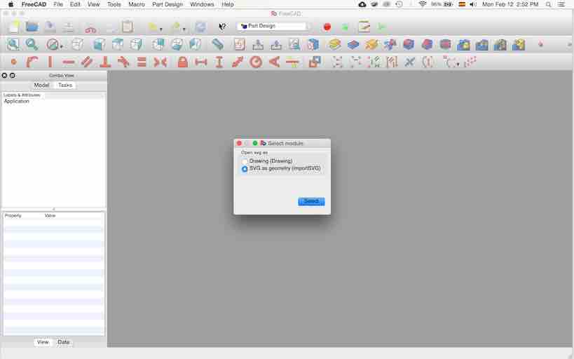
When I chose drawing the design became useless. I couldn’t modify it nor draw over it.
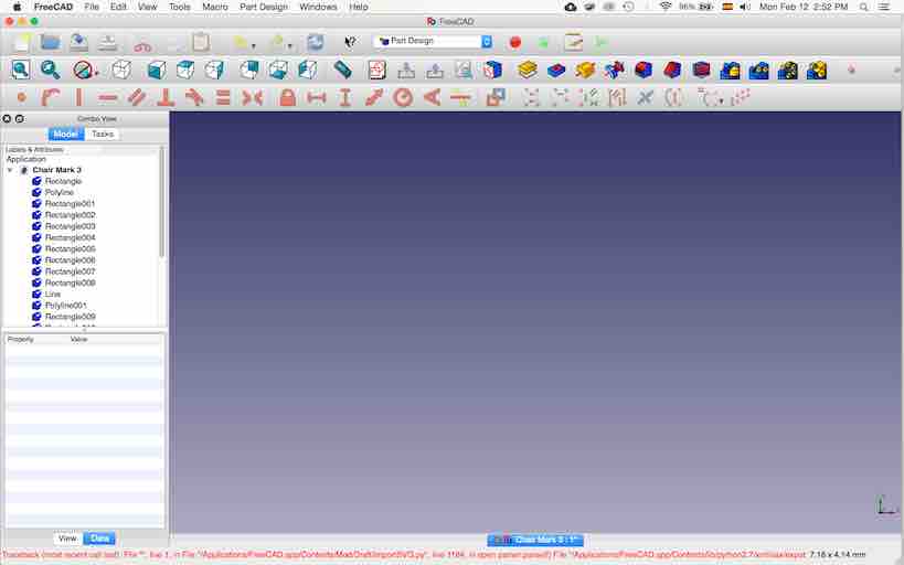
The first time I chose to open as svg geometry this error came up:
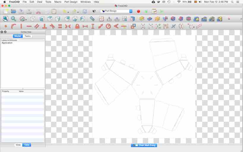
The second time only part of the design came through. It would allow changes, but not the parametric changes I was hoping for.

For some reason, I can’t find a tutorial on how to make variable parameters in FreeCad. It allows for distance references and length parameters, but it wont let me reference another line or the length of that line as a parameter for another line or object.
Day 6
Turns out the group project only entails basic testing with the laser cutter.
My team mates were:
Óscar González Fernández
Andrés Tuells
Javier Albo
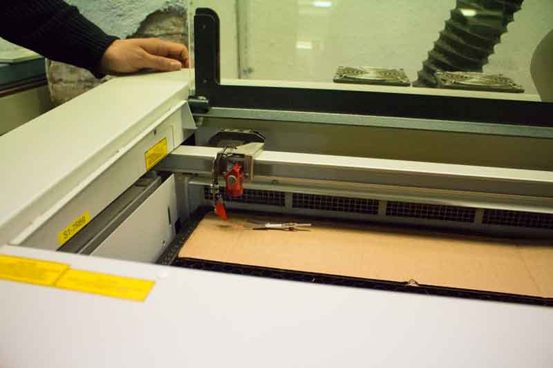
The machine in question was a TROTEC Medium format Laser Cutter (Trotec Speedy 400) that has has 1000mmx600mm dimmensions.
I couldn’t upload the entire documentation for our testing work but here’s some of it.
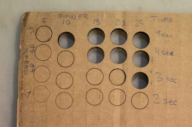
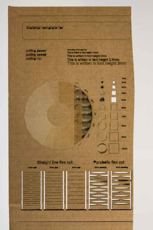
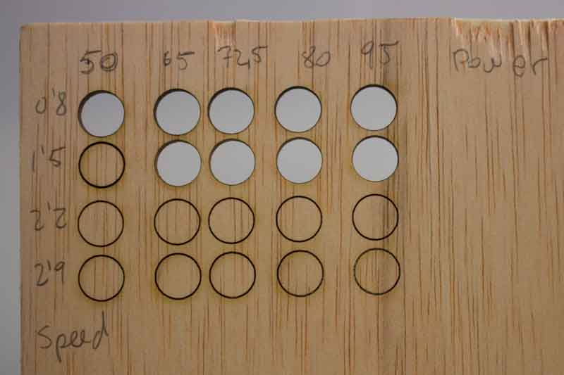
Initially we did a bunch of testing to see the relation between power and speed. Frequency we left at 1000HZ, as we thought that would be the standard and it shouldn’t be changed unless you really know what you’re doing.
The results were the following:

Initially we did a bunch of testing to see the relation between power and speed. Frequency we left at 1000HZ, as we thought that would be the standard and it shouldn’t be changed unless you really know what you’re doing.
The results were the following:
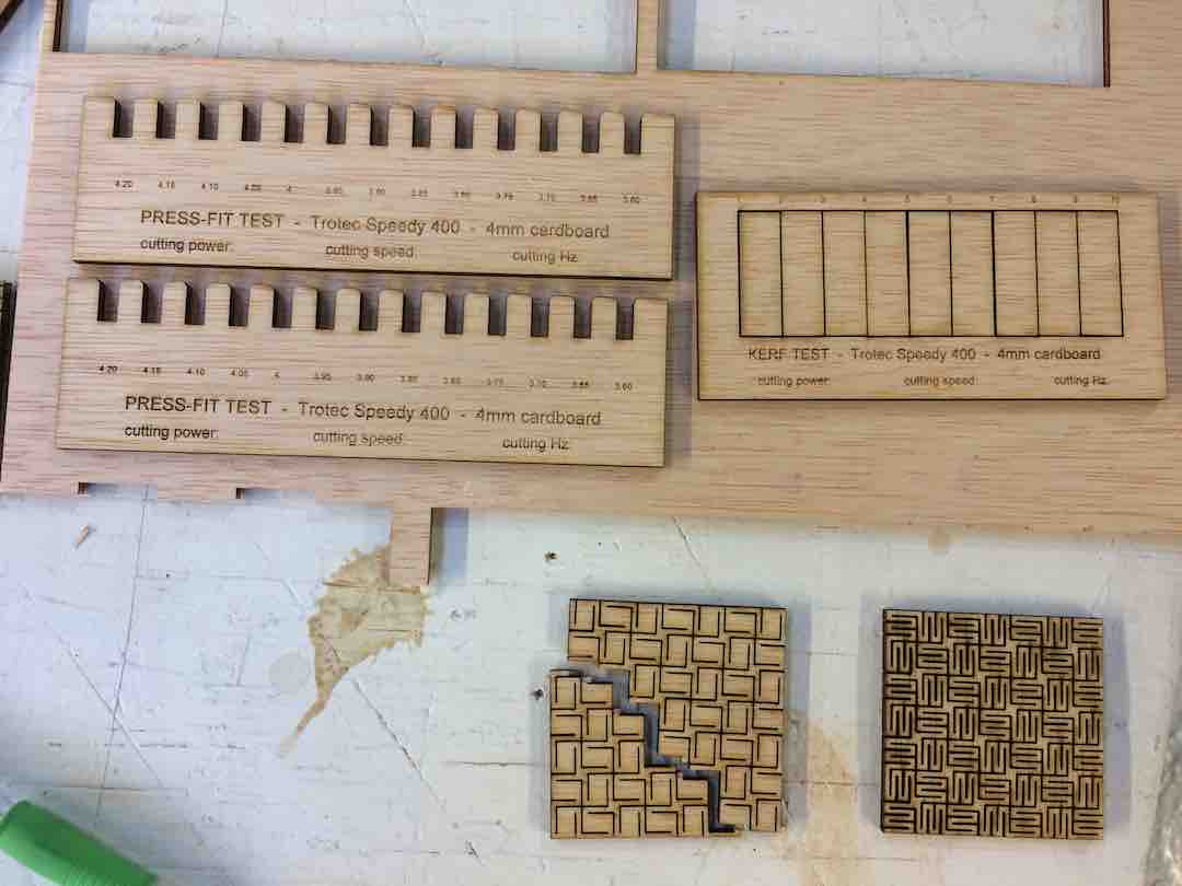
The best results for cutting 4mm cardboard was Power: 80; Speed: 1.5; Frequency: 1000Hz.
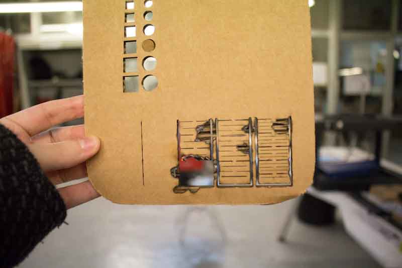
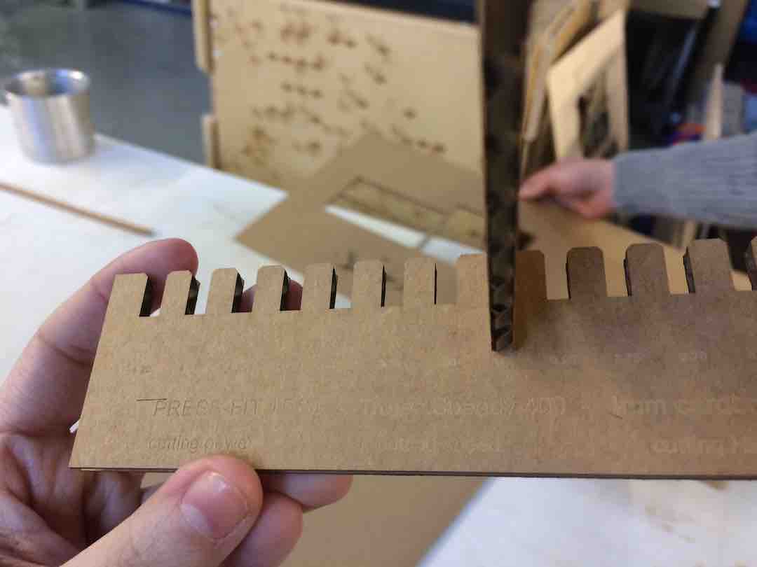
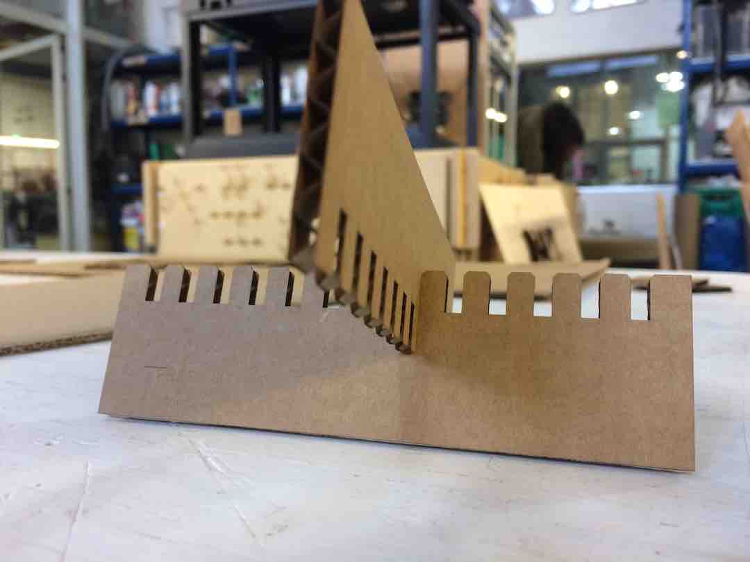
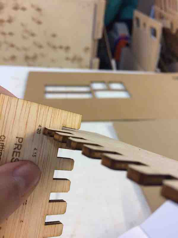
With this in mind we did our Press fit and kerf testing.
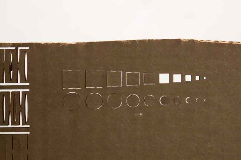
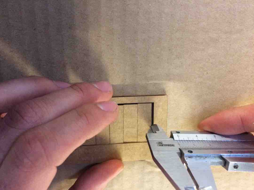
The press fit cardboard test turned out well. My prefered fit was the 3.85mm as opposed to the 4mm
The kerf we measured between 1.2mm -1.5mm/10 (it wasn’t terribly accurate)= 0.12mm-0.15mm. We should have tested 15 or more rectangles to get a proper measure.
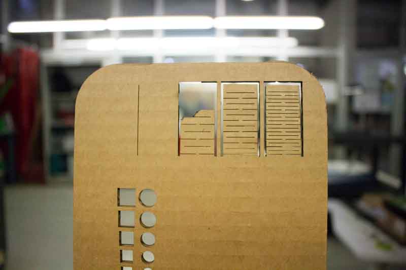
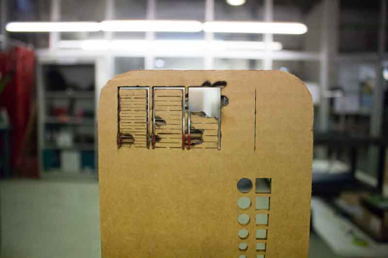
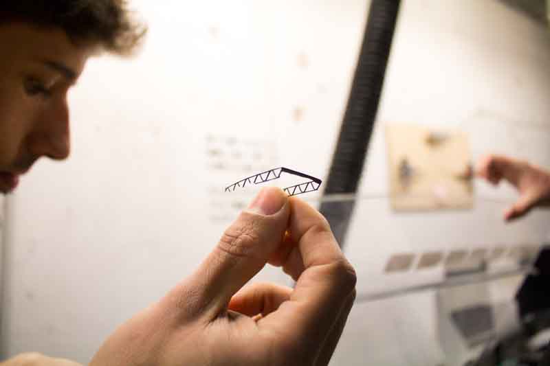
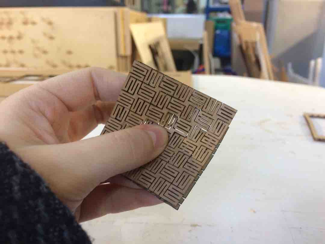
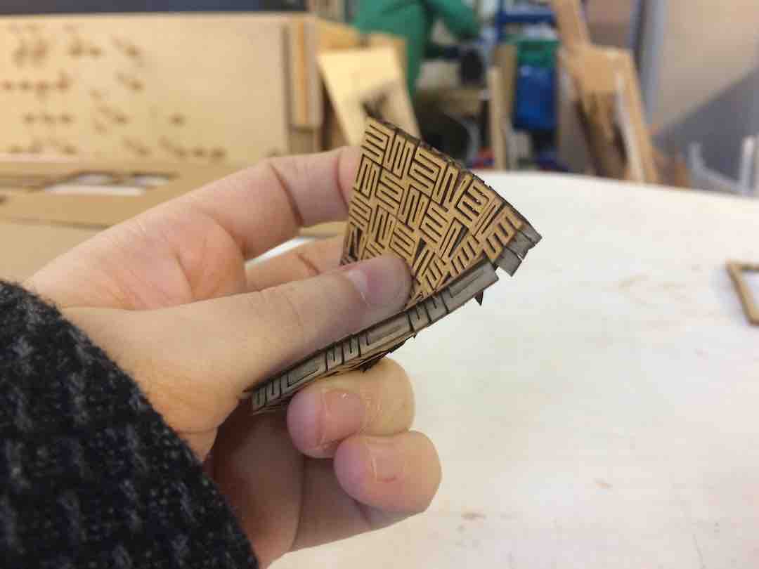
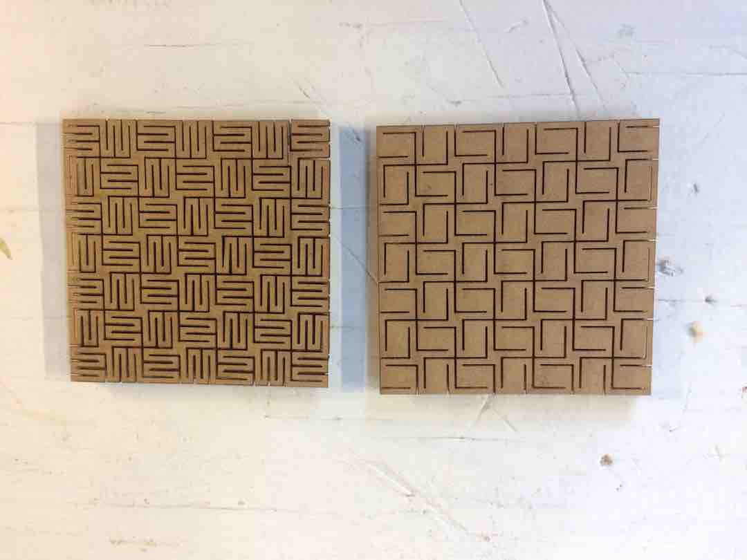
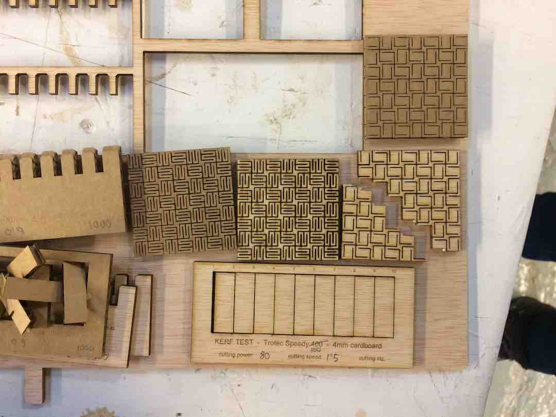
We also did some tests for malleable cardboard cut pieces with various degrees of success.

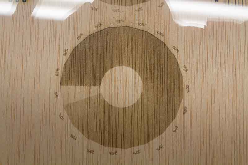
The kerf test on wood came out at 0.11mm for a setting of Power: 80; Speed: 1.50; Frequency: 1000Hz.
The press fit test failed, because we forgot to change the measurements to those of the plywood, so obviously the were huge gaps in all the crevices.
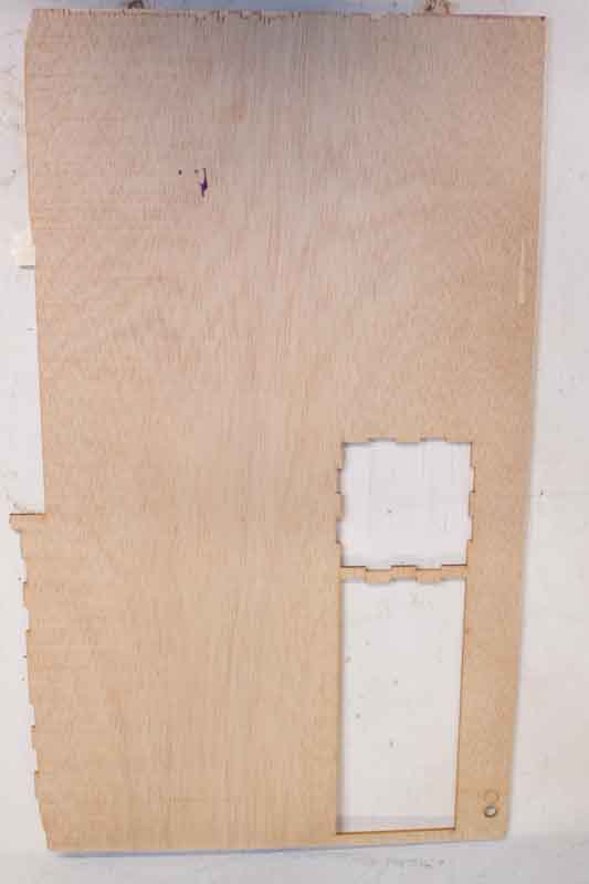
We did the same malleable tests on plywood. One of them worked out really well.


The second one broke when pressed.
Day 8
I gave up on the idea of the stool. It clearly is beyond my FreeCad knowledge (which isn’t much to begin with) and I should go with the Platonic Solid press-fit project.
Working out the parametric tools in FreeCad isn’t as simple as I first thought. Here they work as constraints, for instance you can lock a line to be parallel to another or vertical or horizontal, etc.

Day 10
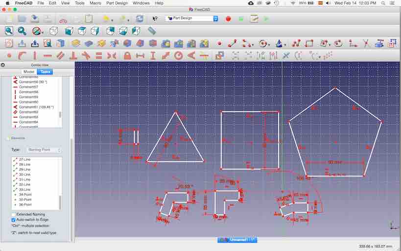
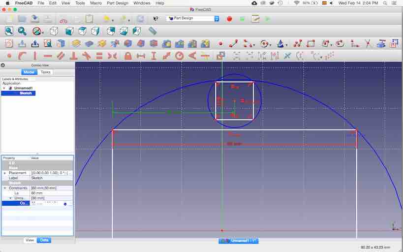
All my attempts to work with FreeCad have proven unsuccessful. After many hours I could only manage to do these shapes, with the correct dimensions but then I couldn’t work out the actual reference parametrics.
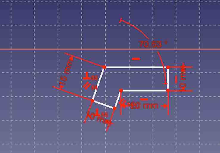
I was mostly successful with pieces like these, but when I wanted to pair up certain dimensions between objects and relate them to each other it was a complete failure.
Even as I named an object, it wouldn’t recognise the name or take the reference to it or form new constraints based on the objects dimensions.
I could have very easily done the design directly in Rhino, laser cut it and actually have something to show for today, but since the exercise was to work the parametric aspect of the press-fit I decided to keep trying and catch up in the next few days. I might even borrow a computer to work on a different program.
I decided to cut it, without the parametric part of the design just yet, but I’ll figure it out eventually.
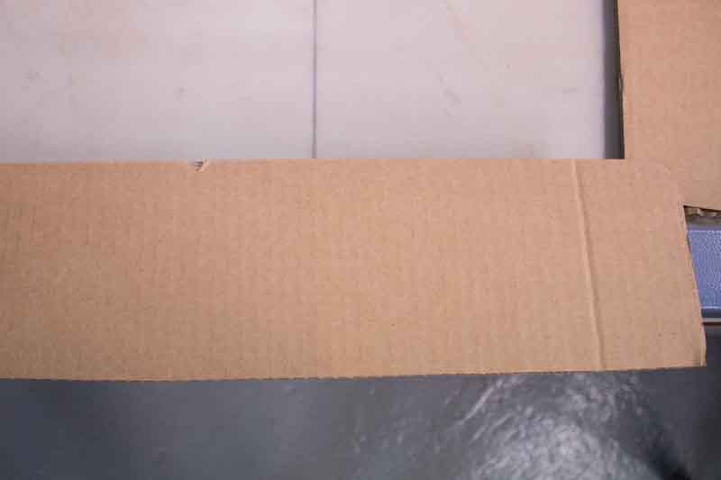
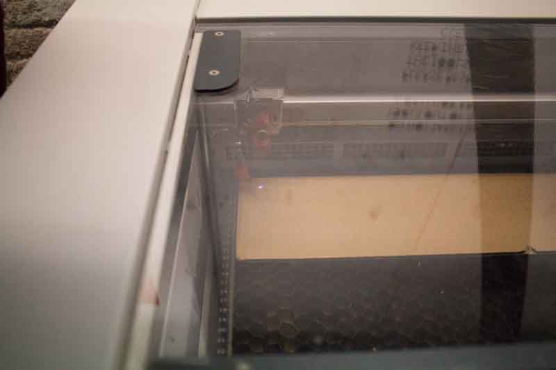
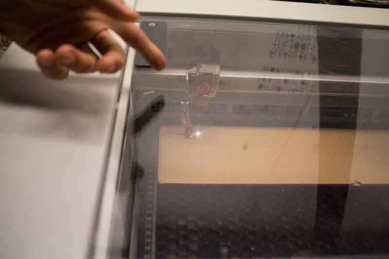
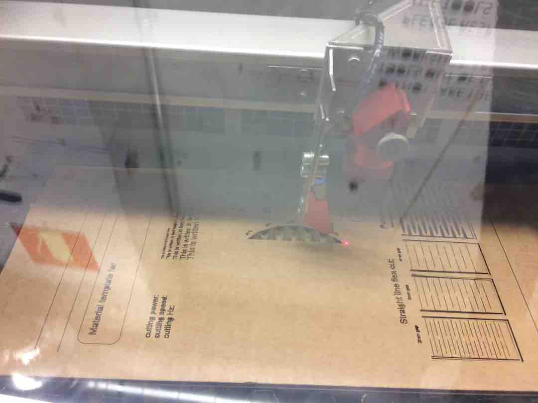
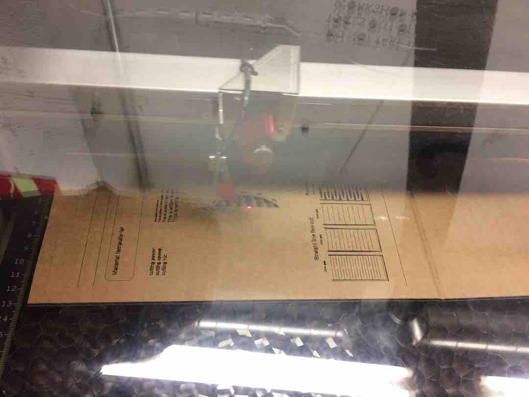
For the laser cut machine I used the TROTEC Medium format Laser Cutter (Trotec Speedy 400) that has has 1000mmx600mm dimmensions to cut 4mm cardboard as a material.
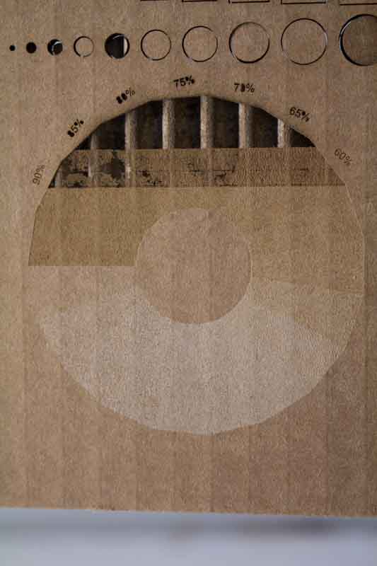
Focusing the z-axis, is an important step. I prepared a brief test for assessing the Power/speed trade-off of the material.
This machine in particular has to be used with a Speed < 1, since it has a y-axisproblem, frequency at approximately 1000Hz. There shouldn’t be flames coming out of the material (obviously) while cutting. The recommendation is to keep as low as possible the power, in order to reduce the kerf.
After this test, for cardboard 4mm, the final parameters found were:
CUT: Power = 25% power / Speed = 0.9 / Frequency = 1000Hz
ENGRAVE: Power = 7% power / Speed = 0.5 / Frequency = 1000Hz

VINYL CUTTER
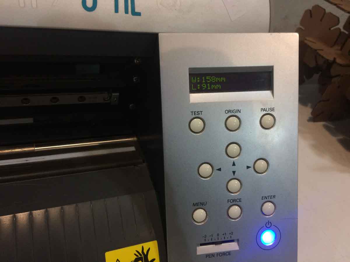
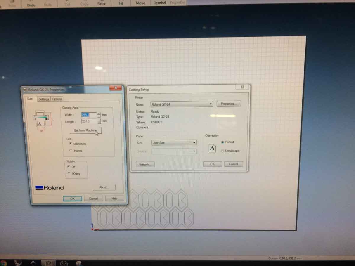
I worked with the Vinyl cutter today, which proved to be a thousand times simpler than the laser cutter.
The machine runs in CutStudio and it’s really easy to set up. I did a simple module in Illustrator, which can be imported to CutStudio, and repeated it a few times for fun.
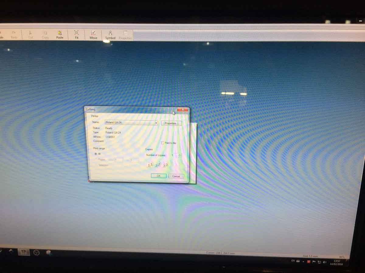
It worked out perfectly the first time around, there was no need to change anything.
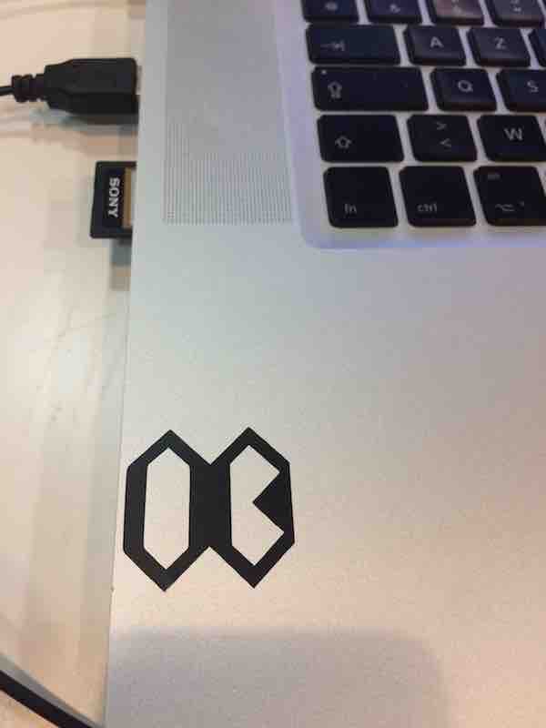
Even at this scale, which was almost 30mm in height and 40mm wide, when I looked closely, it wasn’t terribly precise. I was expecting a cleaner cut but the results aren’t too horrible.
I did a second run in smaller scale to see what size and at what precision the machine would work.

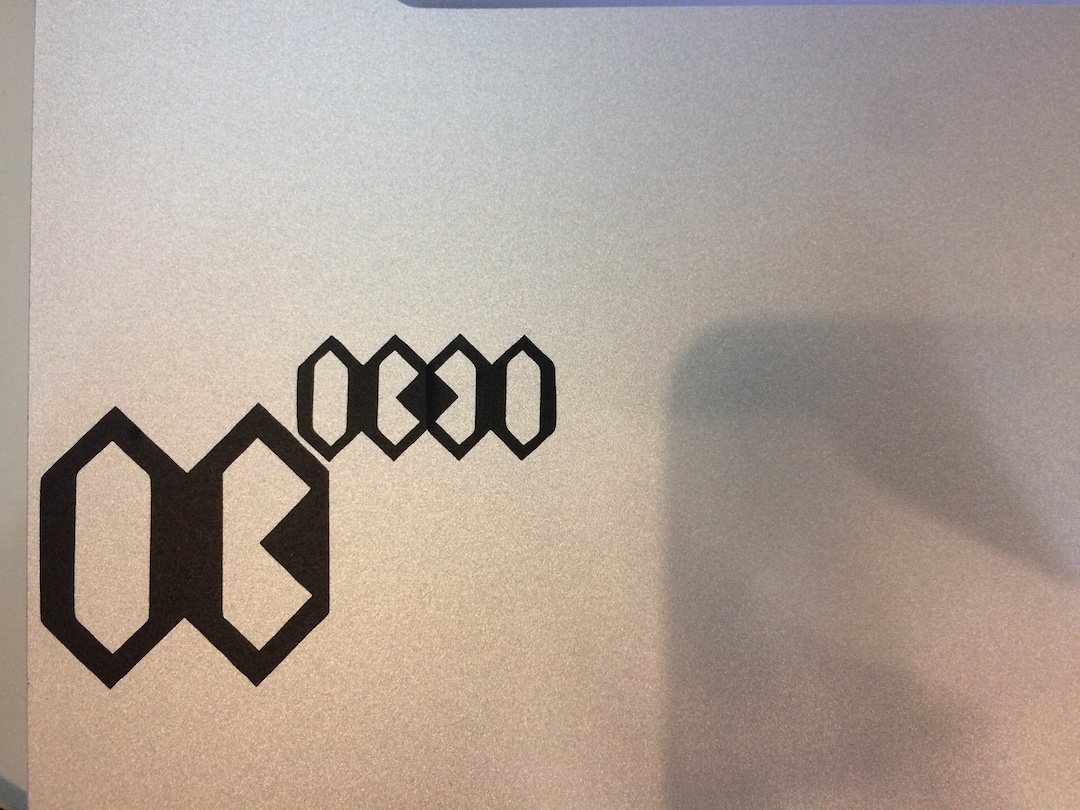
I scaled it down by half and it worked with about the same precision as the first one. The match point between modules is somewhat muddy but with enough care they match as intended.
You can download the files for these here and here.
Day 35
I managed to fix the problem with the operating system and attempted to do the design with Rhino and Grasshopper for Mac. The RhinoWIP comes with Grasshopper so there is no need to download and install separately.
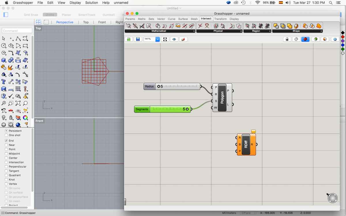
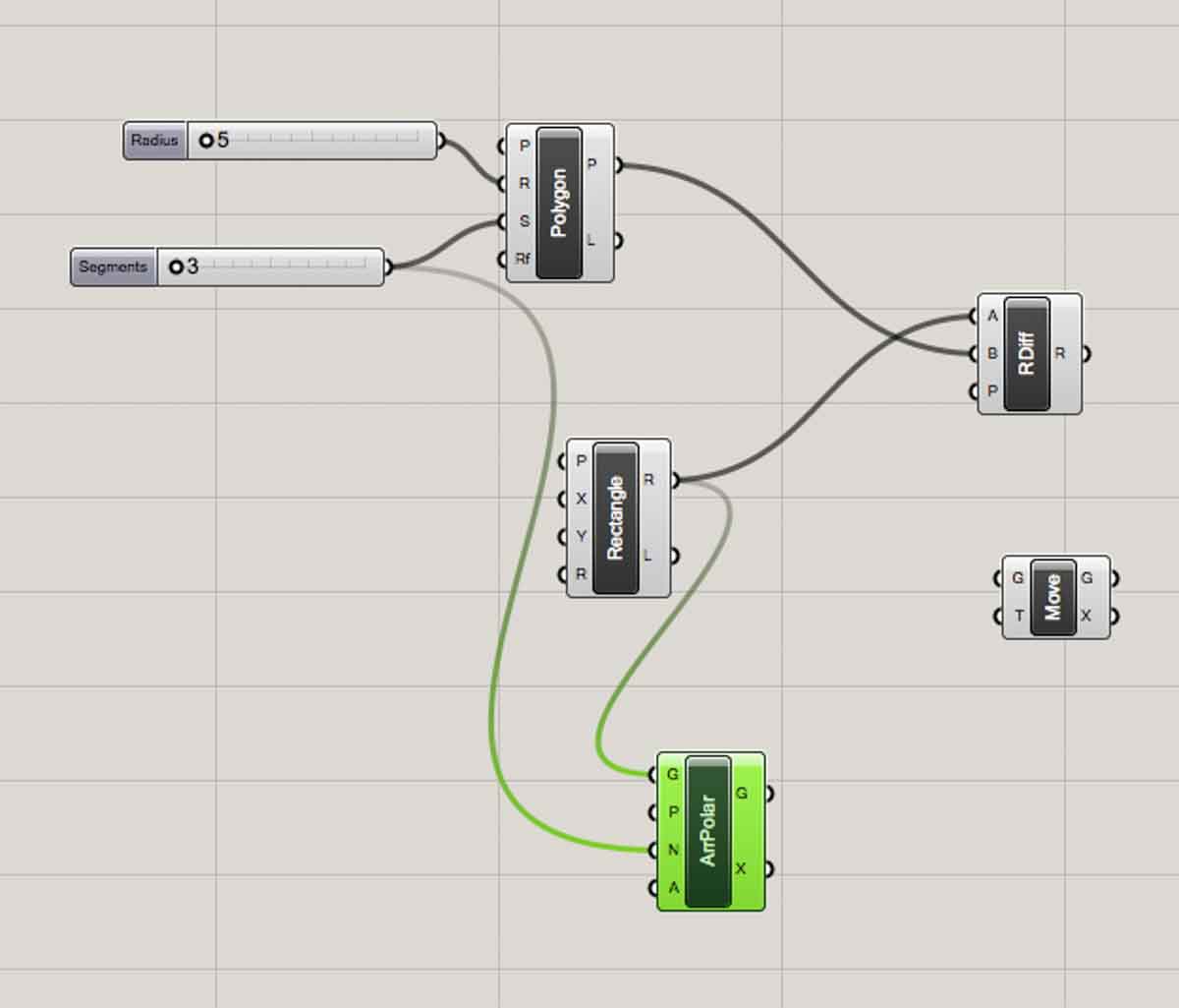
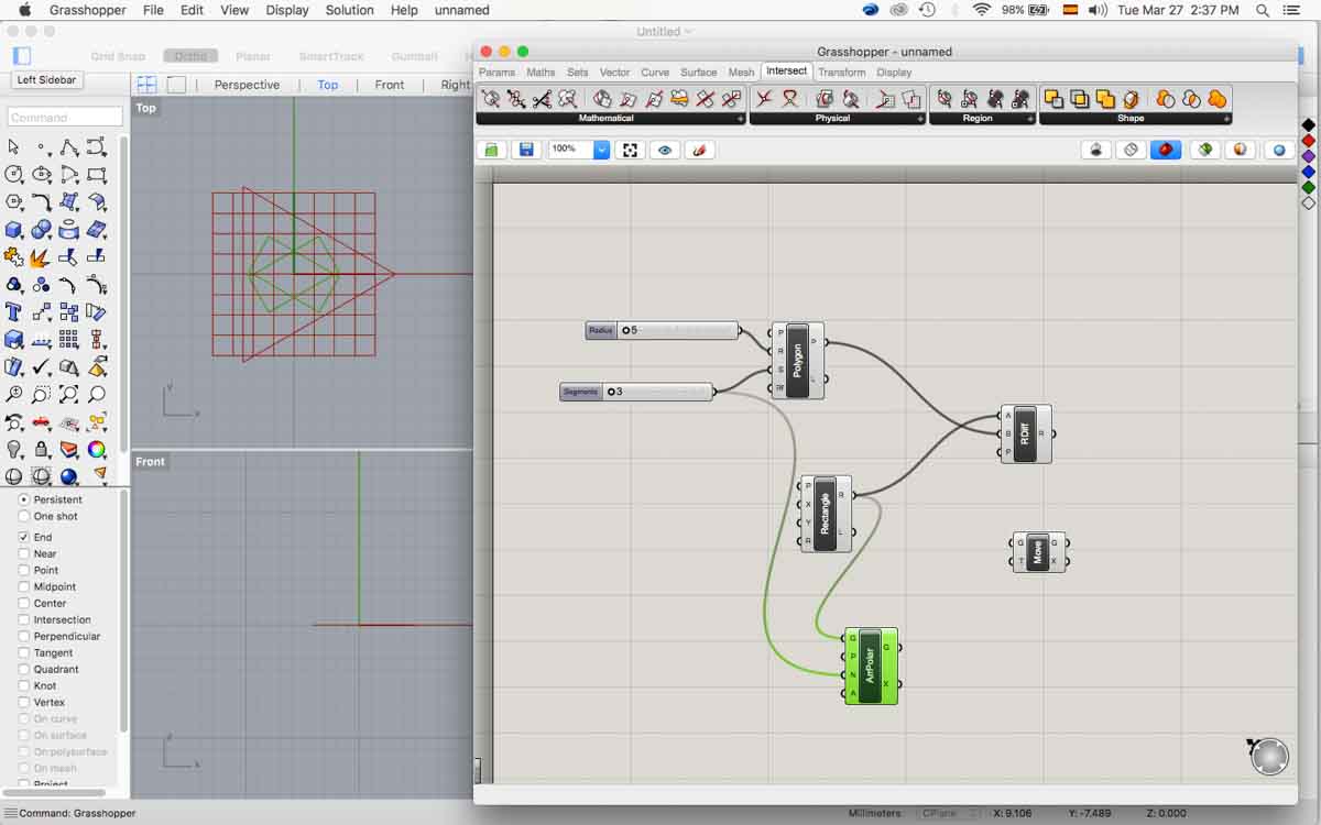
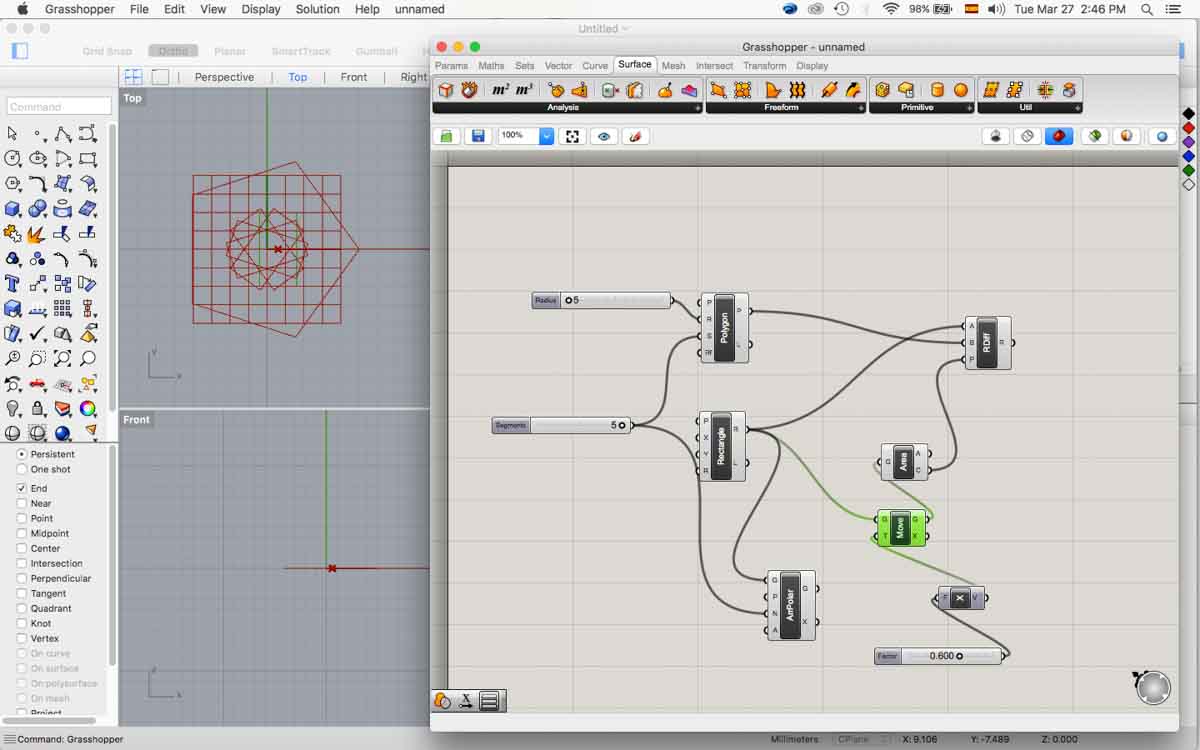
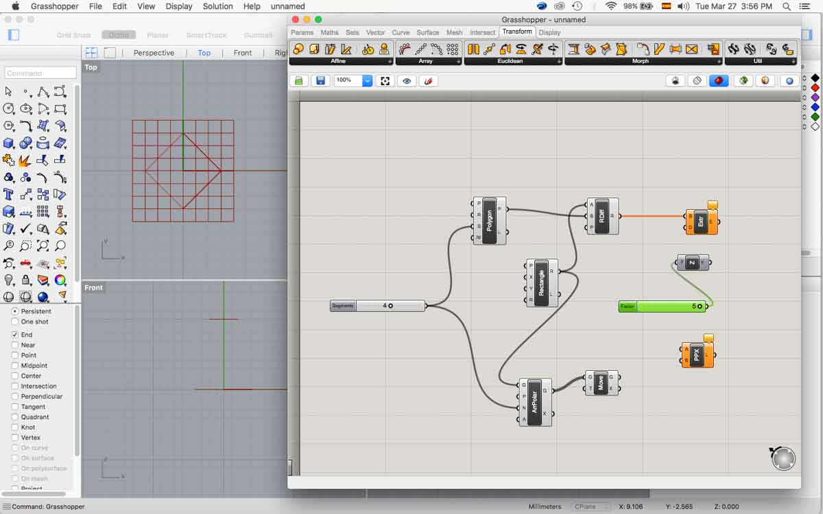
The files for these explorations are here and here .
I also worked to how to name name constraints properly in FreeCad.
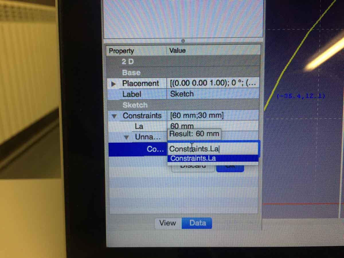 ...
...
Other Pressfit designs can be found in Machine building week and Final final project.