WEEK 5: ELECTRONICS PRODUCTION
Day 1
Class:
Frankly most of the class went over my head. The only thing that actually stuck was that the two methods to make circuits in small scale are by milling them and by using the vinyl cutter with copper paper.
There is a group assignment to characterise milling the machine, take everything apart, get a new end mill, etc. Test patterns and circles.
Also to make a programer (?) whatever that means.
Once again, I’m lost. Every time I think I’m catching up the new week’s assignment is given out and I find I’m not sure where to start.
Day 2
I’m happy to see that the basics of electronics are going to be addressed. There’s a list of suggested books, which I appreciate immensely.
Out the whole talk I only really understood that we’re building a Programmer. Those are used to upload code that “translates” instructions in different computer languages. At least that’s what I understood. After this we would be able to buy an Arduino ONE and program it. I now also know what an Arduino and a Raspberry Pi are, which apparently are two version of the “same thing” but is still a vast improvement from week one.
Also, apparently C and C++ are programming languages... whatever that means.
Day 3
Group Assignment:
Our group consisted of:
Marta Bocos
Ilias Bartolini
Óscar González Fernández
Joris Navarro
André Pulcino
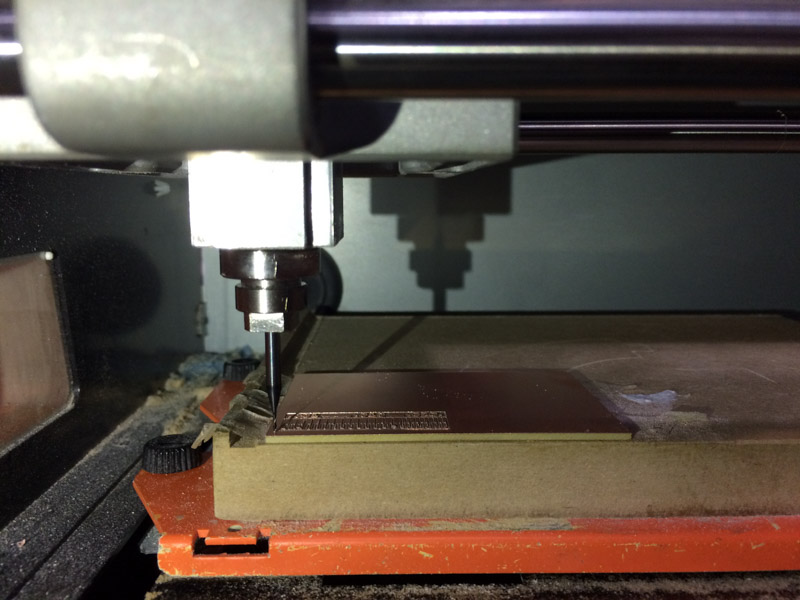
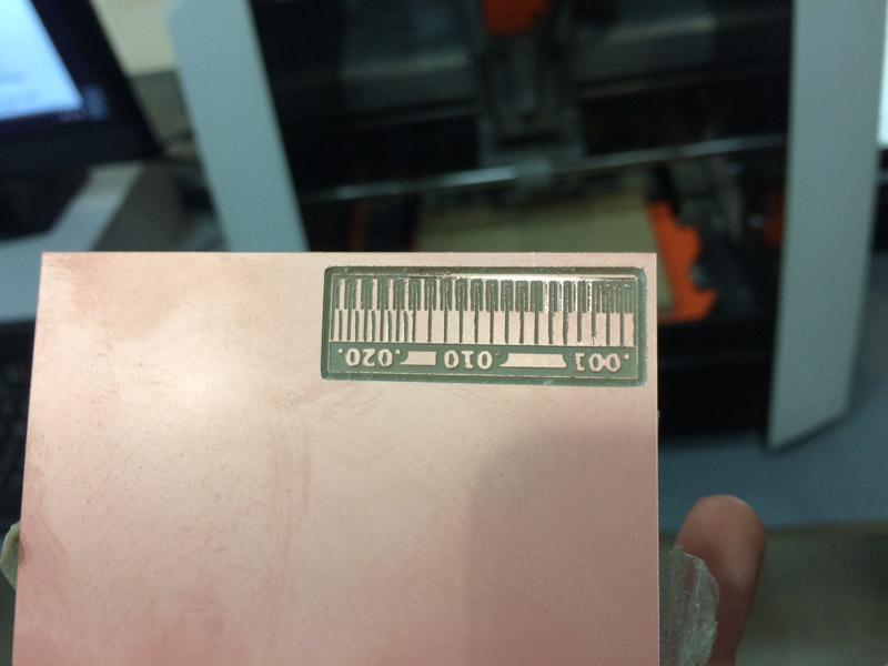
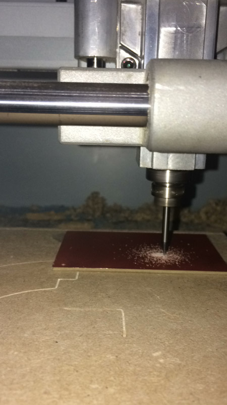
We’re using a SRM-20 Roland Machine. In this process we will be milling a FR1 (phenolic paper) board using the CNC milling machine.
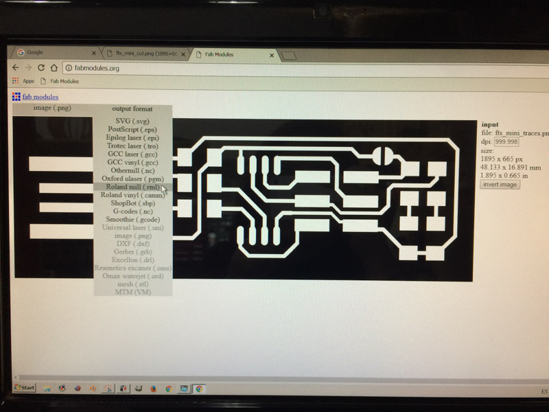
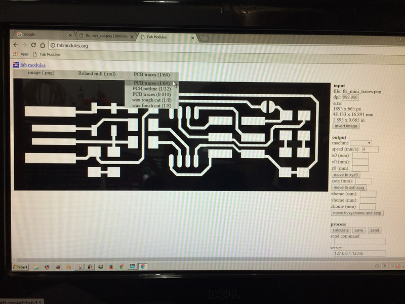
The first step was to make a conversion of our traces design from .PNG, which is an image file (that was provided for us) to .RML files, which are the ones supported by the Roland SRM-20 mill.
The traces png file to be machined with a 1/64” tool:
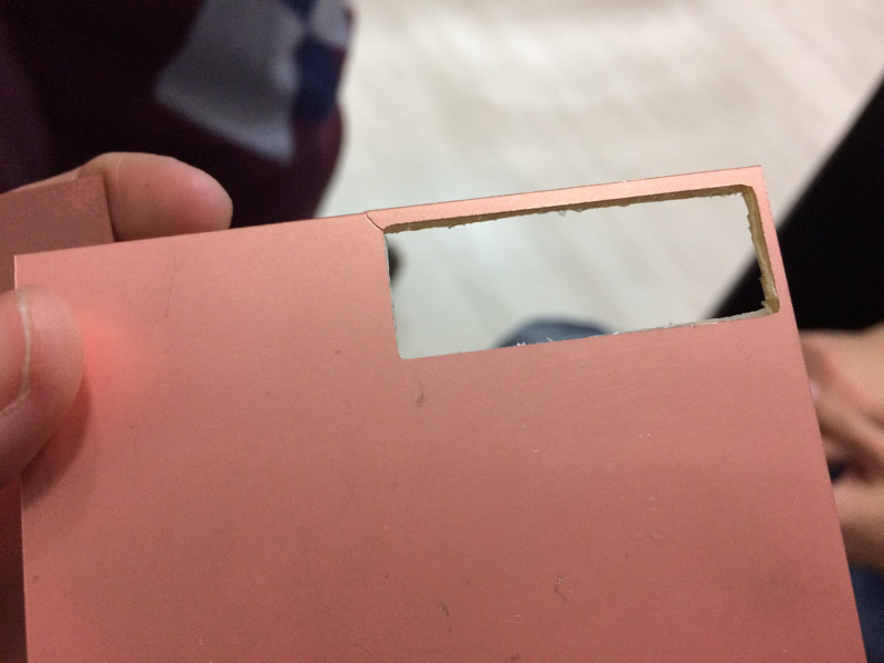
To cut the board out of the copper layer, we will use a 1/32” tool on the following profile:

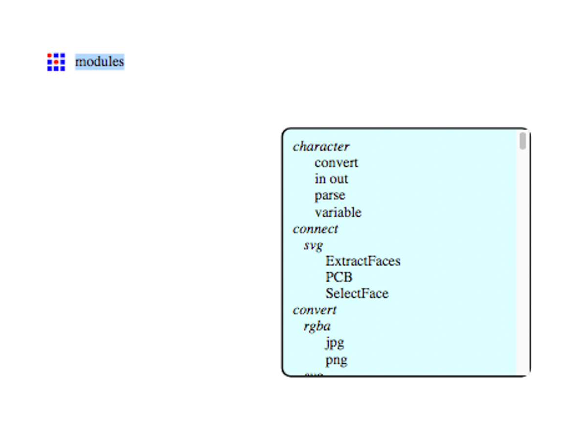
For that purpose, the png files will be passed through the FabModules. Since it detects changes between BLACK and WHITE in the png files and generate a path in it for the machinning process, you need to be aware of which one you want to mill.
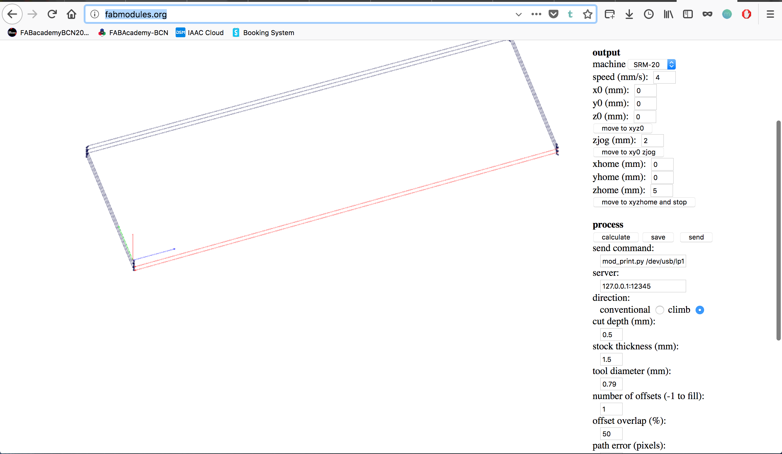
The settings selected for the PCB traces are:
- Upload image as *.png
- Output file as Roland mill (*.rml)
- PCB traces (1/64)
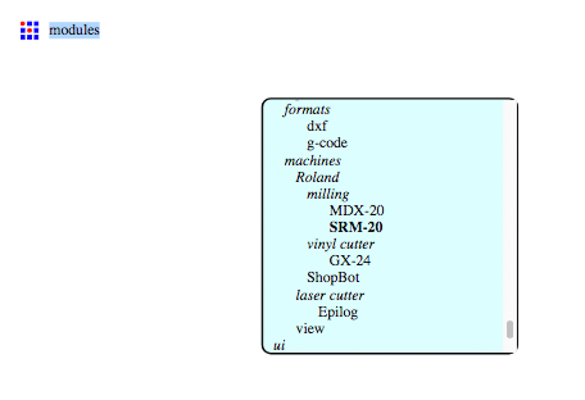
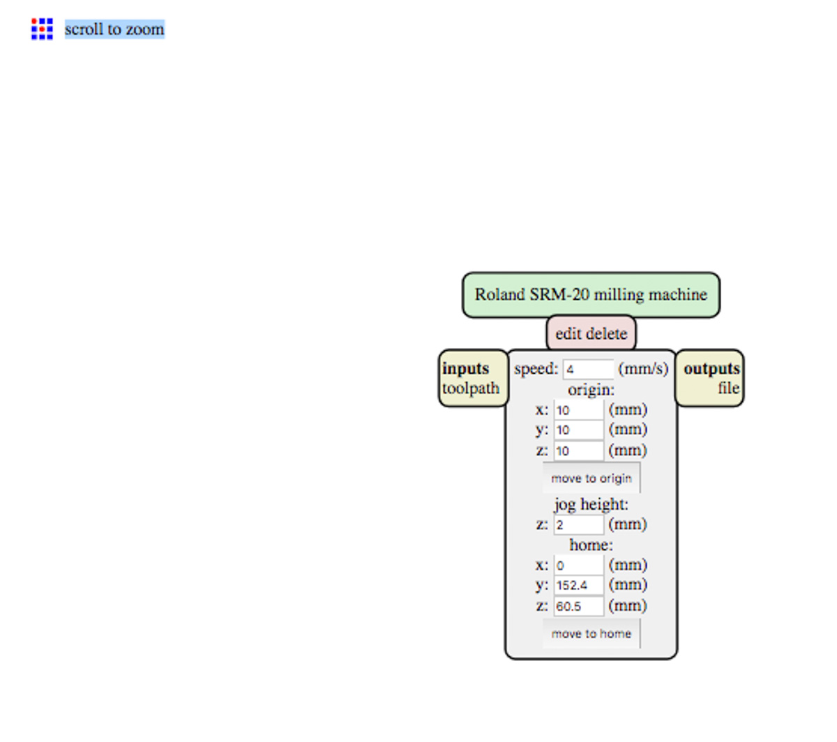
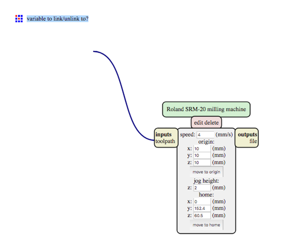
- Machine: SRM-20
- Origin: X0, Y0 and Z0 are set to 0mm, in order to keep the same origin as the locally defined in the machine
- ZJog is set to 2mm, meaning that the machine will lift the tool 2mm while not cutting
- Xhome, Yhome, Zhome are set to 0mm, 0mm and 5mm. The latter being the most important, since it is the value at which the tool will be positioned once the job is finished. If this value it’s zero, it will scratch the whole copper surface, very likely breaking the tool
- Cut depth: 0.1mm
- Offset: 4. It’s the number of offsets that the program will calculate out of the BLACK-WHITE transitions. A number of -1 will remove all the copper.
- Offset-overlap: 50%, relative to the tools diameter (1/64” in this case)
- The settings selected for the PCB outline (only detailing the ones that are different):
- Cut Depth: 0.5mm
- Stock thickness: 1.5mm
- Number of offsets: 1
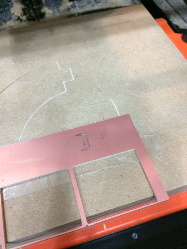
Something went wrong when the generated traces came out. Apparently, this was because the below line is not properly detected. What we did was flip the image upside down in order to have the cutting traces in the lower side of the cut.
Day 5
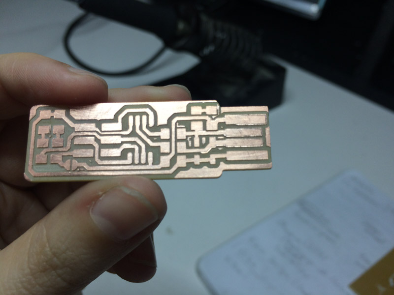
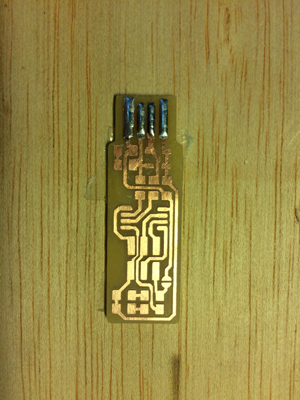
For my personal assignment I used Brian’s FabTinyISP board , provided in the FabLab page to make my programer.
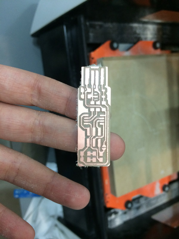
The tracing was also done with FabModules, as I found it to be much more simple than it’s newest version Mods:.
While very useful and not dissimilar to Grasshopper, it simply demands a specificity in knowledge I don’t fully possess at the moment.
The milling was done with the same machine and characteristics of the group assignment and it went without a hitch.
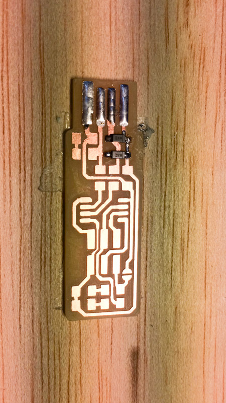
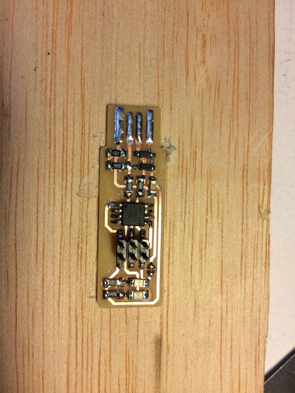
I looked for the listed parts and soldered them to the board.
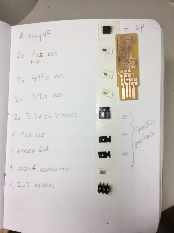 1x ATtiny45 or ATtiny85
2x 1kΩ resistors
2x 499Ω resistors
2x 49Ω resistors
2x 3.3v zener diodes
1x red LED
1x green LED
1x 100nF capacitor
1x 2x3 pin header
1x ATtiny45 or ATtiny85
2x 1kΩ resistors
2x 499Ω resistors
2x 49Ω resistors
2x 3.3v zener diodes
1x red LED
1x green LED
1x 100nF capacitor
1x 2x3 pin header
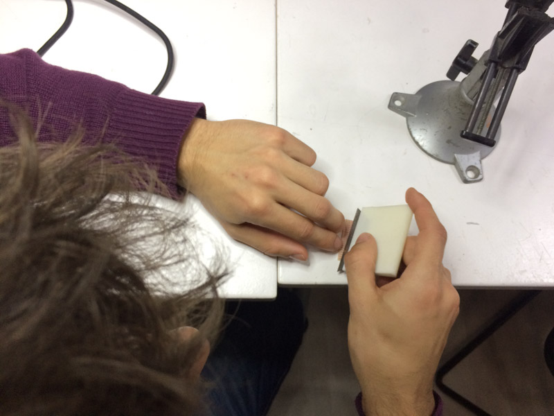
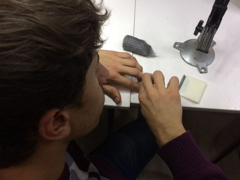
It’s important to note that the copper covering needs to be cleaned with alcohol before attempting to solder anything to it or the connectivity might be compromised by skin oils or such, isolating the copper line.
The soldering process was somewhat difficult, most of the connections could look better as the solder was too hot. Lucky, none of the components were burnt and after checking, all of the connections were made properly.
Day 10
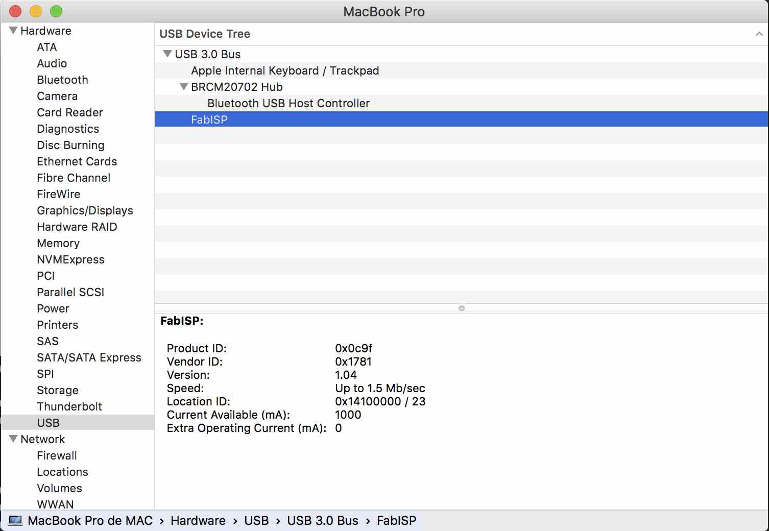
For the programing process, I followed the instructions provided in Brian’s page step by step.
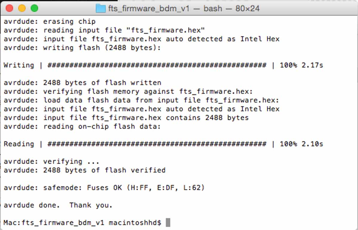
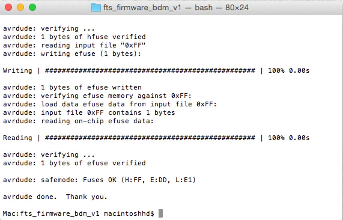
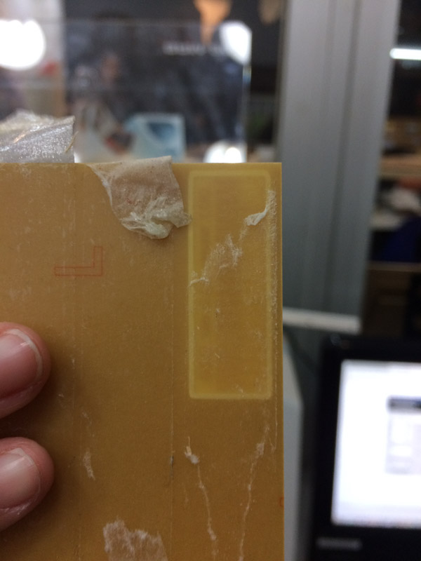
I had a lot of trouble getting my computer to read the programer, but apparently this is a very common problem with this programer design, since there’s almost no contact between the board and the computer USB port.
However, after I stuck a layer of thin vinyl to the back of it, it works fine.