Group Task
Computer-Controlled Cutting
Setup
Our FabLab has a Epilog Zing 24 Laser with a work area of maximum 610 mm by 305mm(more information here).
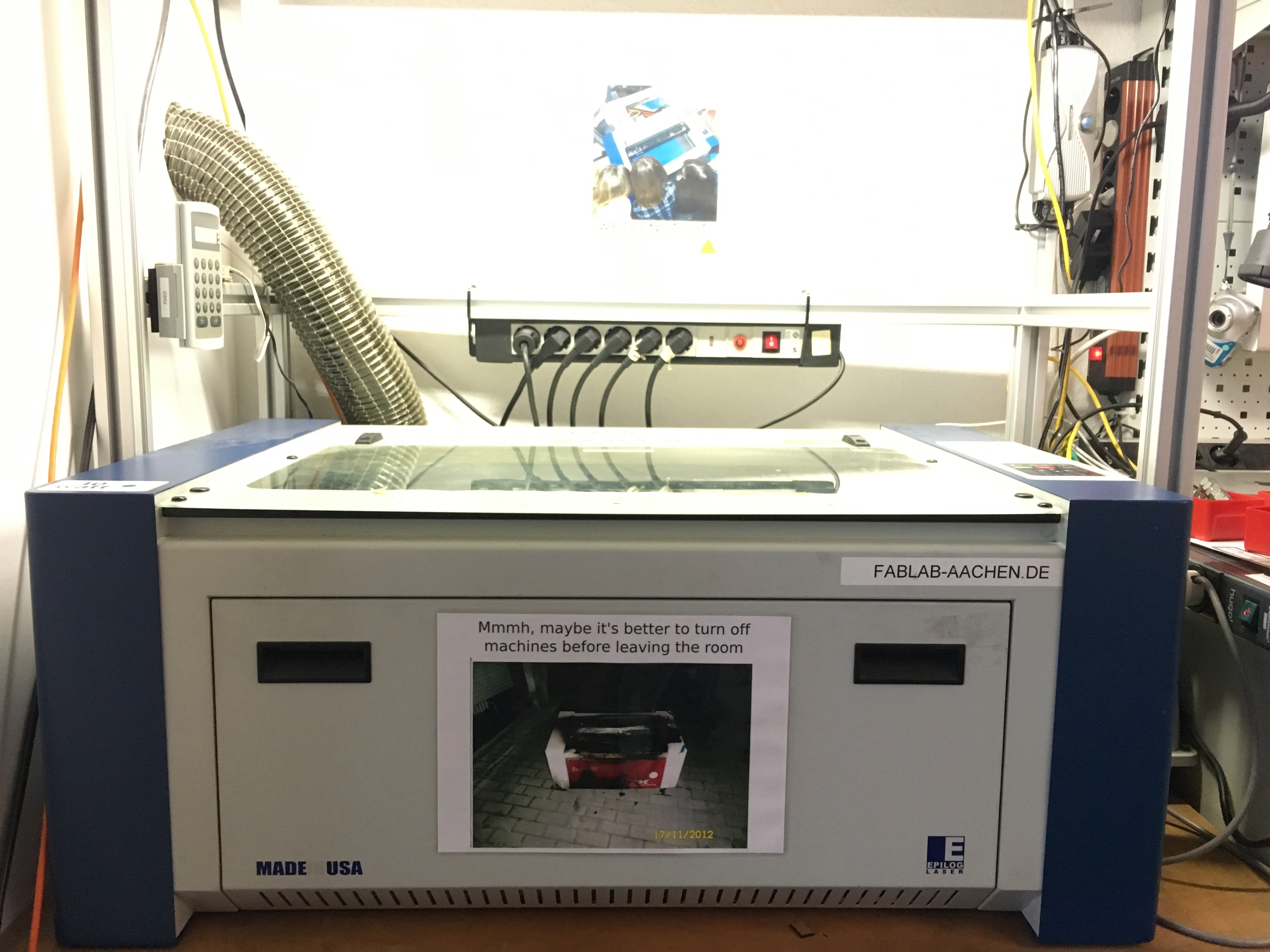
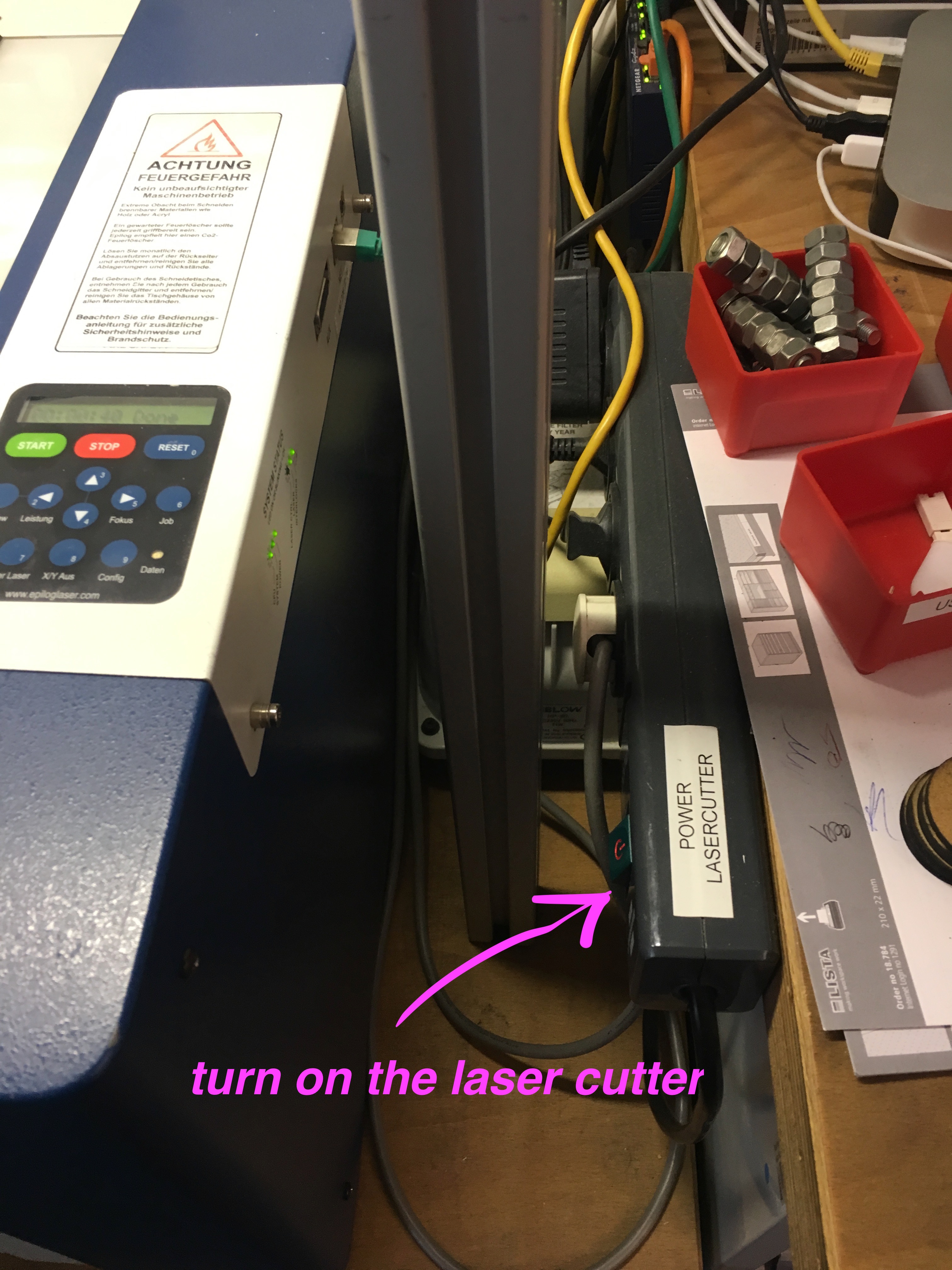
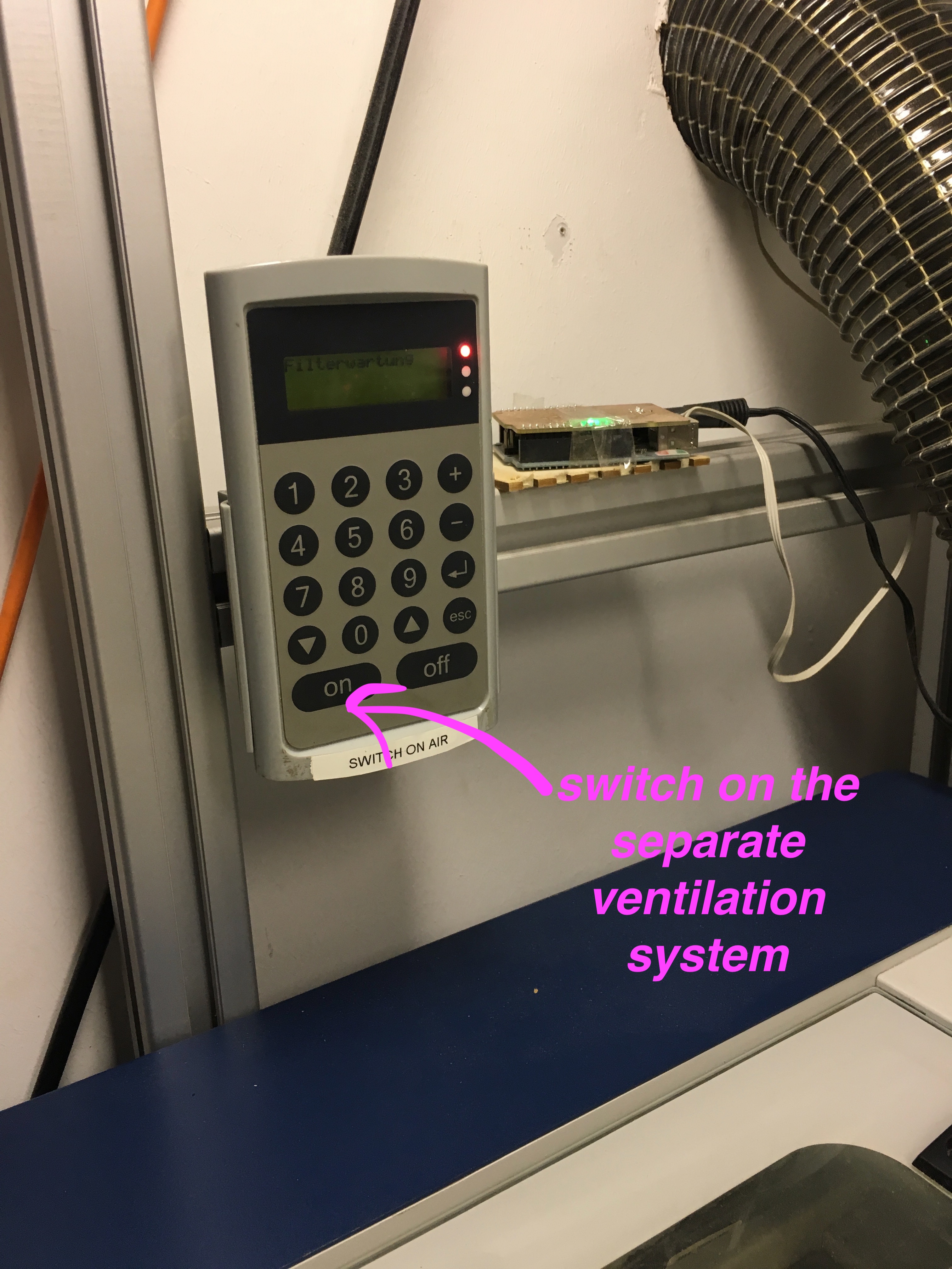
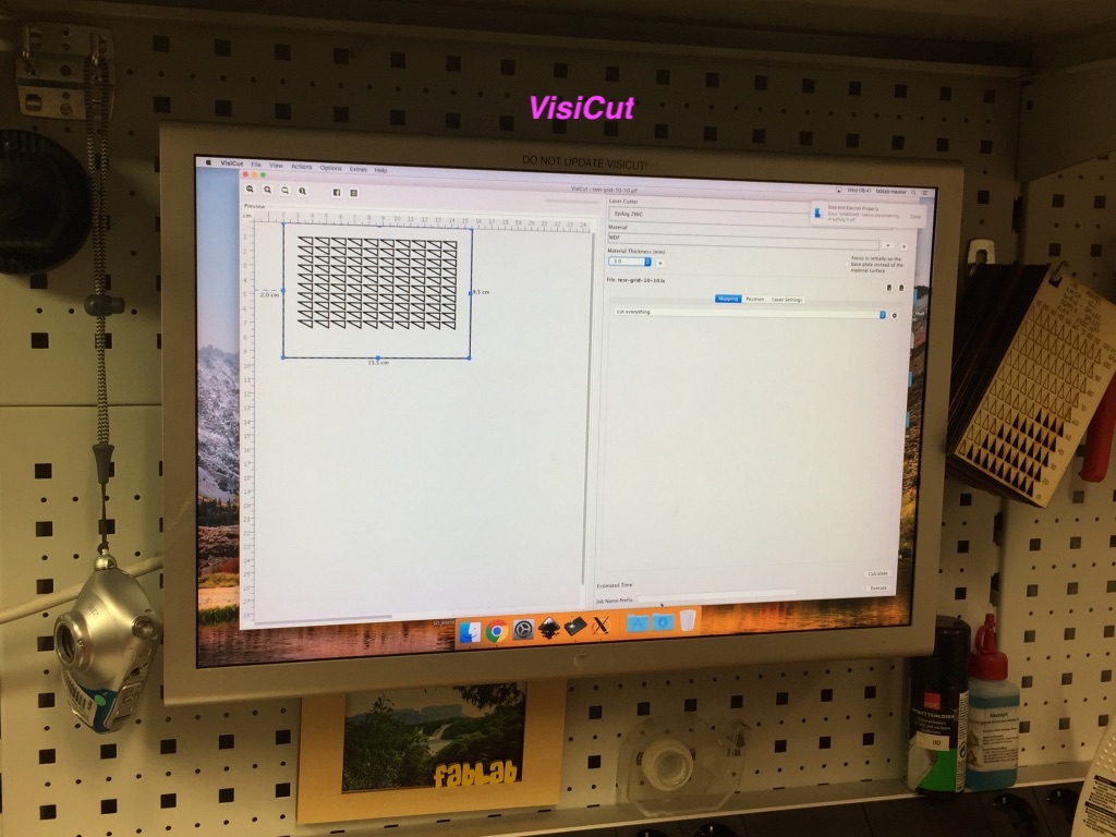
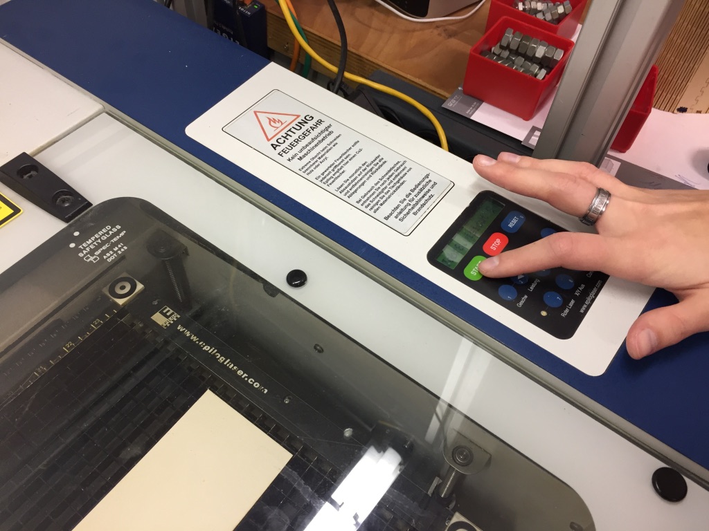
Our local tutor Marcel gave us an introduction on how to operate the laser cutter. Turns out it is not as difficult as we imagined. In order to start working with it, we have to first turn on the laser cutter, and then switch on the separate ventilation system. The tool we used to interact with Laser Cut was implemented at the Media Computing Group and is called VisiCut . It is installed on the desktop right next to the machine.
General Instructions
Thanks to the Aachen FabAcademy 2017 for writing such a good instruction:
- Put the chosen material on the laser bed.
- Select a material, some options we have available are: plexiglass (2mm to 6mm), finnpappe (1mm to 3mm), MDF (3mm to 5mm).
- Point the focus on the laser cutter itself( this depends on the material chosen):
- Put the chosen material on the laser bed.
- Click the focus button on the laser cutter menu.
- This will move the laser cutter "arm" a bit forward, so we can use the focus "pin" to set the correct value.
- Use the up/down arrow keys on the laser cutter menu to set the focus so the pin just scratches the surface.
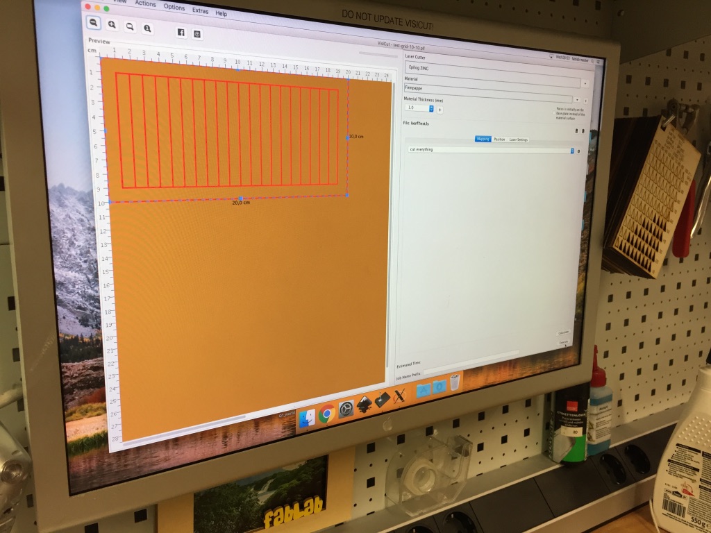
- Prepare the laser job in VisiCut.
- Any model you make should be exported into the svg file format and put on a USB stick.
- Plug the USB stick into the laser cutter desktop, and open the svg file of the model you want to cut in VisiCut.
- Position it (and possibly scale it) on the canvas shown on the left hand side of the interface.
- On the right hand side of the interface select your material from the dropdown menu, and also set the chosen thickness in the box below.
- On the lower right hand side a tabbed menu is shown, in the first tab "mapping" you can select which laser cut function needed. The options are: cutting, marking, engraving and 3d engraving.
- In another tab "position" you will be able to select a reference point on your model (center, upper left hand corner, etc.) and then position the model accordingly.
- The final tab "laser setting" will be discussed in the next sections.
- Sent the job to the machine.
- Wait patiently for the job to finish, always keeping an eye on it for safety reasons.
- Then wait another 5 minutes before opening it and taking the piece(s) out.
Kerf Testing
Theoretical
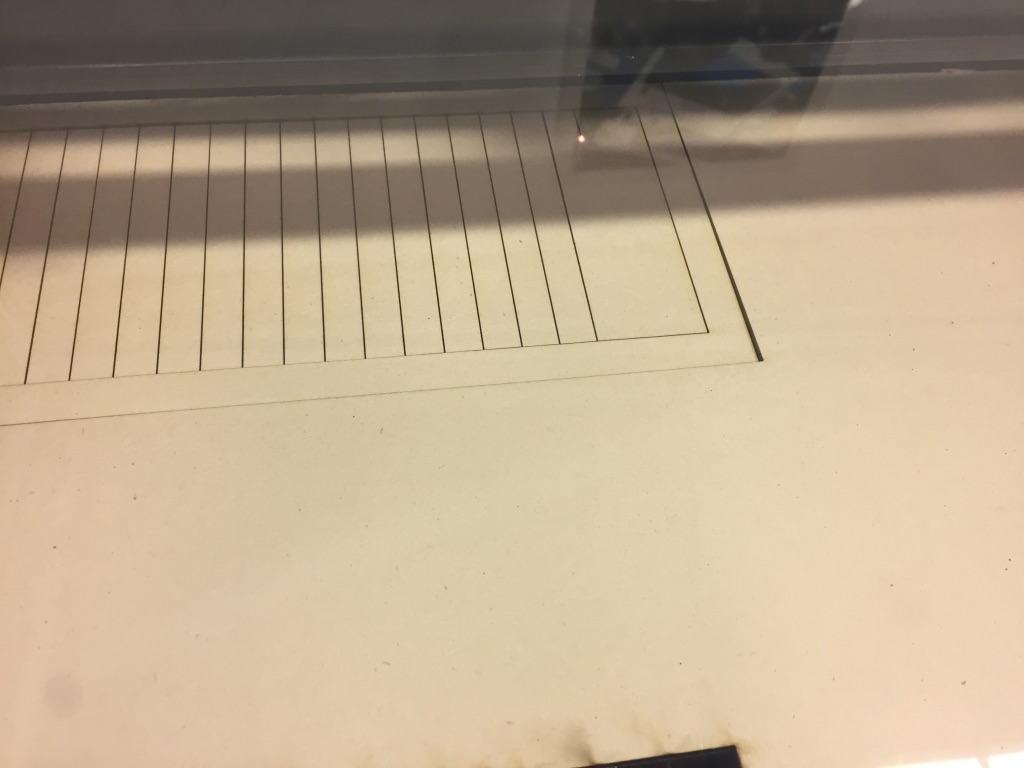
The laser burns away a portion of material when it cuts through. So, measuring kerf (width of a cut in woodworking) is an is important property in laser cutting. Kerf varies accroding to the materials. But, what is more, it also depends on the parameters in laser cutter(speed, power). As an inspiration we took that article. To measure a kerf, Matthias designed a long rectangle consists of n small pieces(also rectangles). With this design we were able to change n, but almost all the time n = 20.
-
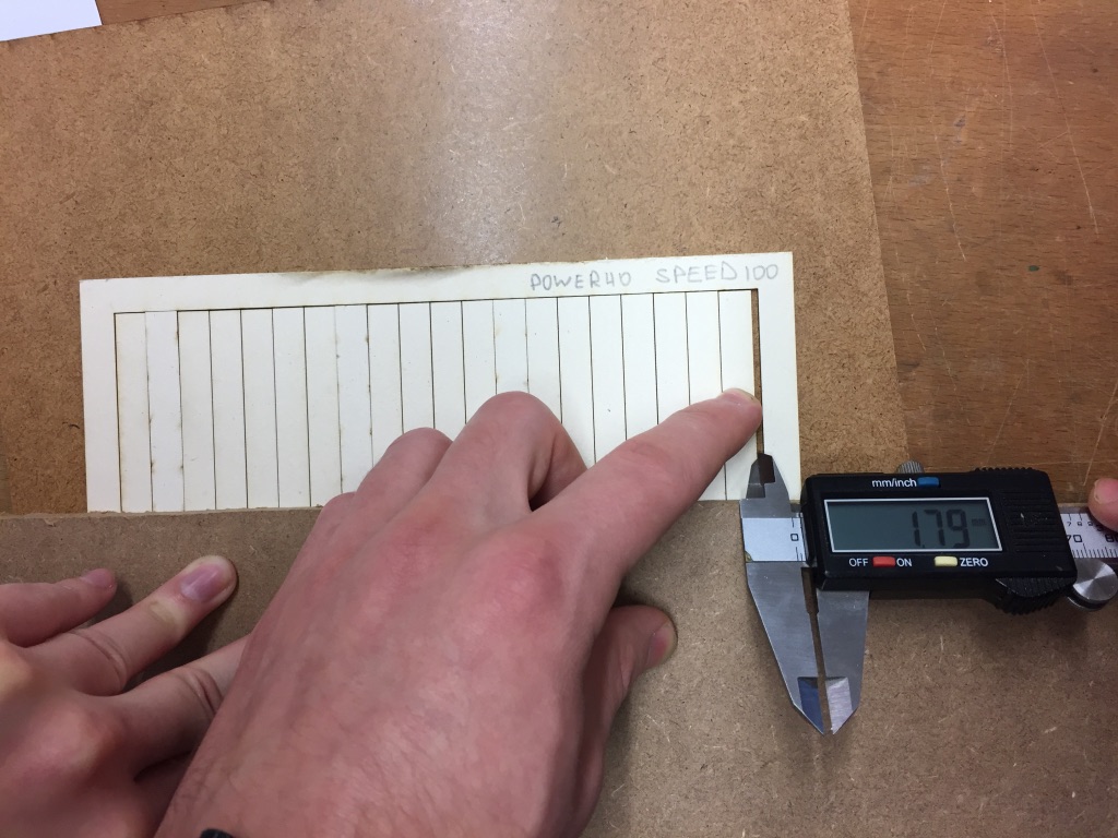
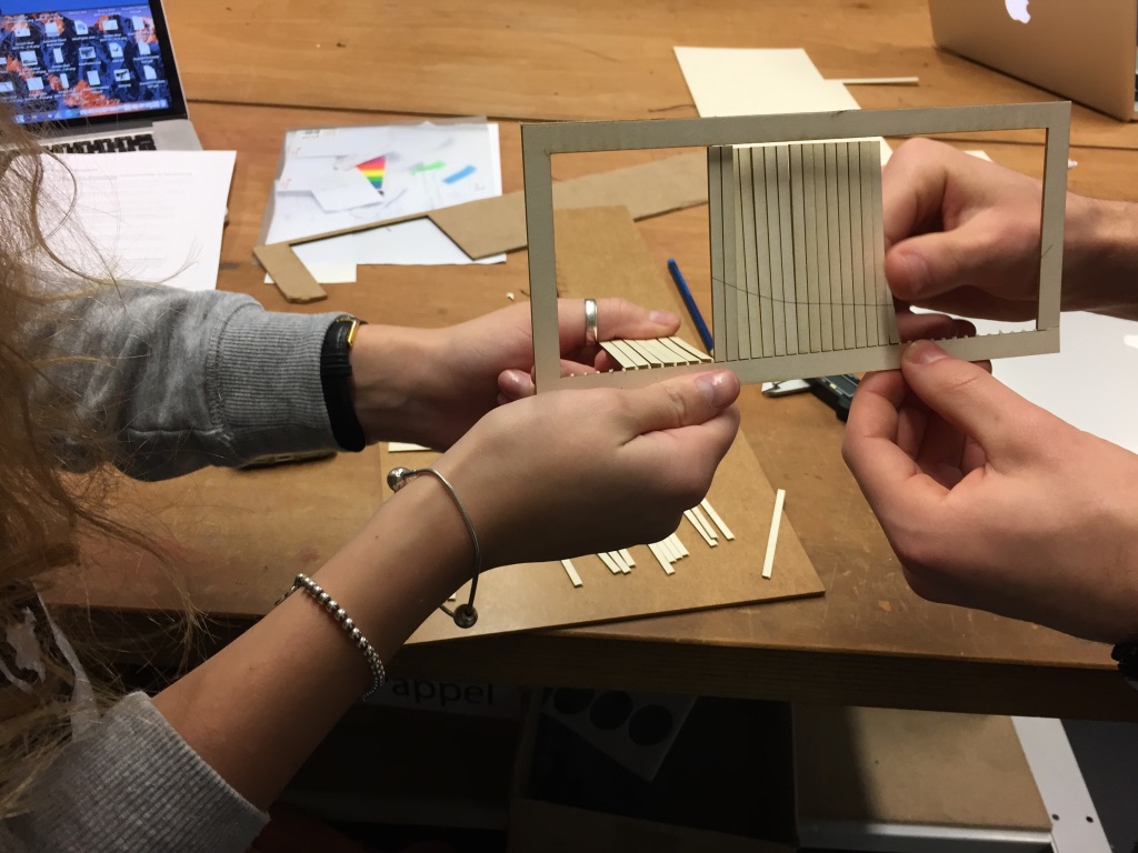
1. Our first kerf test was made with 1mm Finnpappe and cut n = 20 pieces. The speed was 40% and the power 100%. After cutting Svetlana and Matthias placed all pieces next to each other and pushed them together.
2. When pushing them together we used a sliding calliper to measure how many mm the kerf of the laser took away. Anke took pictures during the group assignemnt for our documentation.
4. For n = 40 when pushing the pieces together we needed the hands of all three of us. Matthias explained to Svetlana and Anke how to use the sliding calliper properly and Anke and Svetlana tested using it when measuring the kerf width.
-
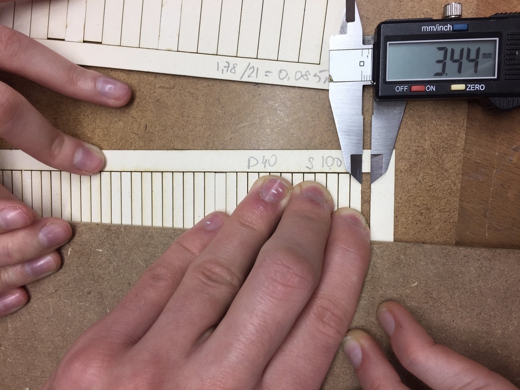
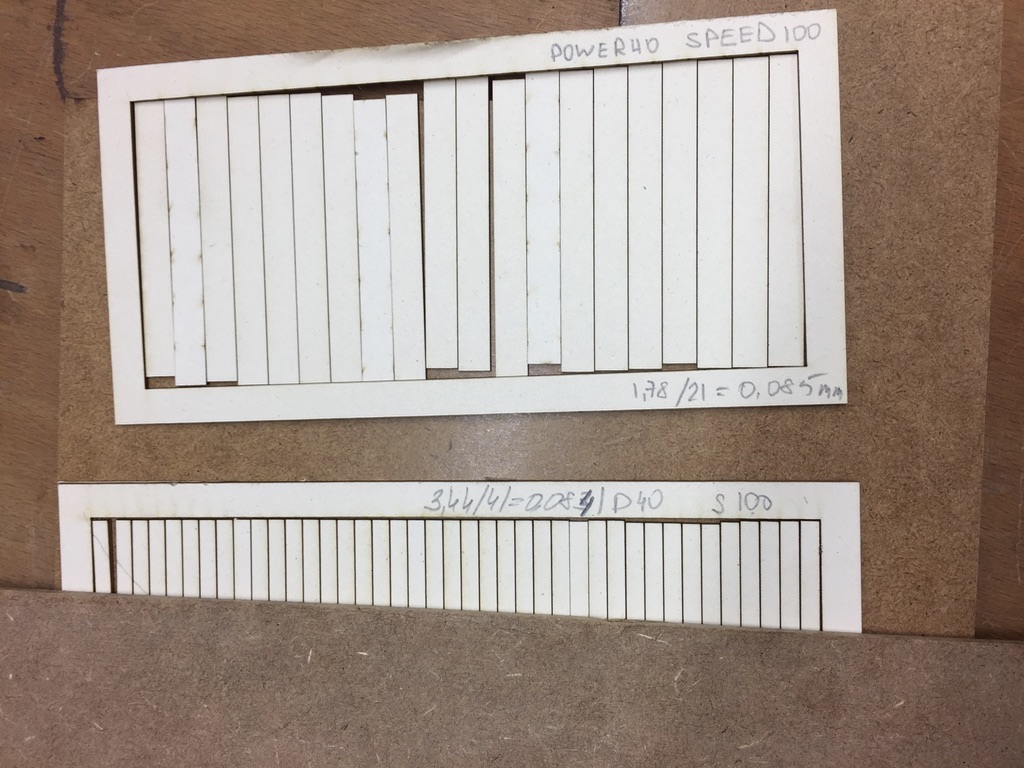
For the n = 20 pieces: 1.78mm/21 = 0.085mm
For the n = 40 pieces: 3.44mm/41 = 0.084mm
Comparing these two results we can estimate that for the material Finnpappe and 1mm teh kerf takes roughly 0.085mm away. Of Course, this value also depends on the speed and power parameters. And furthermore, also the thickness of the material and each Finnpappe itself influences the thickness of the kerf. Therefore, it is always important for an e.g. press-fit kit object to test the material in order to achieve a perfect result.
7. We repeated the pushing together and measuring step for the MDF.
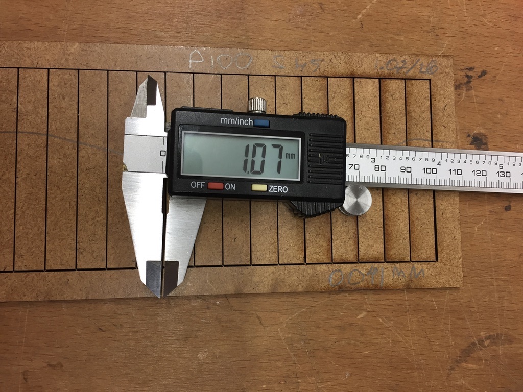
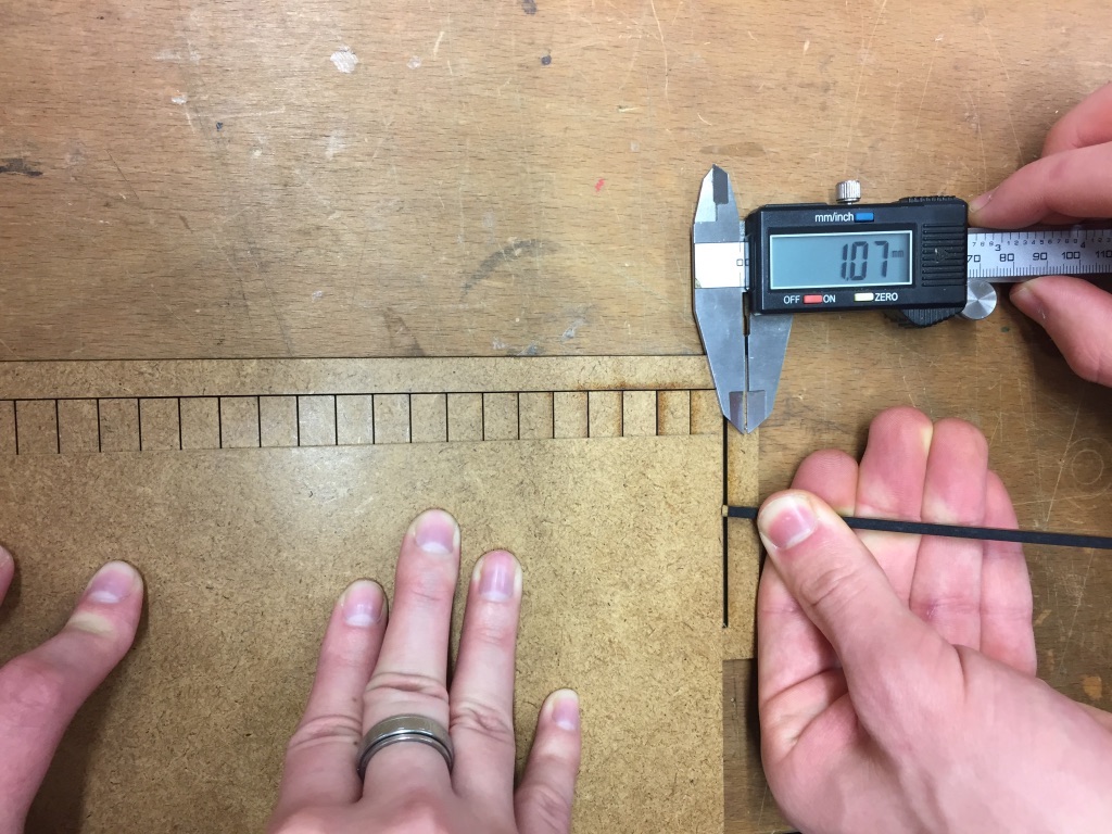
10. We repeated the pushing together and measuring step for the MDF. For this material we calculated a kerf width of 0.051mm (1.07mm/21 = 0.051mm).
Again the kerf is very dependent on the structure of the MDF you use and the paramaters.
11. As mentioned speed and power influence the kerf. We tested this influence with different combinations of speed and power. The documentation of these test you can see underneath the header 'Practical kerf test for press-fit kits'.
Download the file for the rectangle pattern here (LaserScript file for VisiCut).
Speed and Power Testing
The laser cutter can cut different materials of variable thickness.
Depending on material density, properties and thickness one has to adjust the cutting parameters,
in particular speed and power.
Our FabLab has already tested many materials and combinations. Their work is documented on their
website, but our task was it to experiment with those
parameters
and gather our own experiences.
Our test pattern features 100 small triangles arranged in a 10x10 grid.
Starting form the upper right corner power increases to left and speed increases to the bottom.
Both start at 10% and increase in 10% steps up to 100%
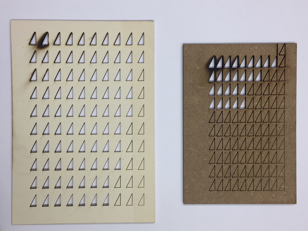
The left is 2mm finnpappe, the right 3mm MDF.
On both one can observe the burn marks at the upper-left corner resulting form maximum power at low speed.
To select good parameter values for future projects we recommend picking
a combination with a complete cut at highest speed in order to achieve low processing time.
In this case this would be 100% speed at 40% power for finnpappe and 40% speed at 60% power.
It is reasonable to select low power settings to reduce burn marks and kerf width.
Download the testing pattern here (LaserScript file for VisiCut, updated version including markings different orientation).
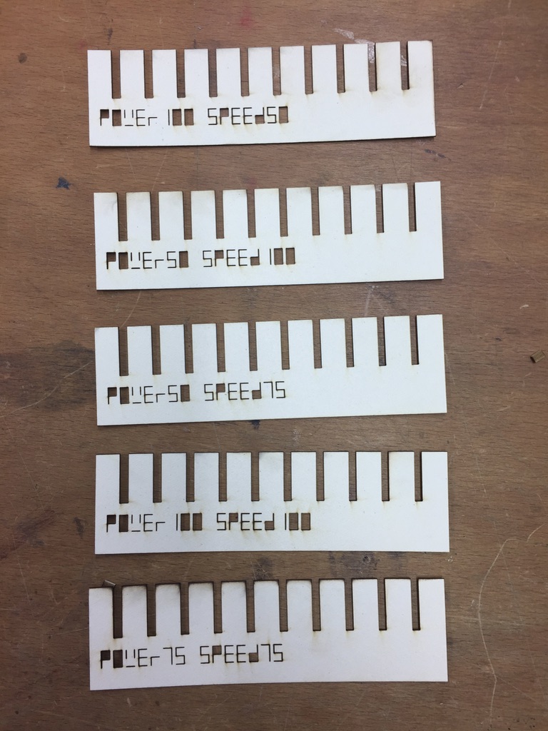
Practical kerf test for press-fit kits
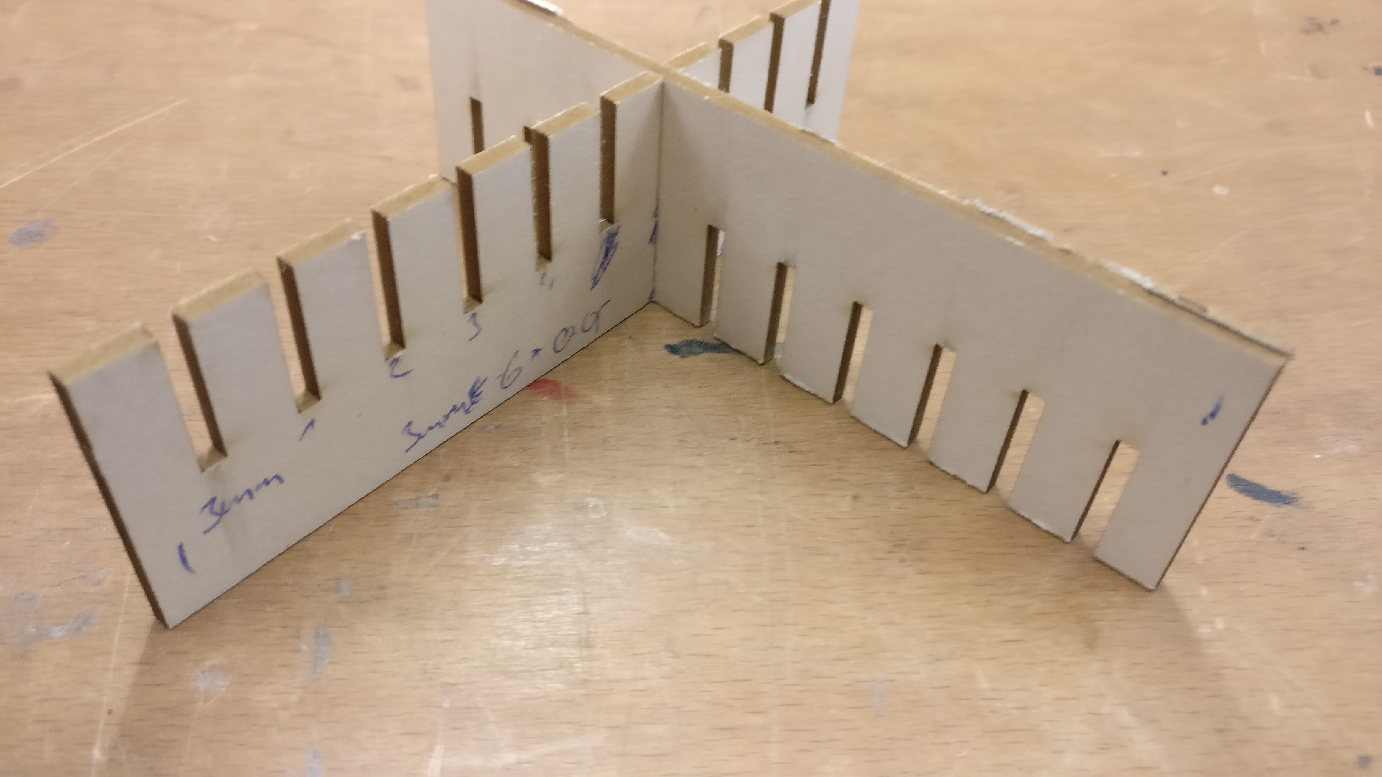
In order to design perfectly fitting press-fit kits we combined the previous experiments to a more practical approach. Look at the following pattern:
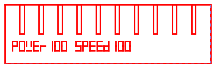
The comb features 10 slits starting at 3mm width on the left and decrease by 0.05mm to the right each. Using a different 3mm thick test piece you can find the ideal fit. We cut the same pattern twice and found the ideal fitting at 2.7mm intended slit. Note, that this does not necessarily correspond with the measured kerf width. Whereas stiffness and material density can influence the fit due to flexibility and strain of the material.
This pattern can also be cut at different parameter settings. The differences are barely visible when aligning the pieces but variations in friction can be observed while sliding in other test pieces.
Download the press-fit comb here (LaserScript file for VisiCut).