Embedded Programming
![]()
Introduction
For the assignment we were asked to read a microcontroller data sheet and program our board to do something, with as many different programming languages and programming environments as possible. In addition, we were asked to compare the performance and development workflows for other architectures as a Group Project.
Microcontroller Datasheet
So, I started by reading a data sheet in order to get a better understanding of what microcontroller I should choose for future Final Project. By now I already used two microcontrollers, so I started by reading their datasheet:
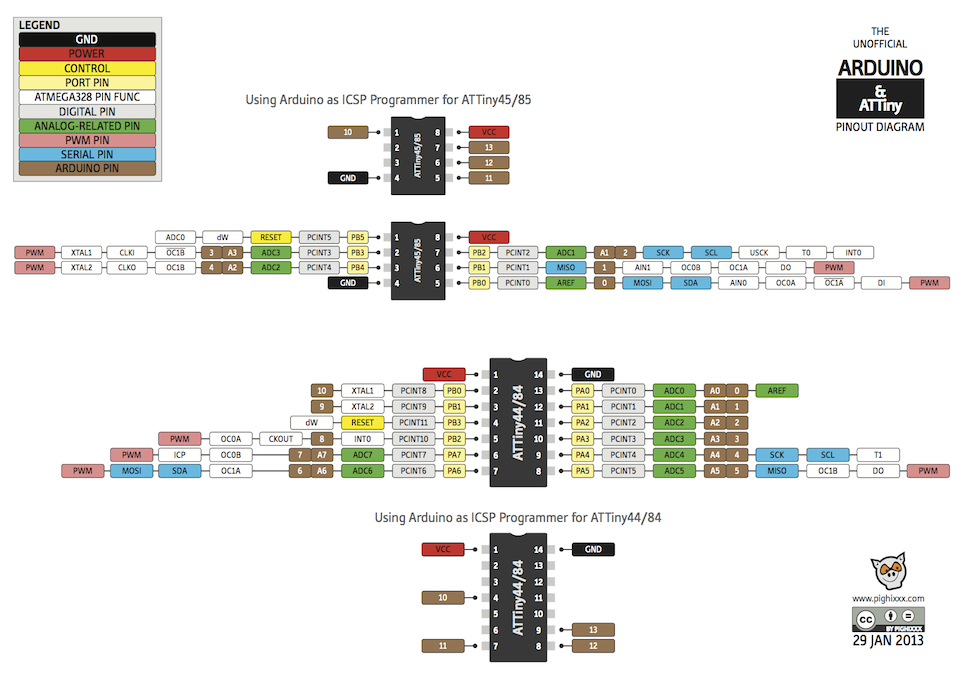
- Attiny45 which I used for 'Fab-ISP' in Electronics Production.
- Attiny44 which I used for 'Hello-World board' in Electronics Design.
As for my "begining" level of knowing microcontrollers, I found it really needed to double check the pinouts of microcontroller. Not only knowing about analog or digital is important. For instance, for connecting a Mosfet, not only digital pin is needed, but pin with PWM(Pulse-width modulation). It is a modulation technique used to encode a message into a pulsing signal. Pulse Width Modulation is used for getting analog results with digital means. Digital control is used to create a square wave, a signal switched between on and off. This on-off pattern can simulate voltages in between full on (5 Volts) and off (0 Volts) by changing the portion of the time the signal spends on versus the time that the signal spends off. The duration of "on time" is called the pulse width. To get varying analog values, you change, or modulate, that pulse width. If you repeat this on-off pattern fast enough with an LED for example, the result is as if the signal is a steady voltage between 0 and 5v controlling the brightness of the LED.
Another aspect mentioned in the datasheet are the clocks of a microcontroller. They always have an internal clock but if you want to make sure that when you communicate between two microcontrollers both have the same clock you can add an external one. The datasheet also shows you how to integrate this external clock into the circuit. More info about that can be found here.
Furthermore, a datasheet gives you information about the registers that are used when programming in plain C. I am using plain later in this assignment.
Unfortunately, I still did not finalize all the abilities I want to implement for it, but I am pretty sure that I need more pins than the Attiny 44 or 45 provides. So probably, I will choose ATmega328/P.
Since I already did the Fabrciation of an ISP assignment using the Arduino Uno microcontroller board, I had a bit of understanding how it works. But still, in order to have a better understanding how Arduino Uno works I read the schematick of the Arduino Uno first.
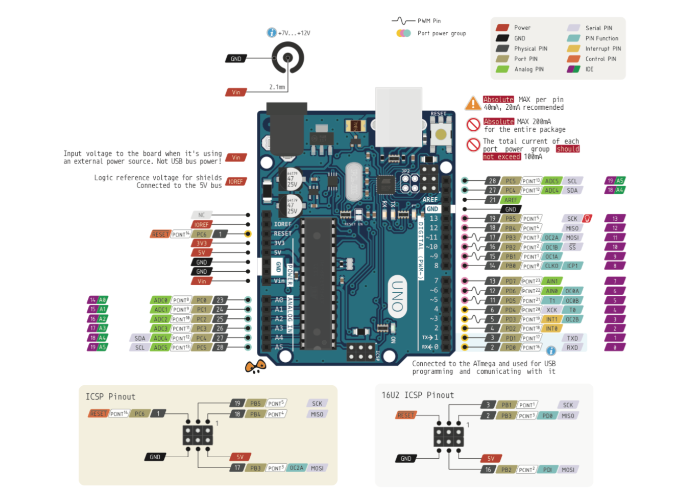
What is more, this picture shows how to use "Reset" on Arduino. What is more, in Arduino examples file(File/Examples/ArduinoISP/ArduinoISP) it is said "Use pin 10 to reset the target rather than SS".
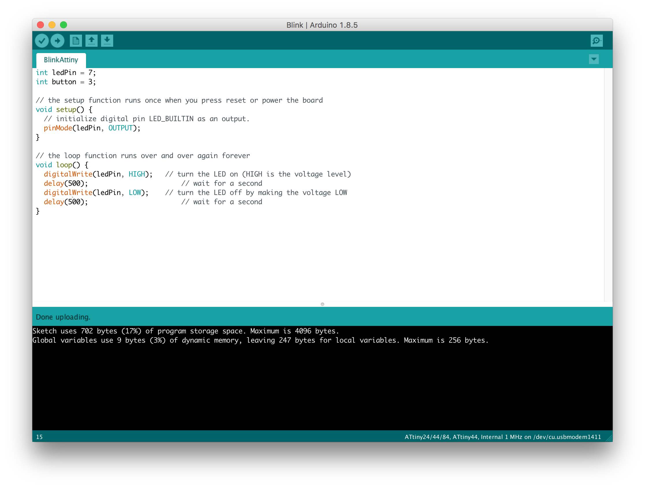
Afterwards, I had a look once again at the datasheet of the ATtiny44 which was used on the 'Hello-World board'. I used it to double-check which pin goes to LED the button. So, with my board LED pin is 7, Button is 3 (I need this for future programming).
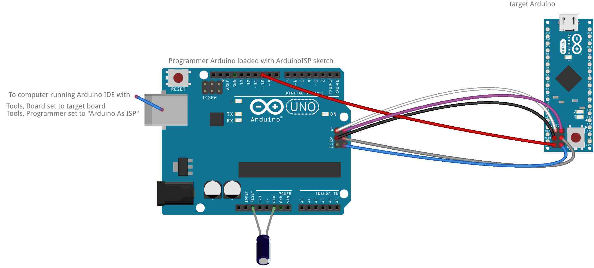
Connect Arduino and board
Based on all previous datasheets, connections of Arduino and Board was easy. The only recommendation I would give is to double-check that all pins are connected properly.
![]()
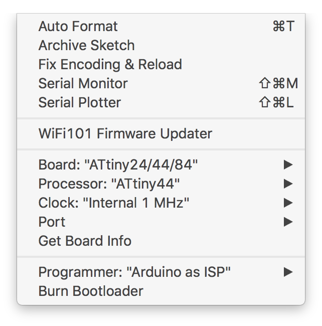
In order to set up Arduino and the board, I used this instruction. The main idea from here was how to setup Attiny 44. By default the Arduino IDE does not support it, so here is how to add it:
- In Arduino Preferences find Additional Board Managers URLs
- Paste the following URL "https://raw.githubusercontent.com/damellis/attiny/ide-1.6.x-boards-manager/package_damellis_attiny_index.json" there
- Press "OK" and restart the Arduino IDE
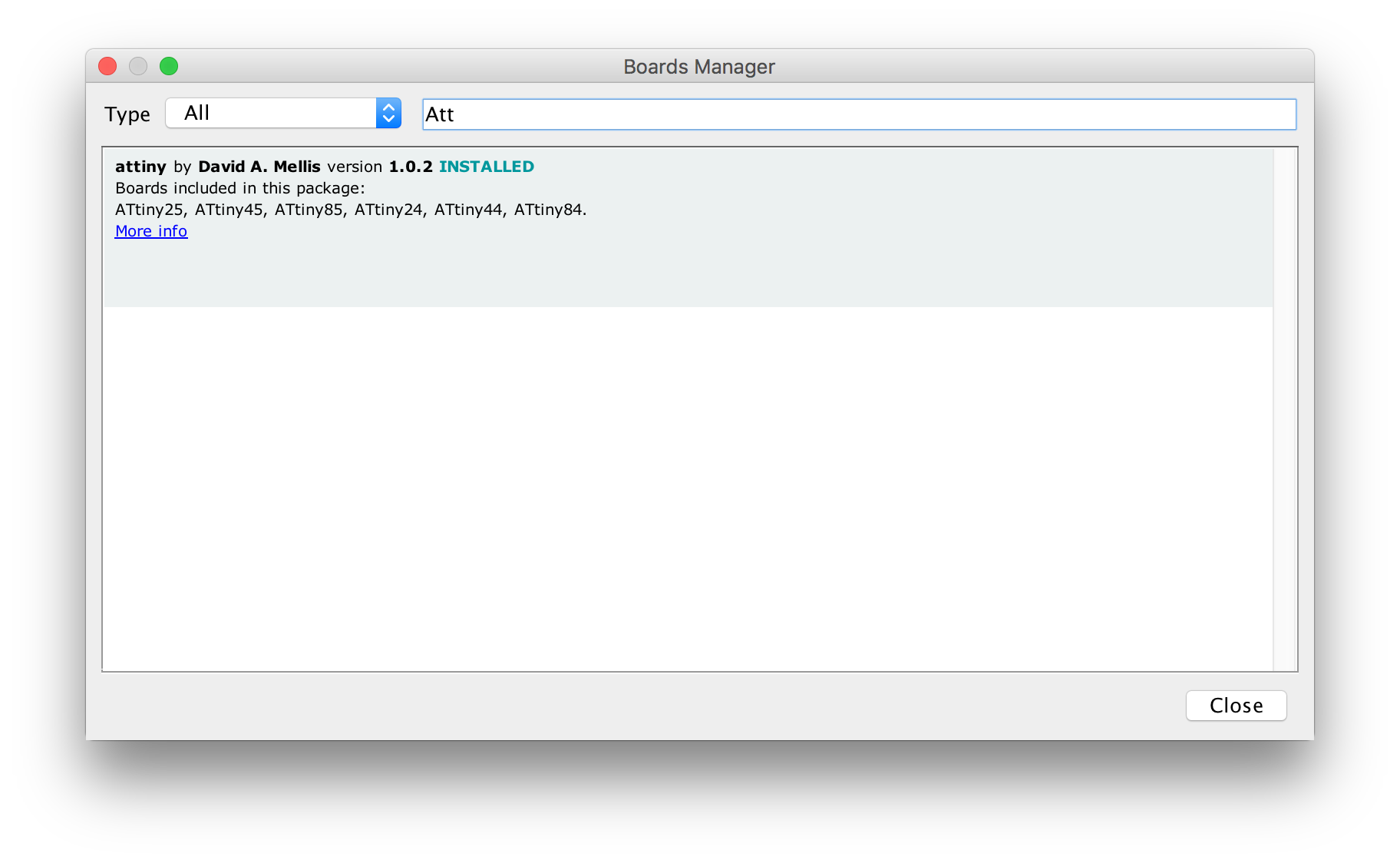
Now we need to install the ATtiny board package. That is how to do it:
- In Arduino Tools go to Board and then to Boards Manager
- Select Install on the Attiny by David. A Mellis
- Restart the Arduino IDE
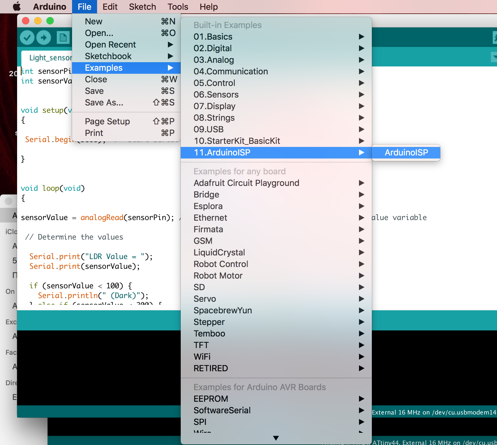
The next step would be to set the Arduino Uno Into ISP Mode. Note that during this stage you DO NOT connect the board you want to program to Arduino(otherwise you will get the mistake). Open Arduino as ISP example and run it:
Programming
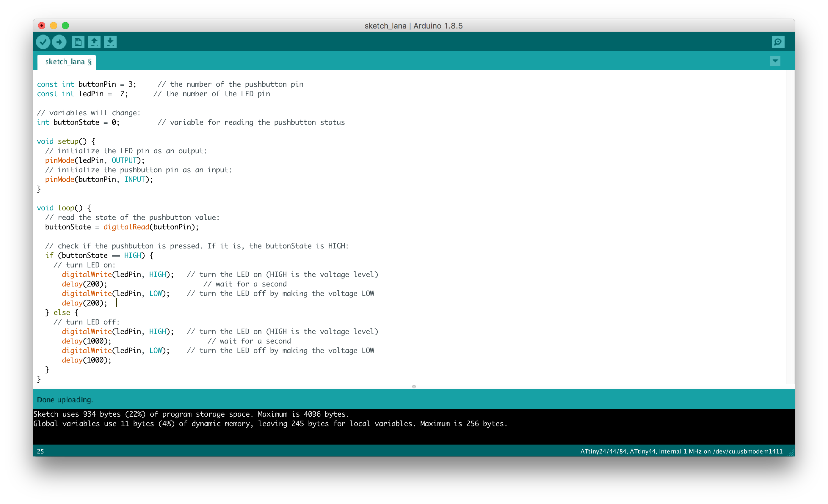
Now I started to play around with my board and try out different ways to make the LED blink and blink with different frequency, be turned on/off etc. So, programming the board was fun.
Make the LED blink (nothing depends on the button).
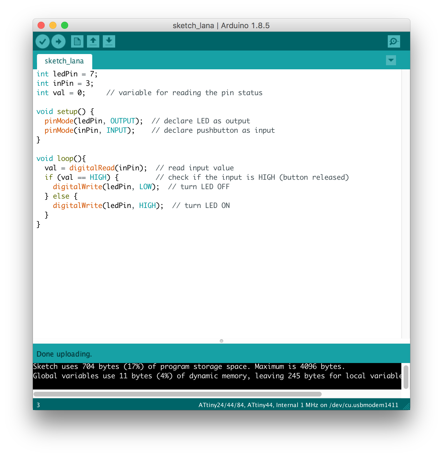
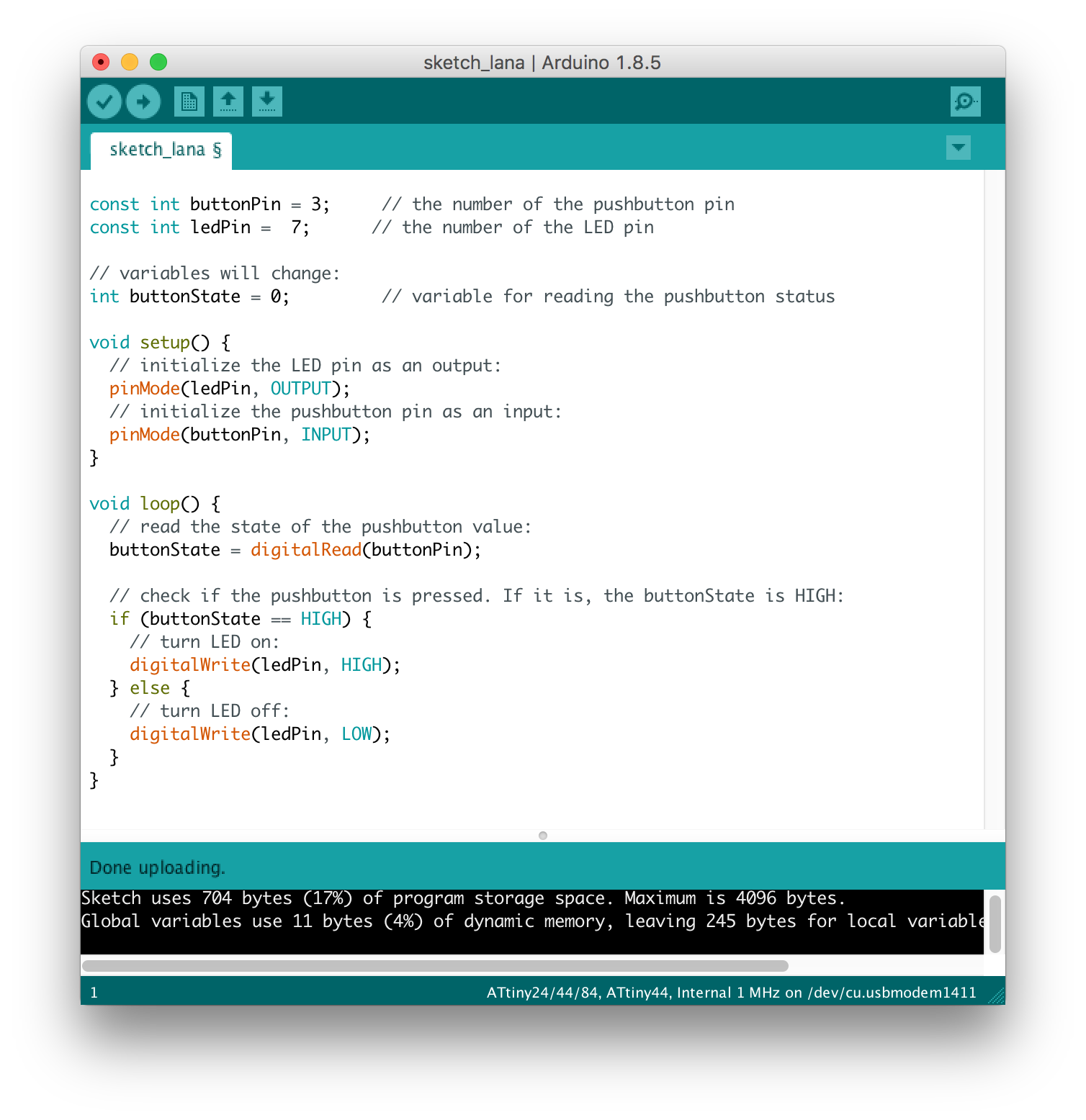
Turning the light on/off depending on pushing the button:
Changing the frequency of blinking (pushed/unpushed button)
AVR development
My next step was to try AVR board development. I wanna thank a lot our teammate Matthias for giving great instruction on AVR development. AVR is a family of microcontrollers developed by Atmel. The AVR is an architecture machine, where program and data are stored in separate physical memory systems that appear in different address spaces, but having the ability to read data items from program memory using special instructions. AVRs are programmed in C. Registers are the only way of interaction for a microprocessor.
I will again use my first board. I will write the program, that turns LED on and off via button. With AVR, if you want to light up an LED, you basically set the corresponding bit in the PORT register. There is a great Datasheet where I found a lot of useful information (for example, page 52 tells us about setting up an LED). What is more,
Before writing a code, make sure you have installed all the necessary software and libraries for AVR Programming. For that I used the Terminal in my mac. Here is commands that I used(line by line):
                ruby -e "$(curl -fsSL https://raw.githubusercontent.com/Homebrew/install/master/install)" < /dev/null 2> /dev/null
                brew install avrdude
                brew install avr-libc
                brew install libc6-dev
Then I wrote a simple code that I made.
                #include <avr/io.h>
                #include <util/delay.h>

                #define F_CPU 1000000L


                int main(void)
                {
                  DDRA |= (1<<PA7); //Nakes first pin of PORTC as Output
                  // OR DDRC = 0x01;
                  DDRA &= ~(1<<PA3);//Makes firs pin of PORTD as Input
                  // OR DDRD = 0x00; //Makes all pins of PORTD input
                  while(1) //infinite loop
                  {
                    if(PINA & (1<<PA3) == 1) //If switch is pressed
                    {
                      PORTA |= (1<<PA7); //Turns ON LED
                      _delay_ms(3000); //3 second delay
                      PORTA &= ~(1<<PA7); //Turns OFF LED
                    }
                  }
                }
Next step is to actually compile and upload the program. When you are at the same directory, as your program main.cpp and as your makefile, you can use next terminal commands:
                \\ avr compiler
                avr-g++ -mmcu=attiny44 main.cpp
                \\ after that a.out file should be created. Next step is:
                avr-objcopy -j .text -j .data -O ihex a.out main.hex
                \\ after that a hex-file, which is just another format compatible with the AVR. Now you can send the file to you board:
                avrdude -p t44 -c usbtiny -U lfuse:w:0x62:m -U hfuse:w:0xDF:m -U efuse:w:0xFF:m -U flash:w:main.hex:i
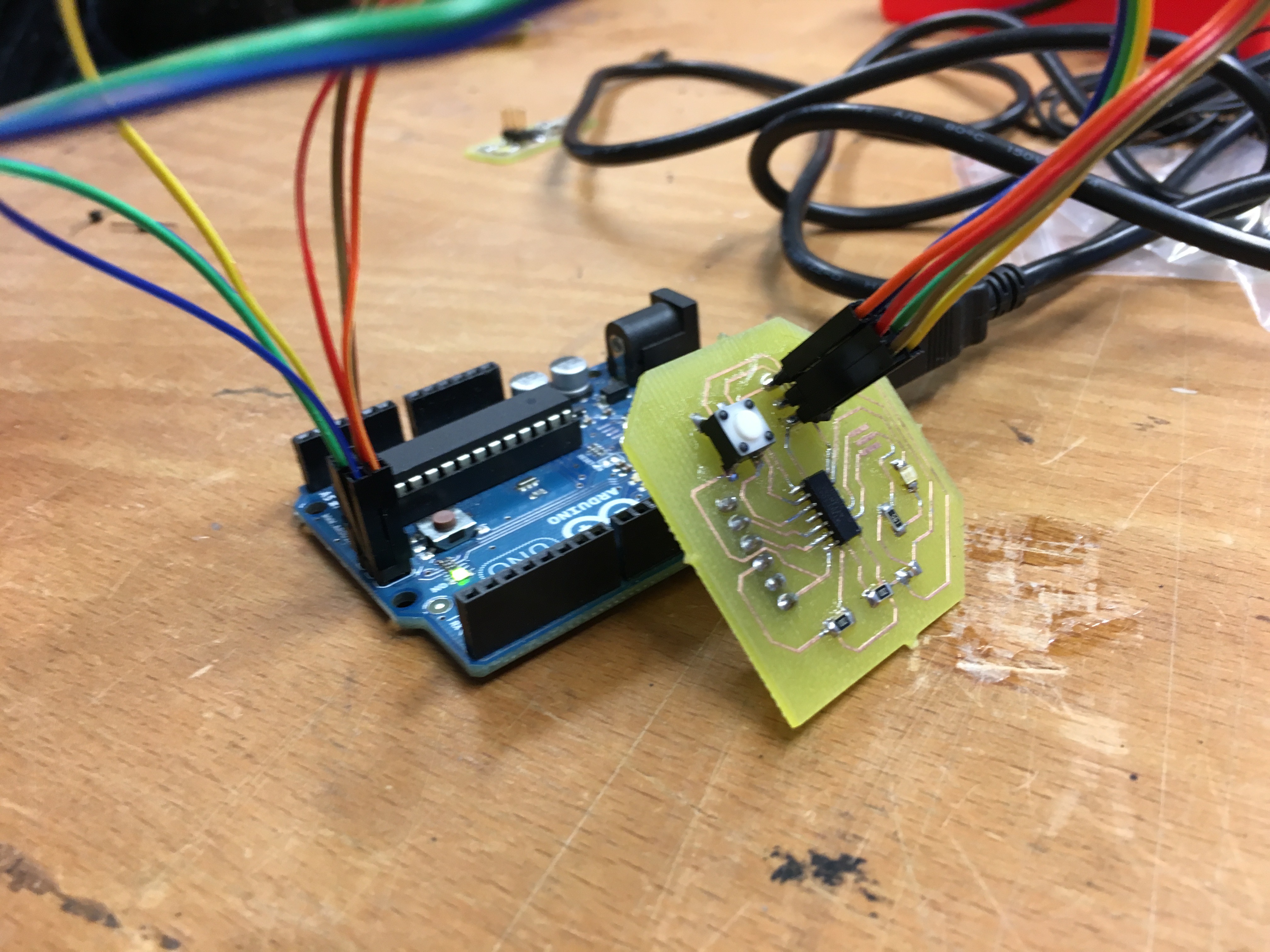
So now you can see the semo of my programmed with AVR using FabISP board: