SORTING OUT OUR SETUP
In our fablab we use windows computer to talk to our
Roland MDX-20 when we use this cnc machine for other operations than making Pcbs. The machine id connected using a coupled USB-RS232-Serial cable. This cable combination works great with Windows but creats a problem with data transfer between the computer and the MDX-20 when the g-code or the Roland version of the code is send through Fab Modules.
A separate Ubuntu partition was needed to be installed and an original serial-to-usb cable has to be used to send the code from fabmodules.
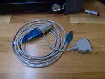 The USB-RS232-Serial cable that is used in the
Lab with Windows
The USB-RS232-Serial cable that is used in the
Lab with Windows
I switched to the mod_server
directory in terminal and ran the modules:
node mod_server.js
The server started and began listening for connections from 127.0.0.1 on 12345.
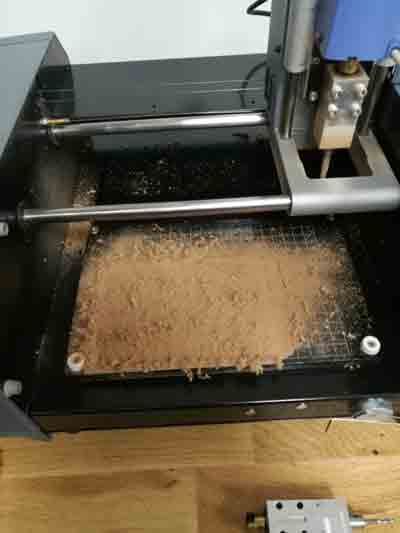
Next, I cleaned up the MDX-20’s buildplate and lasercut a new MDF spoilboard. I placed the board and use a 6mm tool to surface mill the board.
I also know from expirience that the machine's bed might not be completely on a flate so I wanted to serface mill the spoilboard to level everything with respect to the machines spindle.
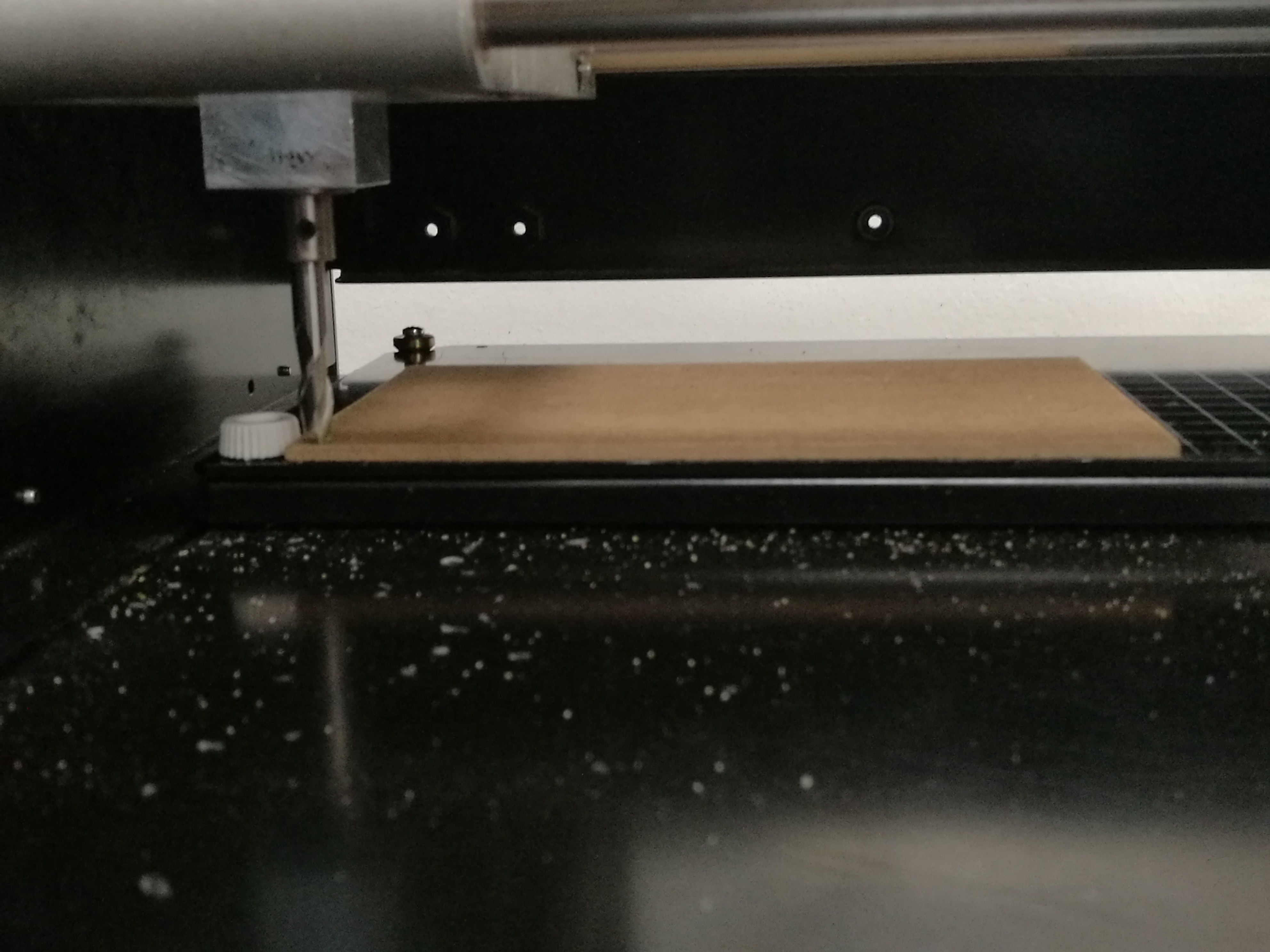 Our machine is physically ready!
From the Fab Modules website, I uploaded a .png file, selected .rml as the output format and PCB traces (1/64) for the process. From there, I could choose the MDX-20 from the machine dropdown and try sending a command.
I first wanted to try moving the spindle to x0 = 20, y0 = 20, z0 = 0. Sending the command with xyz0 threw the following error:
error: /bin/sh: 1: mod_serial.py: not founding
As described in the
Fab Modules troubleshooting
documentation, I checked that mod_serial.py was in the same
folder as mod_server.js and prefixed the send command with ./
alive!
FAB MODULES
Milling the PCB
Fab community offered variety of the FabISP designs to choose from. The evolution of the designs is by itself very interesting. I started with the one based on Dick Streefland's USBTiny FabTinyISP.
First I downloaded the files i.e. design that was available That included the traces and outline -files. Then I generated the milling files from .PNG pictures using Fab Modules. Software written by Neil. In Fab Modules, milling machine spesific settings has to be selected.
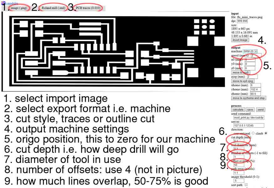 Fab modules setup
with the MDX-20
Fab modules setup
with the MDX-20
The cut depth field (6) setting in the above picture was
set to be 0.15mm which is deep enought to remove all the unwanted copper.
Number 8 defines how much
copper is removed next to a wire. If it is set to 1 the mill
bit will only make one pass, if the setting is for example 4, the
bit will run four parallel rounds I found setting 5 rounds will give proper distance with out compromissing the thinest areas and being more suitable to solder in the next step.
Setting number 9 defines how much these parallel runs
go on top of each other. If you use a V-shaped drill,
Some good overlap like 50-75% is good, so that all the copper
is removed. Select the starting position (5) for the starting cordinates. After defining all the settings press the
"calculate"-button. After calculation, press the "save"-button
to save generated milling file. When all is set and zero the tool (Z) press send.
 Fab modules setup
with the MDX-20
Fab modules setup
with the MDX-20
Milling the PCB
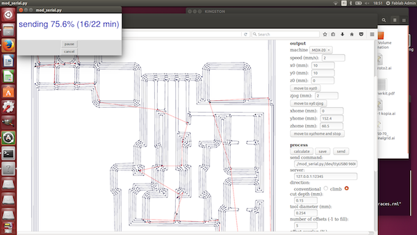
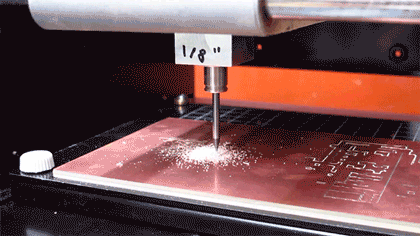 Milling the traces with 1/64” endmill
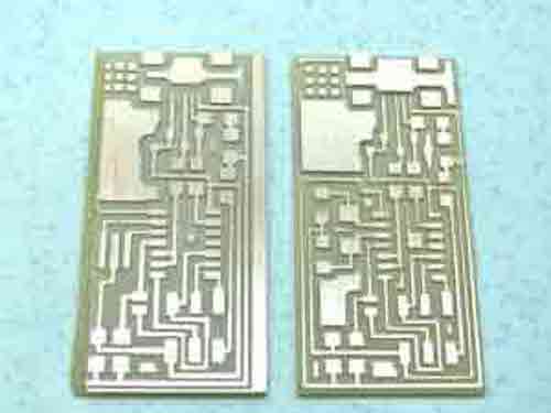
Notice the boarders on the left picture, the tracing and the cut out were not aligned properly. That was caused because the double sided tape I used behind the board and the sacrificial board was lose. On the right, the final board with all the Traces cut cleanly, with no issuesmat 0.15mm depth of cut and Board cutout in three passes using the 1/32” bit.
COMPONENT STUFFING
 Hello ISP 44 schematic:
http://academy.cba.mit.edu/classes/embedded_programming/hello.ISP.44.png
Hello ISP 44 schematic:
http://academy.cba.mit.edu/classes/embedded_programming/hello.ISP.44.png
| Qty. | Component | Marking(s) |
|---|---|---|
| 1 | ATtiny44 | ICt44 |
| 1 | 6-Pin Header | J1 ISP |
| 1 | USB Mini-B SMD Connector | J2 USB |
| 1 | Crystal 20 MHz | 20 MHz |
| 1 | Capacitor 1uF | C1 |
| 2 | Capacitor 10pF | C2, C3 |
| 2 | Diode Zener 3.3V | D1, D2 |
| 1 | Resistor 1k ohm | R1 |
| 1 | Resistor 499 ohm | R2 |
| 2 | Resistor 100 ohm | R3, R4 |
| 1 | Resistor 10k ohm | R5 |
| 1 | Resistor 0 ohm | SJ2 |
Bill of materials (BOM) *SJ1 is a solder jumper -
bridge with solder
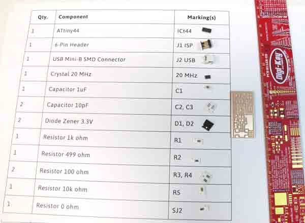 BOM print out help
me pick up the components
BOM print out help
me pick up the components
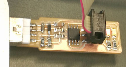
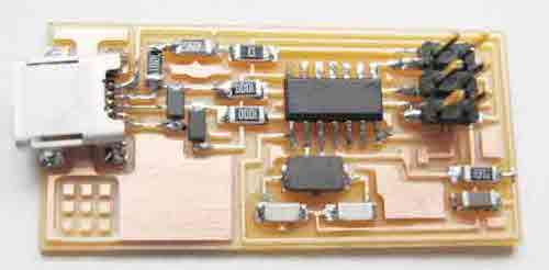 The board with all components mounted with shiny solder
joints
The board with all components mounted with shiny solder
joints
I then connected the board to the usb hub. Smoke test went without a hitch! That is great. I your computer shuts down or complains about too much power drain, check for a loss connection on the soldering.
PROGRAMMING THE ISP
We had an Adafruit AVR Programmer kit in the Lab, it wasn’t
built up, so I started putting it together. I completed the
assembly.
I connected the new FAbISP board to the programmer. The programmer LED turn Green a good sign that it correctly assumes that there is a new chip connected
 Error sign shows that there is a problem with the board. I unplugged the board and look for cold joints. And I found that the Attiny board Vcc was not even soldered! Done that Plugged it back! and It is alive.
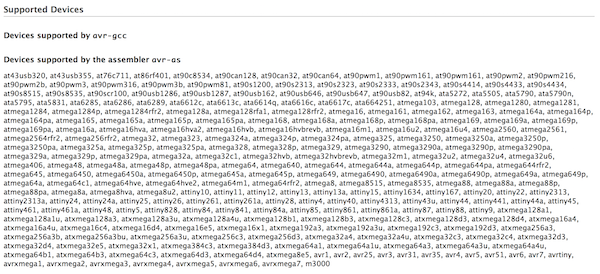
To send the Makefile to the FabISP, I first needed to install an AVRprogramming application. I’m running Mac OS, so I chose Crosspack AVR .
 The list of supported devices is amazing
I downloaded the FabISP Firmware from the Fab Academy documentation, I didn't have to edit the programmer configuration in the Makefile as the Adafruit AVR Programmer is already set as the programming unit
AVRDUDE = avrdude -c avrisp2 -P usb -p $(DEVICE) # edit this line for your programmer
Now to compile the firmware:
cd Downloads/fabISP_mac.0.8.2_firmware
make clean
A positive response should be:
rm -f main.hex main.lst main.obj main.cof main.list main.map main.eep.hex main.elf *.o usbdrv/*.o main.s usbdrv/oddebug.s usbdrv/usbdrv.s
Make Hex:
make hex
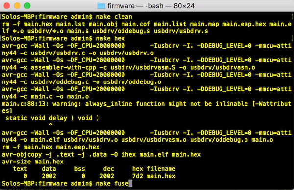
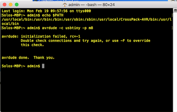
Next, set the fuses so the board will use the external crystal:Make fuse
make fuse
Response:
avrdude -c stk500v1 -b19200 -P /dev/tty.usbmodem1411 -p attiny44 -U hfuse:w:0xDF:m -U lfuse:w:0xFF:m

avrdude: stk500_getparm(): (a) protocol error, expect=0x14, resp=0x14

avrdude: stk500_getparm(): (a) protocol error, expect=0x14, resp=0x01
avrdude: stk500_initialize(): (a) protocol error, expect=0x14, resp=0x10
avrdude: initialization failed, rc=-1
         Double check connections and try again, or use -F to override
         this check.

avrdude: stk500_disable(): unknown response=0x12

avrdude done.  Thank you.

make: *** [fuse] Error 1
Oh dear. At this point, I inspected the board closely for cold joints or visible shorts and realised I hadn’t soldered the pins on the back of the USB header at all! I also had a 4.99 Ohm resistor in place of the 499 Ohm resistor. Lesson learned: don’t trust that resistors have been put in the correct draw in the component tower - always check the component markings.
With those problems fixed, I attempted to set the fuses again (this time using sudo to run my command):
sudo make fuse
Still I had the same error message, even after checking carefully for shorts with a multimeter, so I abandoned the Arduino and tried using a FabISP made by Ali Neissi .
I changed the programmer config to:
AVRDUDE = avrdude -c usbtiny -p $(DEVICE)
Then ran:
sudo make fuse
Response:
avrdude -c usbtiny -p attiny44  -U hfuse:w:0xDF:m -U lfuse:w:0xFF:m

avrdude: AVR device initialized and ready to accept instructions

Reading | ################################################## | 100% 0.00s

avrdude: Device signature = 0x1e9207
avrdude: reading input file "0xDF"
avrdude: writing hfuse (1 bytes):

Writing | ################################################## | 100% 0.00s

avrdude: 1 bytes of hfuse written
avrdude: verifying hfuse memory against 0xDF:
avrdude: load data hfuse data from input file 0xDF:
avrdude: input file 0xDF contains 1 bytes
avrdude: reading on-chip hfuse data:

Reading | ################################################## | 100% 0.00s

avrdude: verifying ...
avrdude: 1 bytes of hfuse verified
avrdude: reading input file "0xFF"
avrdude: writing lfuse (1 bytes):

Writing | ################################################## | 100% 0.00s

avrdude: 1 bytes of lfuse written
avrdude: verifying lfuse memory against 0xFF:
avrdude: load data lfuse data from input file 0xFF:
avrdude: input file 0xFF contains 1 bytes
avrdude: reading on-chip lfuse data:

Reading | ################################################## | 100% 0.00s

avrdude: verifying ...
avrdude: 1 bytes of lfuse verified

avrdude: safemode: Fuses OK (H:FF, E:DF, L:FF)

avrdude done.  Thank you.
That’s more like it!
sudo make program
Response:
avrdude -c usbtiny -p attiny44  -U flash:w:main.hex:i

avrdude: AVR device initialized and ready to accept instructions

Reading | ################################################## | 100% 0.00s

avrdude: Device signature = 0x1e9207
avrdude: NOTE: "flash" memory has been specified, an erase cycle will be performed
     To disable this feature, specify the -D option.
avrdude: erasing chip
avrdude: reading input file "main.hex"
avrdude: writing flash (2002 bytes):

Writing | ################################################## | 100% 1.96s

avrdude: 2002 bytes of flash written
avrdude: verifying flash memory against main.hex:
avrdude: load data flash data from input file main.hex:
avrdude: input file main.hex contains 2002 bytes
avrdude: reading on-chip flash data:

Reading | ################################################## | 100% 2.32s

avrdude: verifying ...
avrdude: 2002 bytes of flash verified

avrdude: safemode: Fuses OK (H:FF, E:DF, L:FF)

avrdude done.  Thank you.

avrdude -c usbtiny -p attiny44  -U hfuse:w:0xDF:m -U lfuse:w:0xFF:m

avrdude: AVR device initialized and ready to accept instructions

Reading | ################################################## | 100% 0.00s

avrdude: Device signature = 0x1e9207
avrdude: reading input file "0xDF"
avrdude: writing hfuse (1 bytes):

Writing | ################################################## | 100% 0.00s

avrdude: 1 bytes of hfuse written
avrdude: verifying hfuse memory against 0xDF:
avrdude: load data hfuse data from input file 0xDF:
avrdude: input file 0xDF contains 1 bytes
avrdude: reading on-chip hfuse data:

Reading | ################################################## | 100% 0.00s

avrdude: verifying ...
avrdude: 1 bytes of hfuse verified
avrdude: reading input file "0xFF"
avrdude: writing lfuse (1 bytes):

Writing | ################################################## | 100% 0.00s

avrdude: 1 bytes of lfuse written
avrdude: verifying lfuse memory against 0xFF:
avrdude: load data lfuse data from input file 0xFF:
avrdude: input file 0xFF contains 1 bytes
avrdude: reading on-chip lfuse data:

Reading | ################################################## | 100% 0.00s

avrdude: verifying ...
avrdude: 1 bytes of lfuse verified

avrdude: safemode: Fuses OK (H:FF, E:DF, L:FF)

avrdude done.  Thank you.
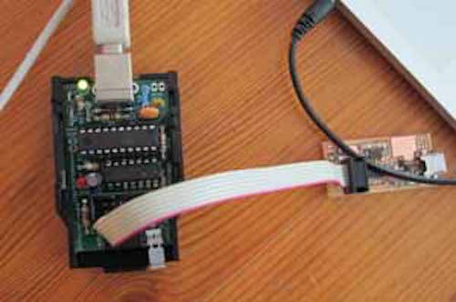
Yiiihewwww! With that, I verified that the FabISP was identified correctly.
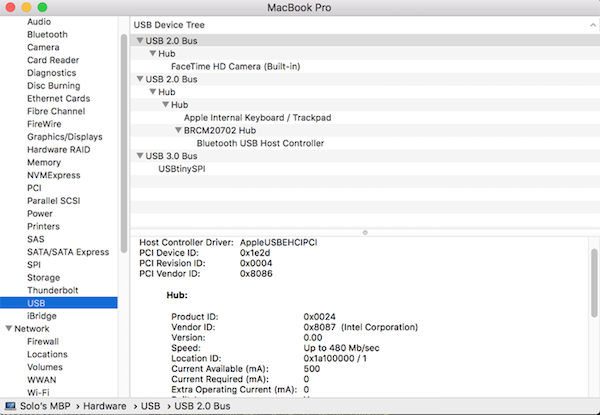 The FabISP making friends with my Macbook
All good! Finally I desoldered jumpers SJ1 and SJ2, then went for a beer!
The second board
Fab community offers multiple of designs of the Fab-ISP from where to choose. I wanted to make the one made by Brian called FabTinyISP as it has a dirrect USB support.
First I downloaded the files i.e. design that was available That included the traces and outline -files. Then I generated the milling files from .PNG pictures using Fab Modules. Software written by Neil. In Fab Modules, milling machine spesifications were the same as I described earlier. This was very good exercise and I have learned a lot and have so much fun!
Files
FabISP Traces (14kB) -
hello-ISP44_traces.png
FabISP Cutout (12kB) -
hello-ISP44_interior.png
Links
Fab Academy 2016 -
Electronics Production
FabISP Programming Tutorial -
FabISP: Programming
FabISP Troubleshooting -
FabISP: Electronics Production