Output Devices
Download all the files for this week from here
For group assignment visit here.
Add an output device to a micro-controller board you’ve designed and program it to do something.
Design the controller board for the final project
For this week’s assignment I decided to design the the controller board that I will use for my final project. Both the Input & Output devices are done together on the same board.
In my final project, The barrel of the extruder is to be heated at a set temperature, this will be done by 3 cartridge heaters. To measure the Temp a 100k Thermistor will be used.
BOM
- 1 X 100K NTC Thermistor.
- 3 X Ceramic heater cartridge 24V 40W
- 1 X DC geared motor 14V 8Nm Torque
- 1 X Power supply 24V 15A
- MICRO ATMEGA328P-AU
- Q1 16Mhz Crystal
- C1, C2 18pF
- C3, C4 100nF
- R1-R8 10K
- R8, R9 0ohm
- Q2-Q5 IRF3710S N-FET 100V 57A
- Q7 IOR
- D1-D5 DIODE 1N4001
- 7 X Screw terminal
- 1 X MTA02-156 male connector
- 1 X SMD male header 5X2 connector
Heating Cartridge
The heating cartridge I’m using are of 12V and 40W. Mosfet will be used as a switch to turn on and off the heating cartridge since Arduino cannot supply the required power.
Mosfet used - IRF540N. Datasheet can be find here.
Basic Connections :
Electronic Design
I decided to make a DIY Arduino and us an ATMEGA328P-AU to control the nozzle temperature. I will use a 100K NTC Thermistor same as in a 3D printer to have accurate temperature measurements. To heat the nozzle I will use 3 Ceramic heater cartridge and for the same I will need 3 mosfet, 1 more MOSFET for the DC geared motor.
How I designed the Board.
So the first thing was to decide which microcontoller to use.I decided to use an ATMEGA328P-AU instead of using the Attiny44, since I’d be needing a lot more i/o and PWM ports, also more memory.
The internet is full of DIY Arduino, just have to search Hackaduino and you are good to go.
One such reference i got for the basic schematic was from How-To: Perfboard hackduino. It’s very simple and use very little component to get going.
Also i looked at Satshakit for basic schematic and the selection of crystal frequency and capacitors.
After the basic schematic it went on to add a voltage regulator circuit since input voltage to the board is 12v which is regulated to 5v on board for atmega 328p and 12v raw for the heating cartridges. Here is a basic schematic i found on the internet.
 .
Source - Here
.
Source - Here
Schematic
Kindly open the image in new tab as to zoom and see the image clearly.
- File’s Name in the source folder : Input/Output.sch
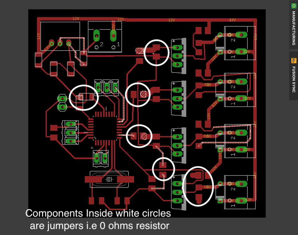
Board
- Image of final board
- Unrouted Nets
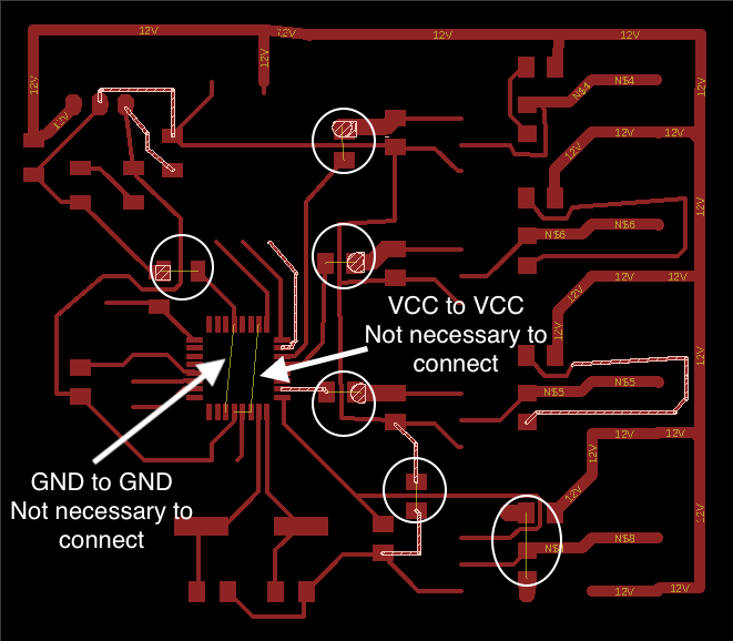
Image showing jumpers which are the unrouted nets.
File’s Name in the source folder : Input/Output.sch
Traces
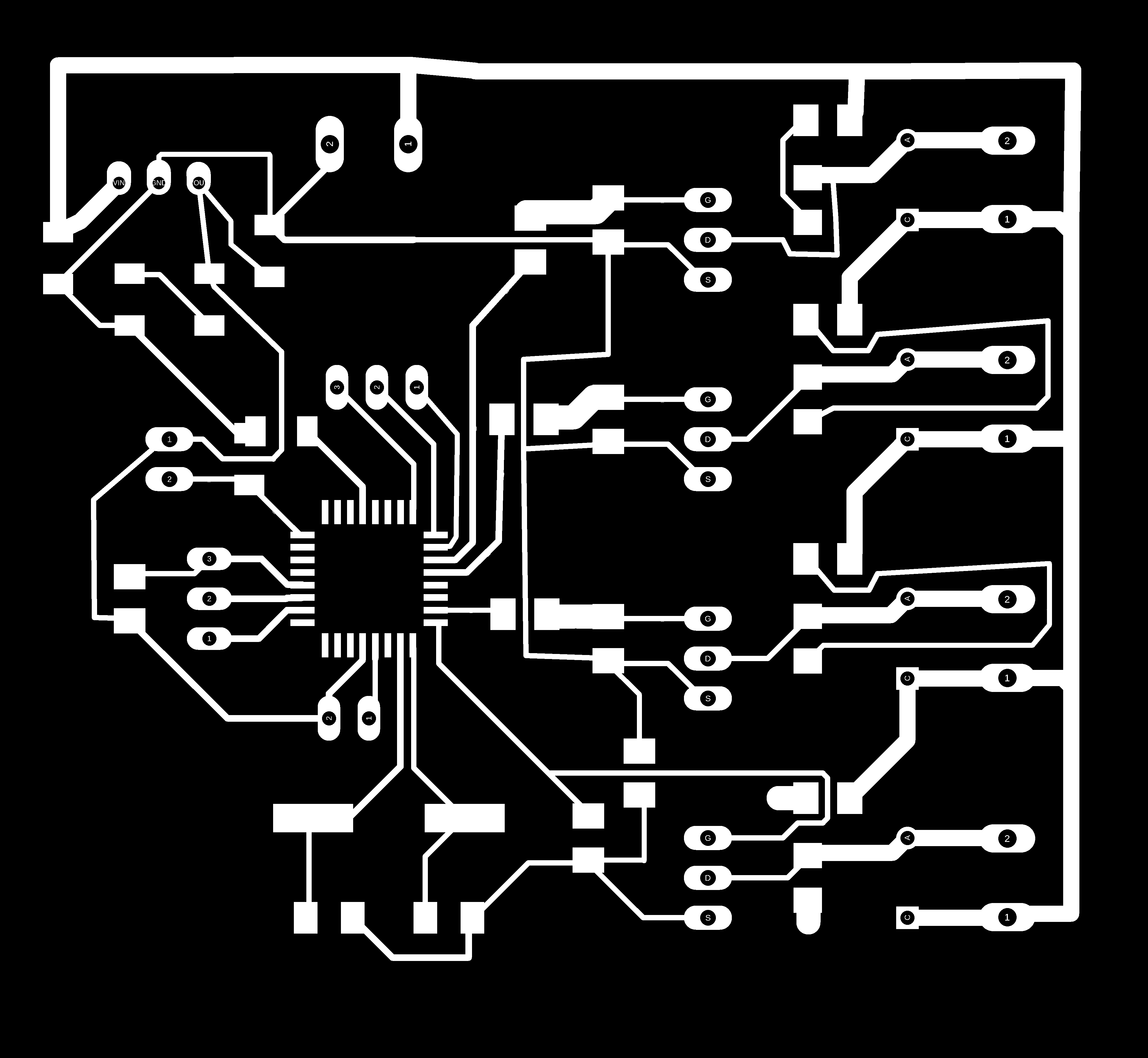
- File’s Name in the source folder : traces.png
Milling:
- Milling the board was pretty tricky since 328P-AU has very tiny footprint.
The Atmega 328 package i was using had very low clearance b/w the footprints. I edited the cad of the model and made the footprint small and have more clearance.
To mill the board I have used the same process described in week 5. After couple of tries I was able to mill the perfect board.
Final Board
Here is the milled board stuffed with all the components.
Front–
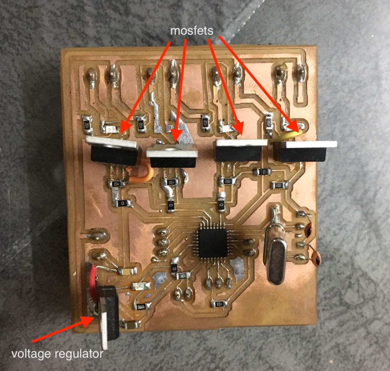
Back–
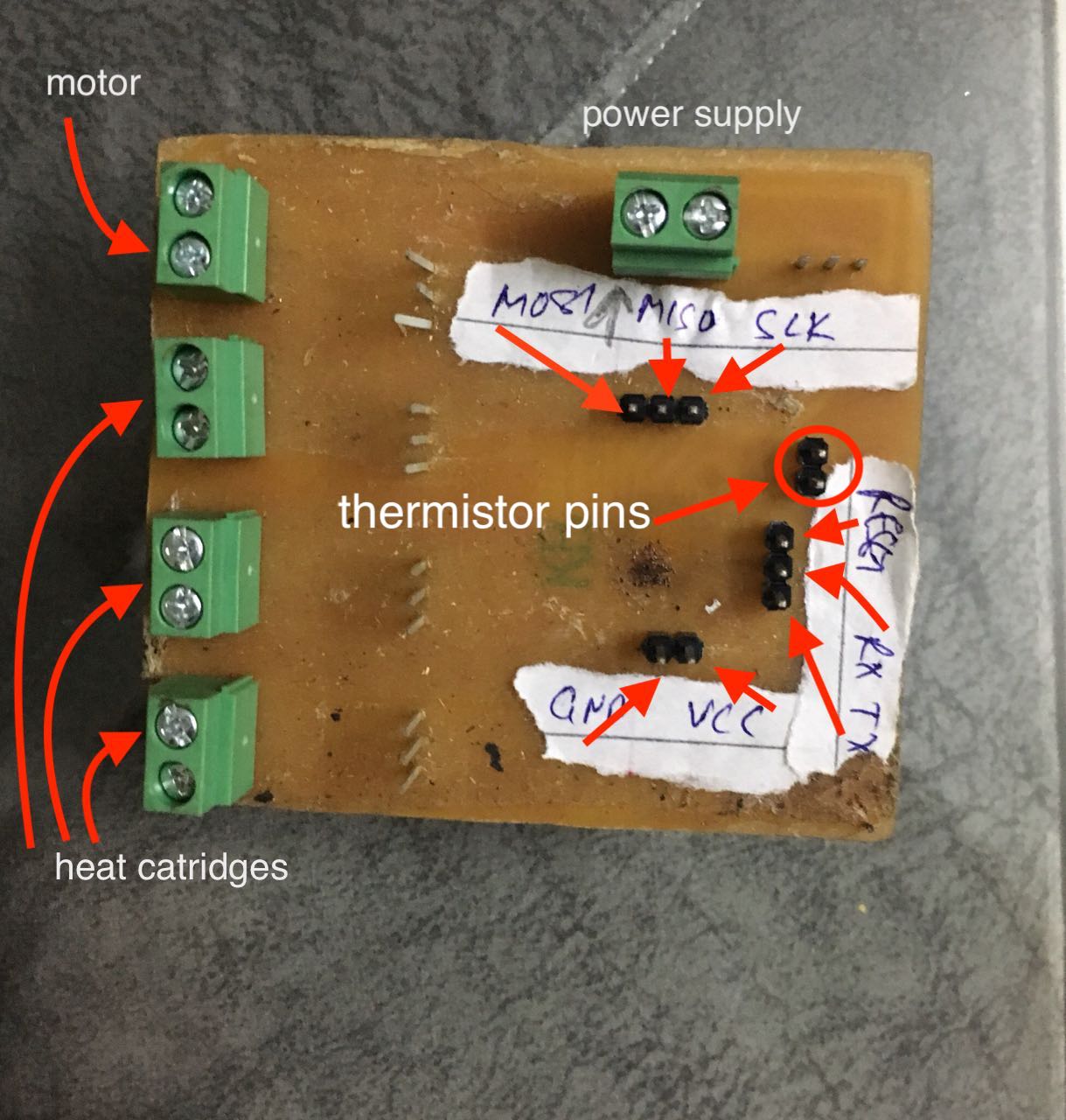
Here I have marked the programming and the Serial communication pins for better understanding. These pins are used to programme the board and also communicate using a FTDI cable. Bothe of the processes are mentioned in week-9 & week-13.
Programming the board
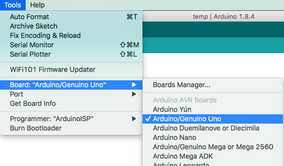
- Programming the board is pretty simple. I used a 16mhz clock with 22pf resistor to make sure that the Arduino IDE recognises my board as Arduino UNO which it did.
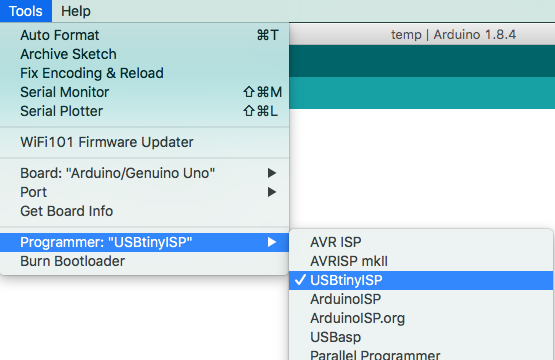
- I used FabISP to programme the board. Here is the picture of my board marked with the IPSheader pins ; MISO MOSI VCC GND RESET SCK. Connect these to the respective ISP i[ins on the programmer and you are good to go.
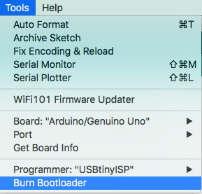
- After that You need to burn the bootloader. The fuses are set when the bootloader is dumped to the MCU.
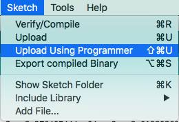
- The final step is to programme the board, You ned to upload select upload using programmer in order to burn the code to the MCU.
- Done Uploading.
Arduino Output Code
Understanding PWM
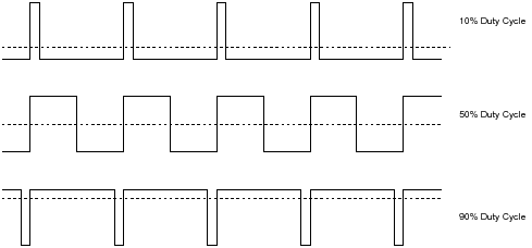
- Pulse-width modulation (PWM), or pulse-duration modulation (PDM), is a modulation technique used to encode a message into a pulsing signal.
Below you can see how output signal looks like with the duty cycle.
For better understanding of PWM Signals refer this LINK.
In my programme the PWM signals control the On/Off of mosfet which i turns the On/Off of the Heat Cartridge. This is done because if a constant power is supplied to the heat Cartridge it may get damaged, hence power is supplied in cycles. Also this helps in heating up the Cartridge to a desired temp and maintaining that temperature.
- The MOSFET is controlled using an analog signal/voltage. In order to have an analog voltage, you need a DAC (Digital-to-analag converter) but since you don’t have one, you use PWM (analogWrite -terrible name for this function - ref:. By changing the pulse width, you change the average voltage supplied hence controlling the MOSFET’s current output. The PWM signal acts as a tap valve controlling the current (not ON/OFF - this would be a switch) which adjusts the flow of current, which in turn can control the temperature of the heater cartridge. ( explained by my global instrcutor : Rodney )
int ThermistorPin = A2; //Thermistor attached at analog pin A2
int Vo;
float R1 = 10000; //voltage divider resistor value
float logR2, R2, T;
float c1 = 1.009249522e-03, c2 = 2.378405444e-04, c3 = 2.019202697e-07; //thermistor co-efficients
#define H1 10
#define H2 9
#define H3 6

void setup() {
Serial.begin(9600);
pinMode(H1, OUTPUT); //setting pin H1 as output, goes to the first mosfet which controls the Heat Cartridge.
pinMode(H2, OUTPUT);//setting pin H2 as output, goes to the second mosfet which controls the Heat Cartridge.
pinMode(H3, OUTPUT);//setting pin H4 as output, goes to the third mosfet which controls the Heat Cartridge.
}

void loop() {
   //PWM signal values were adjusted manually by trial and error, the main aim was to have the temp being maintained at around 220 degree Celsius.
 {analogWrite(H1, 172); //PWM signal set 172, to heat the cartridge H1
 analogWrite(H2, 172);//PWM signal set 172, to heat the cartridge H2
 analogWrite(H3, 172);//PWM signal set 172, to heat the cartridge H3
 delay(15000); //Rest period of 15 seconds for the heating cartridge
 analogWrite(H1, 20); // PWM signal set to 20, Does't let the cartridge cool Down completely
 analogWrite(H2, 20);/ PWM signal set to 20, Does't let the cartridge cool doewn completely
 analogWrite(H3, 20);/ PWM signal set to 20, Does't let the cartridge cool down completely
 }
 //Below is the temp input code

  Vo = analogRead(ThermistorPin);
  Serial.println(Vo);
  Serial.println(Vo);
  R2 = R1 * (1023.0 / (float)Vo - 1.0);
  logR2 = log(R2);
  T = (1.0 / (c1 + c2*logR2 + c3*logR2*logR2*logR2));
  T = T - 273.15;
  T = (T * 9.0)/ 5.0 + 32.0;
  Serial.print("Temperature: ");
 // Serial.print(T);
  float C= (T-32);
  float P= 0.5555;
  float temp= C*P ;
  Serial.println(temp);
  Serial.println(" C");

  delay(500);
- File’s Name in the source folder - output.ino
Video
- The heating cartridge was able to melt the filament easily.