Download all the files for this week from here
For group assignment visit here.
For this week’s assignment, I designed a simple GUI on Processing. Since I was running behind and had to complete my rest of the assignments, I decided to do something simple this week just for the sake of completion (bad). I shall update the page with more stuff once I have enough time.
GUI - Processing
- After discussing with my instructor, I decided to use Processing. It’s very Arduino like. After going through a couple of tutorials I got the hang of it and within sometime was able to design the GUI.

- Here is a simple tutorial on Processing which I followed :
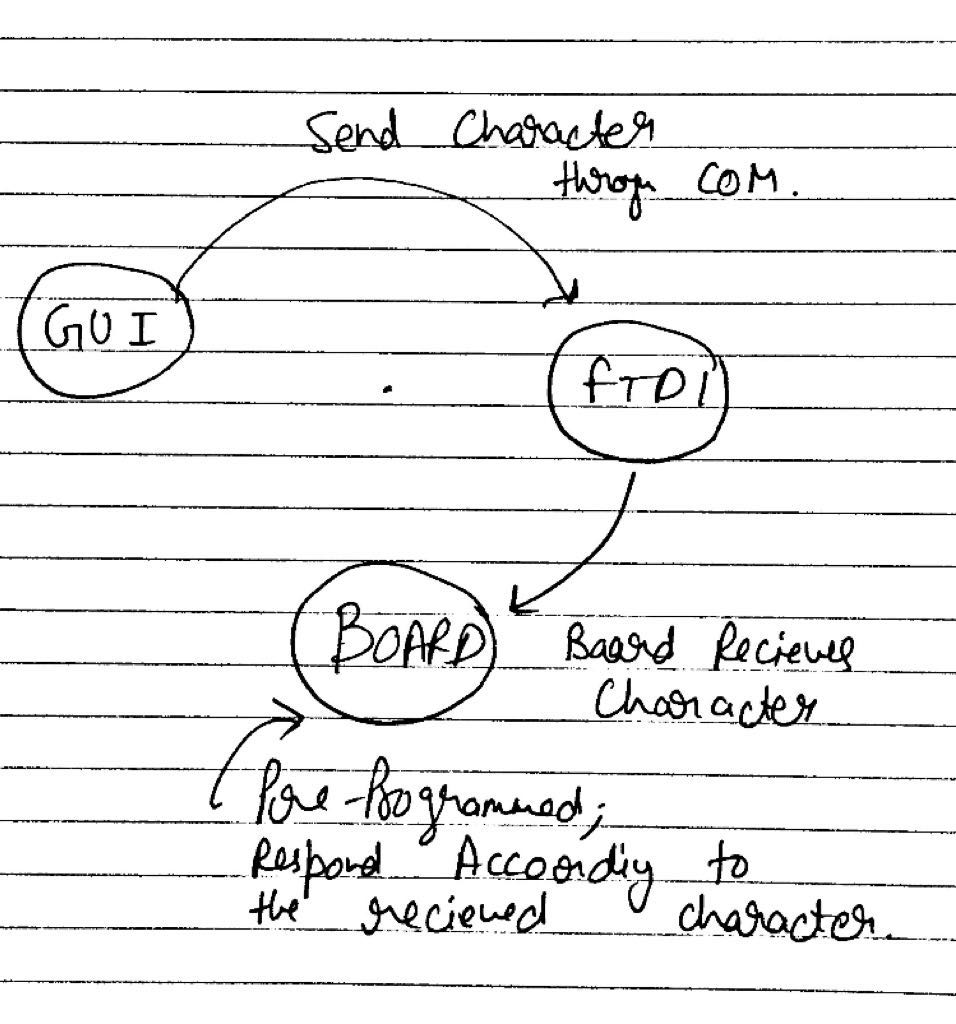
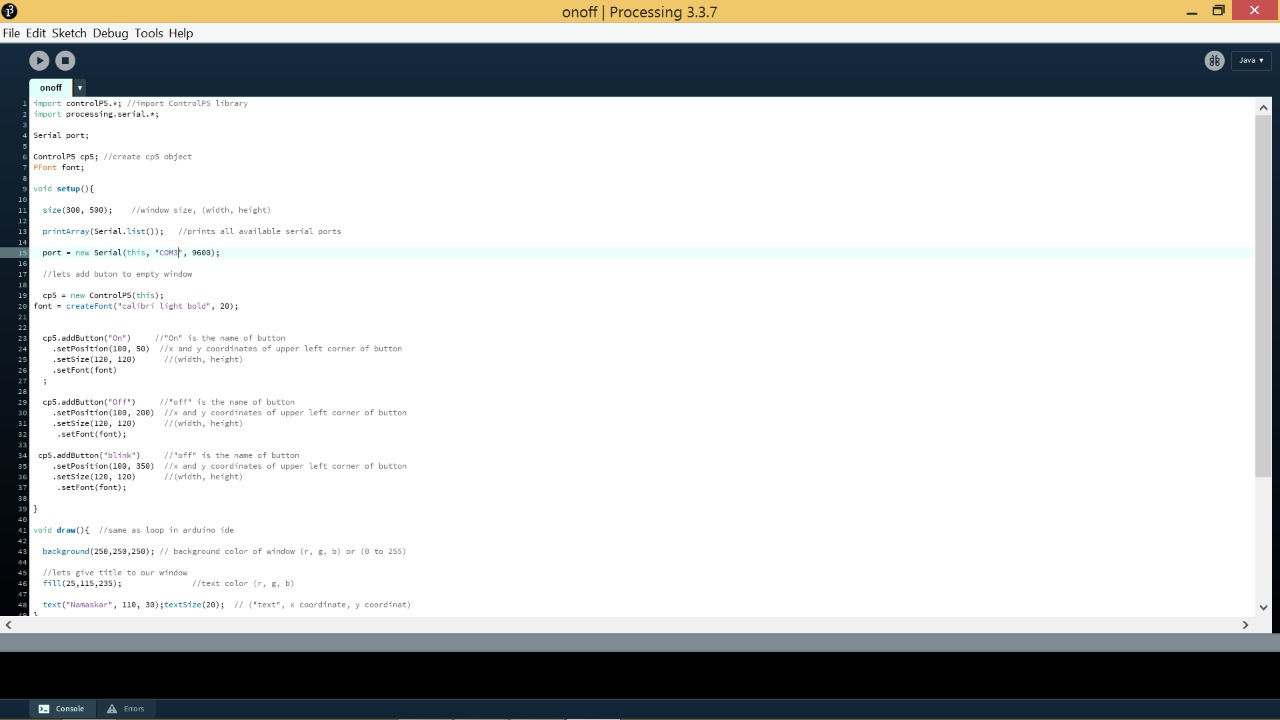
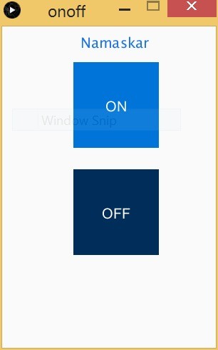
- I wrote a program which has two buttons, an On and a OFF button to control and LED. The LED code is written in Arduino.Processing and the code in the Microcontroller communicate through serial communication.
-
import controlP5.*; //import ControlP5 library
import processing.serial.*;

Serial port;

ControlP5 cp5; //create cp5 object
PFont font;

void setup(){

size(300, 450);    //window size, (width, height)

printArray(Serial.list());   //prints all available serial ports

port = new Serial(this, "COM10", 9600);

//lets add buton to empty window

cp5 = new ControlP5(this);
font = createFont("calibri light bold", 20);


cp5.addButton("On")     //"On" is the name of button
.setPosition(100, 50)  //x and y coordinates of upper left corner of button
.setSize(120, 120)      //(width, height)
.setFont(font)
;

cp5.addButton("Off")     //"off" is the name of button
.setPosition(100, 200)  //x and y coordinates of upper left corner of button
.setSize(120, 120)      //(width, height)
.setFont(font);


}

void draw(){  //same as loop in arduino ide

background(250,250,250); // background color of window (r, g, b) or (0 to 255)

//lets give title to our window
fill(25,115,235);               //text color (r, g, b)

text("Namaskar", 110, 30);textSize(20);  // ("text", x coordinate, y coordinat)
}


//so when you press any button on the GUI, it sends perticular char over serial port

void On(){
port.write('o');
}

void Off(){
port.write('f');
}
File’s Name in the source folder : onoff.pde
Here is the GUI :
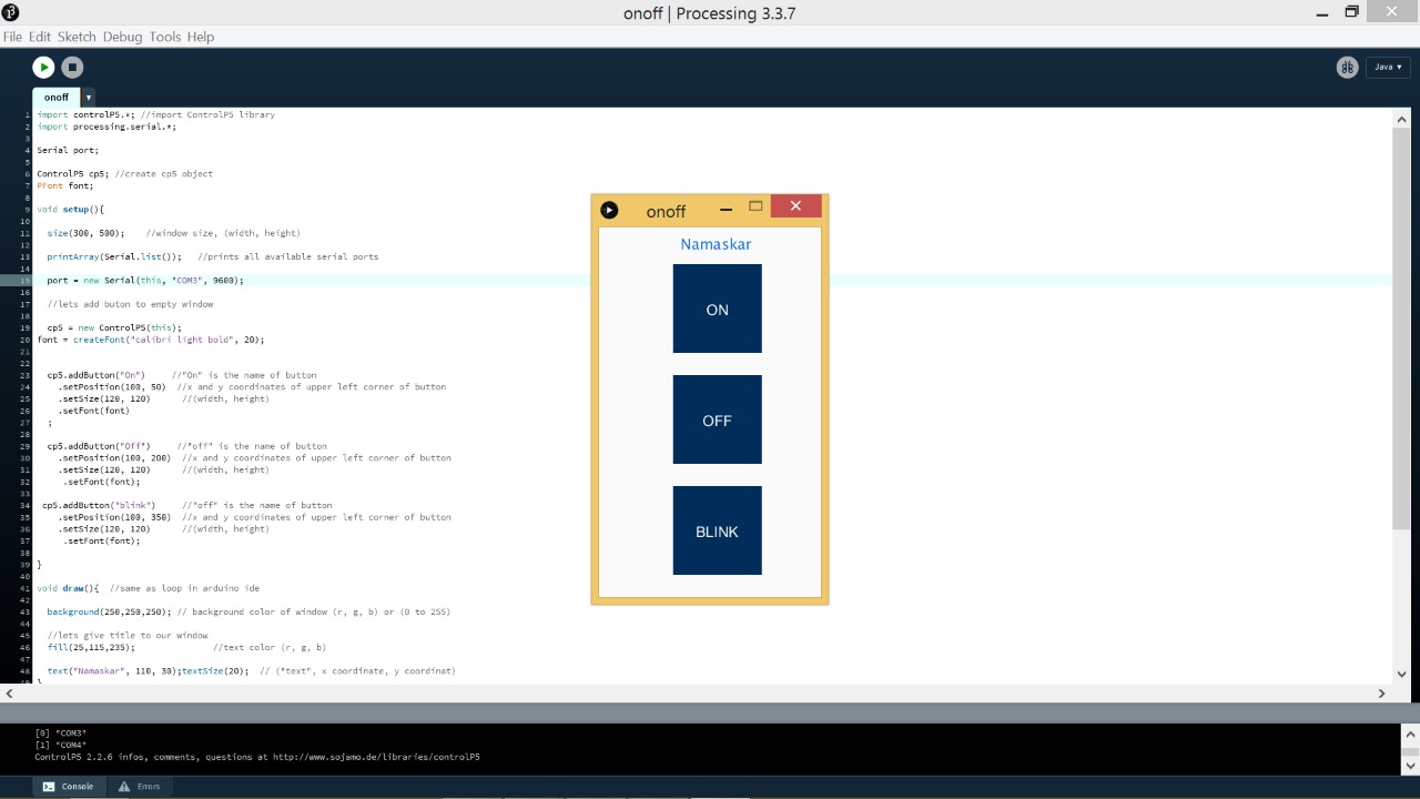
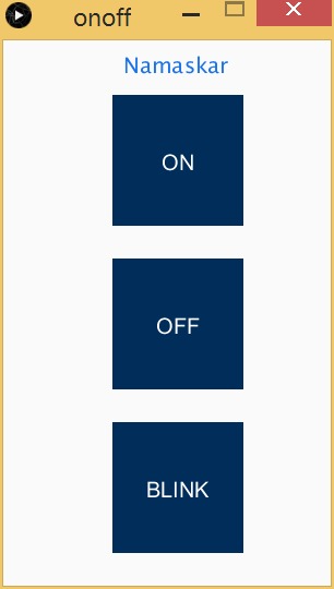
- I added a Blink Button also :
Arduno/Microcontroller Code
After the GUI, I wrote a simple Arduino code to turn an LED on and OFF. When a button is pressed in the GUI it sends a particular character, the character is read by the microcontroller to recognize whether to turn ON or OFF the LED.
If ‘o’ is received it will turn on the LED and if ‘f’ is received it will turn off.
Here is the Code :
void setup() {

pinMode(2, OUTPUT);


Serial.begin(9600);
}

void loop() {

if (Serial.available()) {

char val = Serial.read();

if (val == 'o') {
  digitalWrite(2, HIGH);
}
if (val == 'f') {
  digitalWrite(2, LOW);
}

}
}
File’s Name in the source folder : onoffarduino.ino
File’s Name for updated code in the source folder : final.ino
Video :
In the video i’m using an Arduino since my board was not working, shall update it in sometime.
[Update] After debugging the board i found some connections loose and also the LED was burnt. I rectified the board and it was working perfect.
Video - Self Fabricated Board from week - 7 :
ANDROID APPLICATION
- A fellow student had used App Inventor to make an android app. The interface seemed easy and the workflow too.
- After a week, I decided to make an app also. I wanted to control the LED from the APP via Bluetooth just like I did in processing.
- I started with Basic Videos from YouTube and in an hour I got the hang of it.
- App Inventor has been very easy to use, just pick and place components and your done.
For the icons in the app, I found an amazing website with tons of icons to choose from - icons8.com
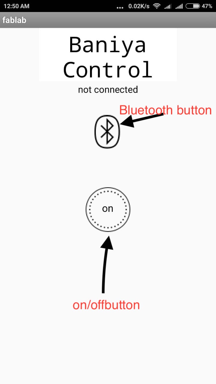
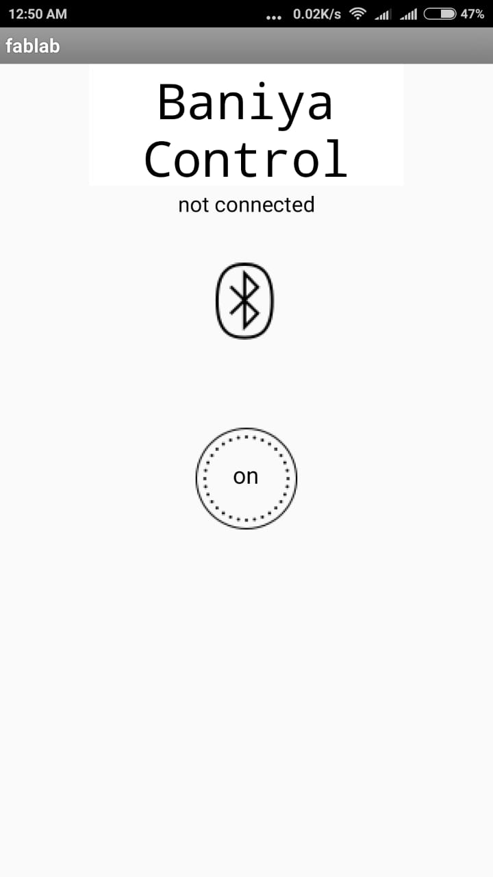
Here is my Application Window :
- App Inventor Desinge Window with icons & layout.
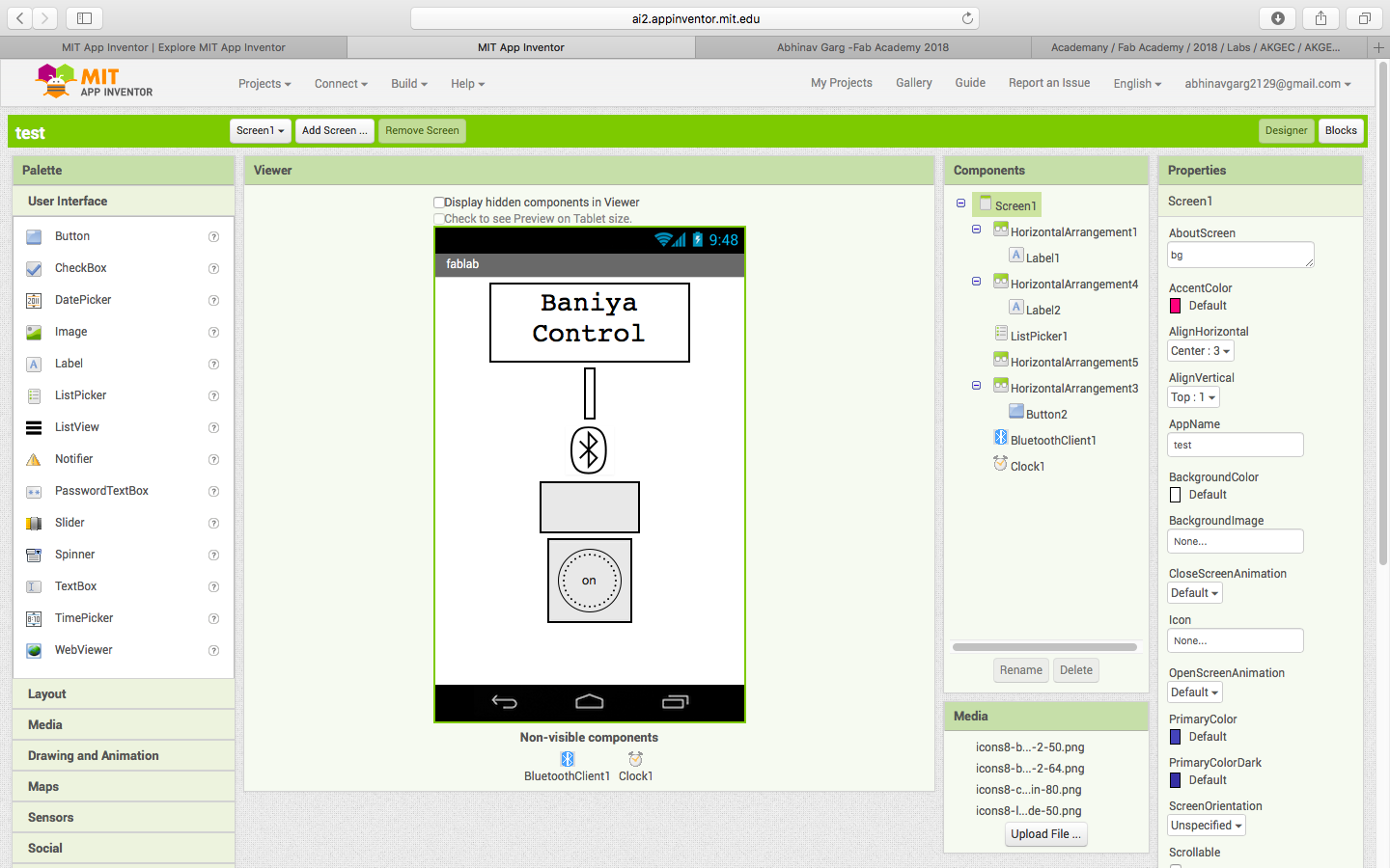
- App Inventor Blocks Window, were you connect certain buttons, images wth one another and also command them to do something.
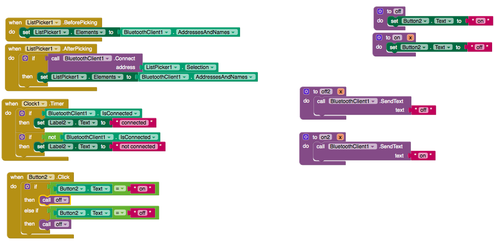
- In my app, a person first clicks the Bluetooth icon which opens a list of Nearby Bluetooth device, After connecting with the required Bluetooth device, You can press the ON/OFF button to control the LED’s of Board.