Let the Boards Talk
Download all the files for this week from here
- For this week we had to communicate between two or more boards, either send them signal from the computer,app or make one of the boards master and the rest slave.
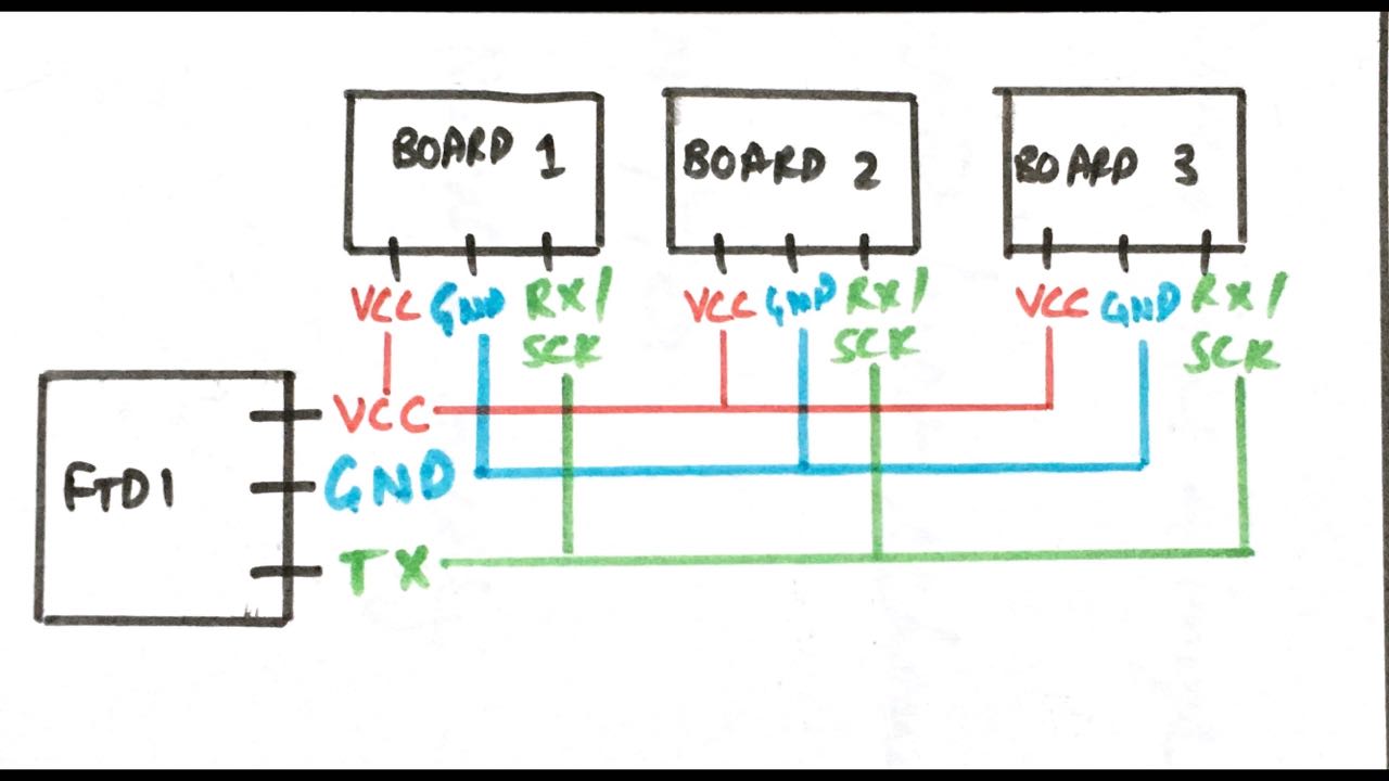
- Here is the initial sketch i made, all the board will be connected to a common VCC, GND and RX/SCK pins. When a Particular board is called it responds by switching on the LED.
Development Boards
I’ll be using 3 boards, one board from week 7 and for the rest of the boards I’ll modify the week 7 board and removing the FTDI headers and the button.
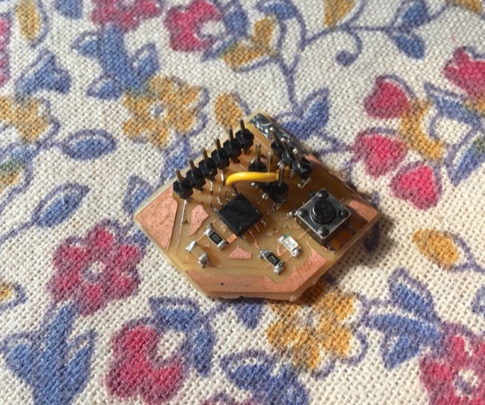
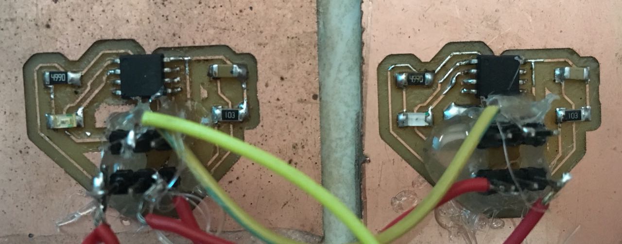
The node board which is remixed from week 7 only has LED, ISP header and Attiny-44. They are simple to mill and solder.
Main Board
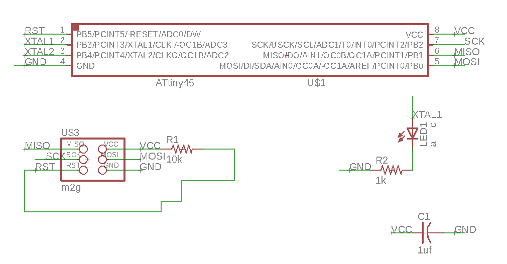
Here is my board from week 7.
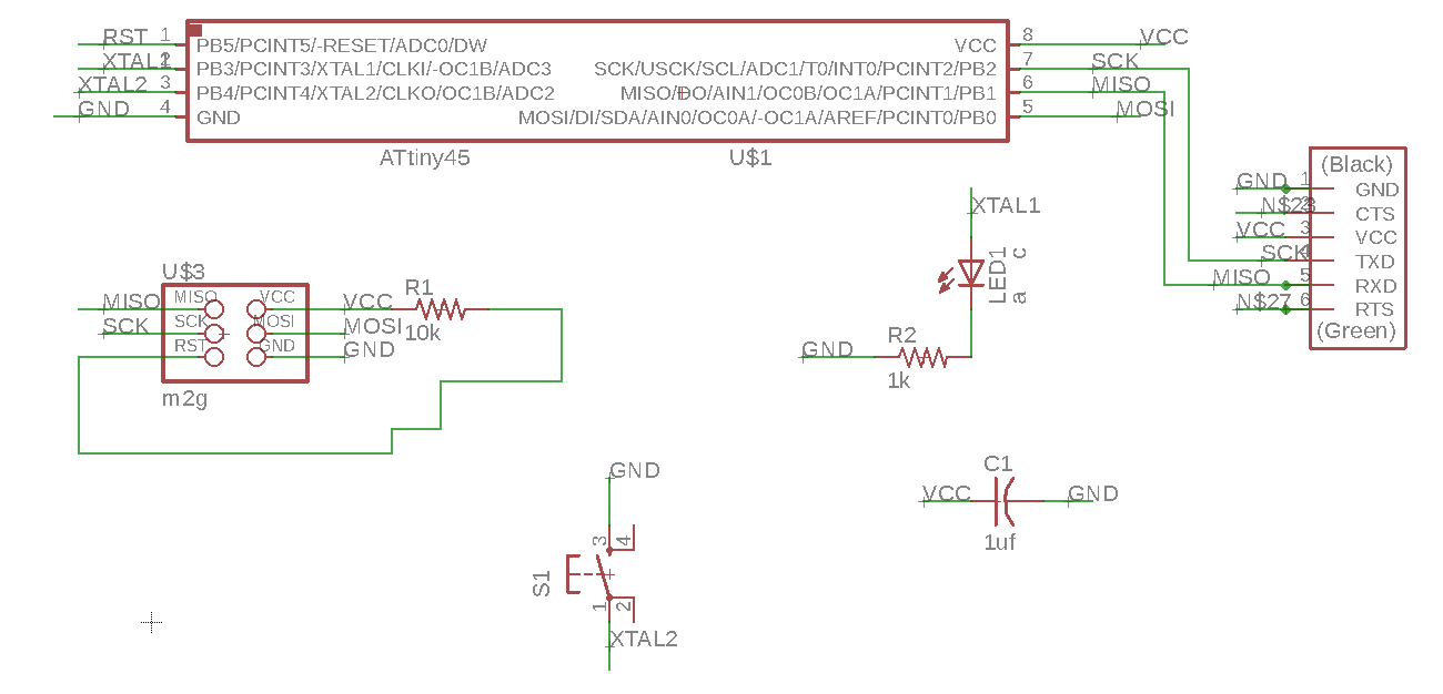
- File’s Name in the source folder : week7-small.sch
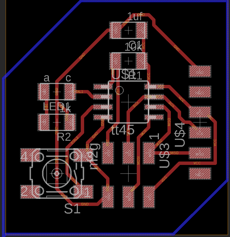
- File’s Name in the source folder : week7-small.brd
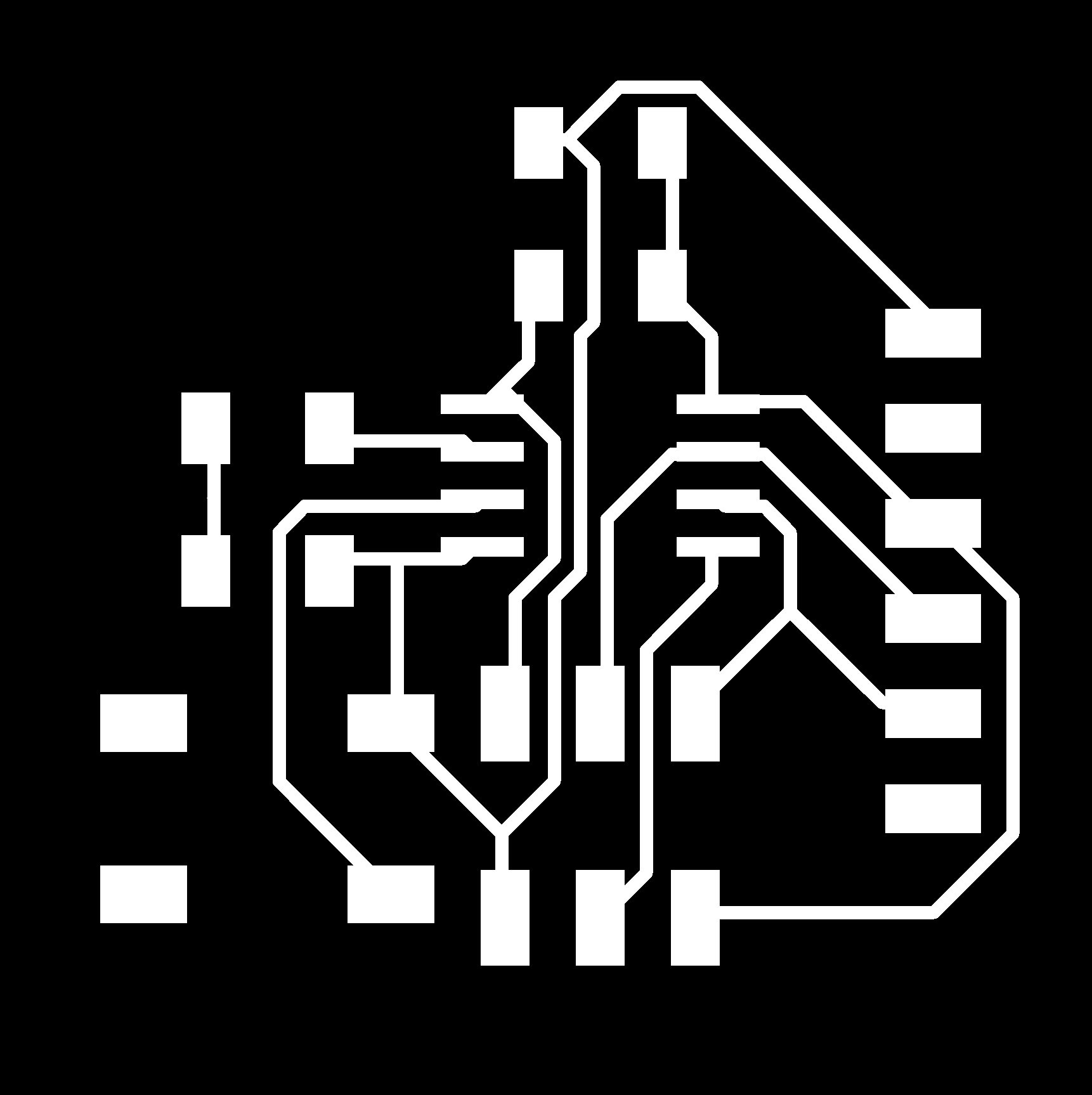
- File’s Name in the source folder : week7-small.png
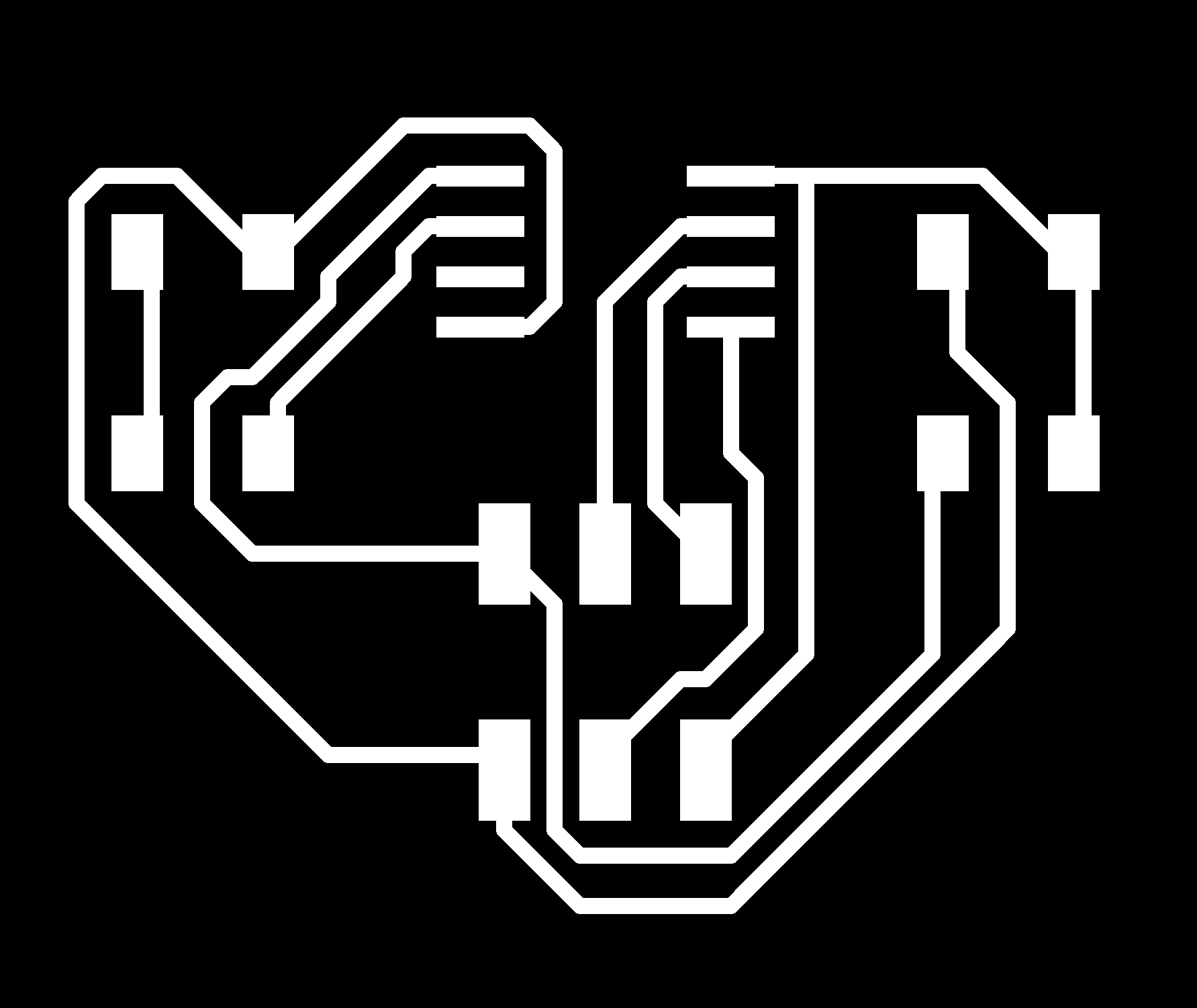
Remixed Board
- Board remixed from the week 7 board. Here the FTDI and Switch were omitted.
File’s Name in the source folder = week7-small-noftdi.sch
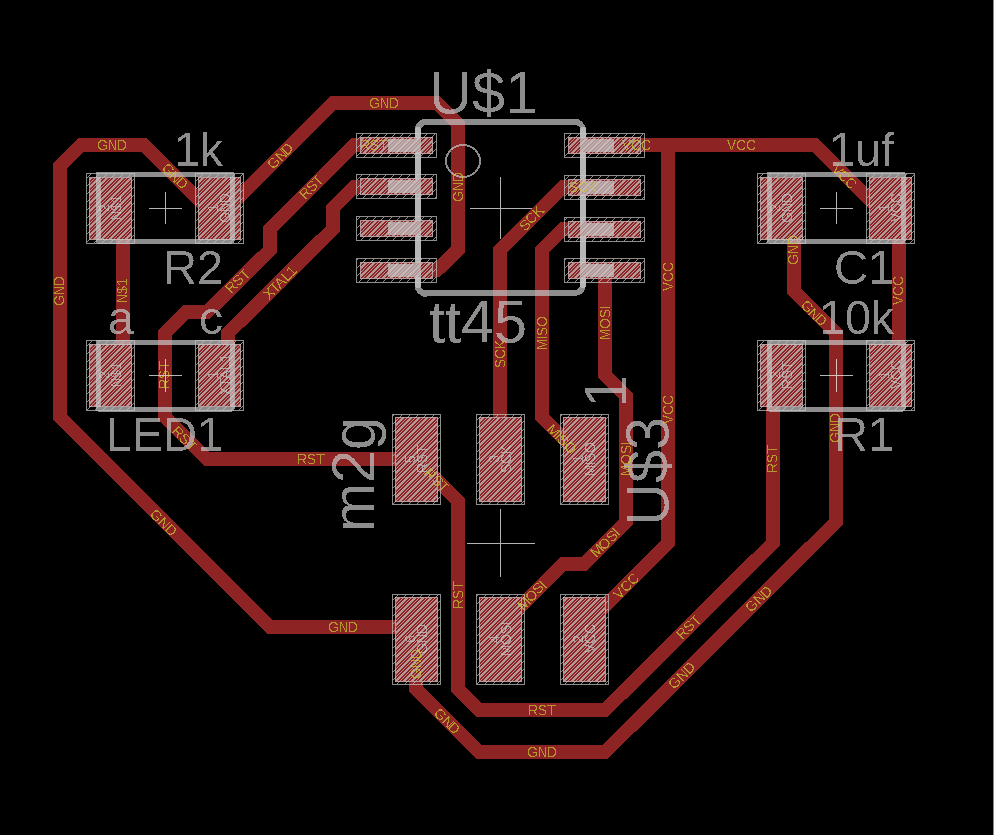
File’s Name in the source folder = week7-small-noftdi.brd
File’s Name in the source folder = week7-small-noftdi.png
Here the 2 node board are connected by wired. VCC of 1 to VCC of other and the same for GND and SCK pins.
Programming & Application
Processign GUI
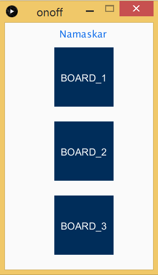
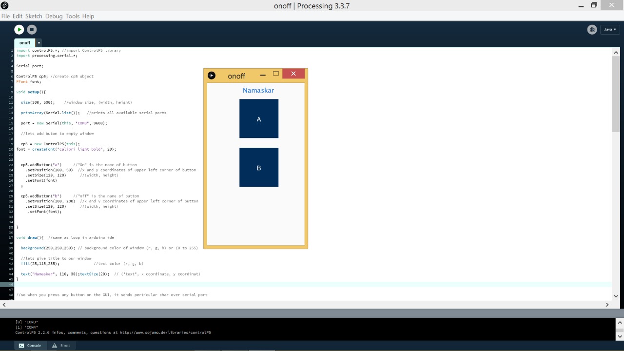
- In the previous week, I controlled LED from an application which I developed on Processing. For this week I have done something similar. I have modified the Processing GUI/application to accommodate control for 3 board. Instead of the On and OFF button there are now Board 1,2&3 buttons which control the LED of the board.
- By pressing a button it sends a character to the serial port which is then compared by the MC for further action.
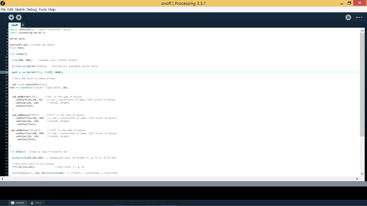
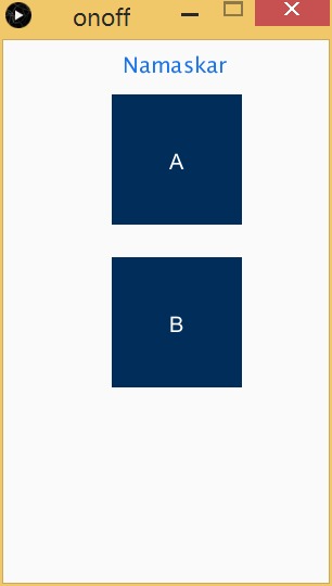
- I Modified the code for 2 Boards since one of my boards stopped working :
import controlP5.*; //import ControlP5 library
import processing.serial.*;

Serial port;

ControlP5 cp5; //create cp5 object
PFont font;

void setup(){

  size(300, 500);    //window size, (width, height)

  printArray(Serial.list());   //prints all available serial ports

  port = new Serial(this, "COM12", 9600);

  //lets add button to empty window

  cp5 = new ControlP5(this);
font = createFont("calibre light bold", 20);


  //cp5.addButton("Board_1")     //"Board 1" is the name of button
  cp5.addButton("A")
    .setPosition(100, 50)  //x and y coordinates of upper left corner of button
    .setSize(120, 120)      //(width, height)
    .setFont(font)
  ;

  //cp5.addButton("Board_2")     //"Board 2" is the name of button
  cp5.addButton("B")
    .setPosition(100, 200)  //x and y coordinates of upper left corner of button
    .setSize(120, 120)      //(width, height)
     .setFont(font);

 //cp5.addButton("Board_3")     //"Board 2" is the name of button
    //.setPosition(100, 350)  //x and y coordinates of upper left corner of button
   // .setSize(120, 120)      //(width, height)
    // .setFont(font);

}

void draw(){  //same as loop in arduino ide

  background(250,250,250); // background color of window (r, g, b) or (0 to 255)

  //lets give title to our window
  fill(25,115,235);               //text color (r, g, b)

  text("Namaskar", 110, 30);textSize(20);  // ("text", x coordinate, y coordinate)
}


//so when you press any button on the GUI, it sends particular char over serial port

void A(){
  port.write('a');
}
void B(){
  port.write('b');
}
//void Board_1(){
//port.write('1');
//}

//void Board_2(){
//port.write('2');
//}

//void Board_3(){
//port.write('3');
//}
- File’s Name in the source folder : processing.pde
Arduino Code
- The code for the MC was also a remixed version of the previous week code.
- Each of the board was given an identity : 1,2 & 3.
In the program, the character received from the application is compared with the characters 1,2,3 for each board.
Given below is the code for one of the Node boards( in this cade, board 3) where input character from serial is compared and commands the LED to turn ON. In the below code, if 3 is received the LED turns on.
I end up using only two board as one of my board’s attiny was burned and i could’t find a replacement.
Board 1 Code
- LED blinks once when character ‘a’ is recieved.
#include <SoftwareSerial.h>
 const byte rxPin = 2;
 const byte txPin= 1;
 SoftwareSerial mySerial =  SoftwareSerial(rxPin, txPin);

// the setup function runs once when you press reset or power the board
void setup() {
  // initialise digital pin 13 as an output.
  pinMode(3, OUTPUT);

    // set the data rate for the SoftwareSerial port
  mySerial.begin(9600);
}

// the loop function runs over and over again forever
void loop() {

//listen to serial port

if (mySerial.read()=='a') // if 'a' is recieved from serial, LED will blink once

for(int x=0; x<1 ; x++) // FOR loop runs thrice, LED blinks once
{
digitalWrite (3,HIGH);
delay (500);
digitalWrite(3,LOW);
delay (500);

}

}
- File’s Name in the source folder : networking_a.ino
Board 2 Code
- LED blinks once when character ‘b’ is recieved.
#include <SoftwareSerial.h>
 const byte rxPin = 2;
 const byte txPin= 1;
 SoftwareSerial mySerial =  SoftwareSerial(rxPin, txPin);

// the setup function runs once when you press reset or power the board
void setup() {
  // initialize digital pin 13 as an output.
  pinMode(3, OUTPUT);
    // set the data rate for the SoftwareSerial port
  mySerial.begin(9600);
}

// the loop function runs over and over again forever
void loop() {

//listen to serial port

if (mySerial.read()=='b') // if 'a' is recieved from serial, LED will blink once

for(int x=0; x<1 ; x++) // FOR loop runs once, LED blinks twice
{
digitalWrite (3,HIGH);
delay (500);
digitalWrite(3,LOW);
delay (500);

}


}
- File’s Name in the source folder : networking_b.ino
Working video
- Controlling boards through Arduino Serial Monitor :
- Controlling boards through Processing Application :