Mechanical & Machine Design - Polar-graph/ Vertical Plotter
Link to group page is here.
For this and the next week we will have to make a machine which is not completely electronics. For the first week we had to make a basic structure and operate it manually and automate the machine next week.
I have been pretty confident this week since making machines involve mechanical designs which are my forte. We started discussing different ideas and concepts of our telegram group.
We have 4 students in the lab and hence only one group. I wanted to make something which involved an x-y gantry like a laser cutter. Cnc plotter etc. because I had previous experience with these kinds machine and they seem cool.
Here are the ideas :
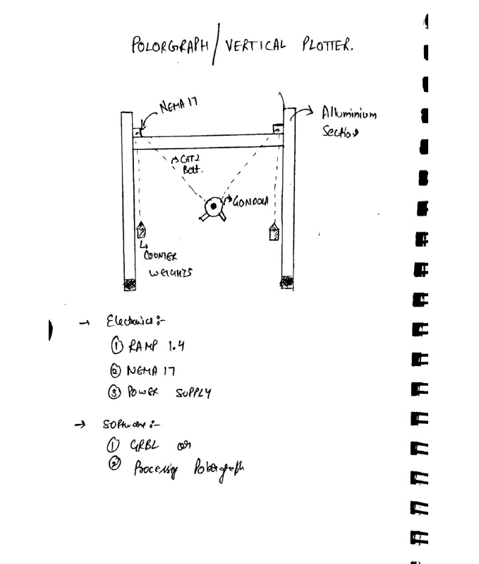
- I wanted to build a Polar-graph/Vertical Plotter.
- Ashish wanted a Coffee Machine with an inbuilt alarm.
- Rahul wanted to recycle the CNC dust by making bricks out of them.
- Vyanetha was Nill.
After some discussion, we decided to make the vertical plotter as it was particularly easy to make within the timeframe. I started the work by searching the internet and getting some ideas.
Here is the initial sketch :
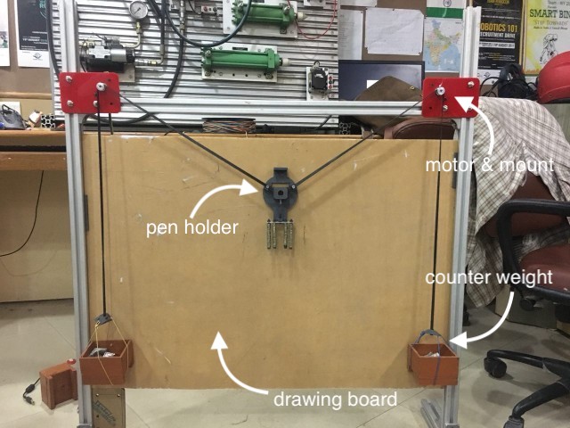
Division of Roles
I was incharge of all the mechanical assembly and manufacturing. I had to get the machine up on it’s feet.
- Built the aluminium frame
- Stepper Motor Mounts
- Counter weight
- Gondola/pen holder
- Drawing Board
- Rahul was incharge of all the electronics, interfacing the stepper motors through RAMPS and controlling it through software.
- Vyanetha was a great helping hand. He did both the mechanical and electronics part.
Vertical Plotter
- The vertical plotter is a kind of printer but different from the conventional inkjet and dot-matrix printers, since it does not print but draws by means of pens,like a person would do with his hand.
- It allows to draw diagrams and sketches of various kinds, which can include text , art ,or anything.
- We are trying to make a low cost vertical plotter, which is achivable by usung cheap steper motors and aluminium extrusions.Also the controller board is an open-source and easilt available at cheap prices ; RAMPS 1.4, It i extensiveely used in hobby DIY 3d printers.
Machine Specification
- Work Area : 45cm X 45 cm
- Motor Specification : NEMA 17
–Inductance per Phase: 23 mH
–Holding Torque: 2000 g-cm
–Detent Torque: 220 g-cm max
–Weight: 0.24 kg (0.5 lbs.)
Machine size : 74.5cm x 64.5cm
Maximum pen diameter : 15mm
The Build
- Our instructor asked us to make the machine fro material completely fabricated in the lab and if not then the next best thing is to use material fro waste. or re-use the material. So for the Aluminium Sections I decided to take apart an old Project, which was made by our college students.
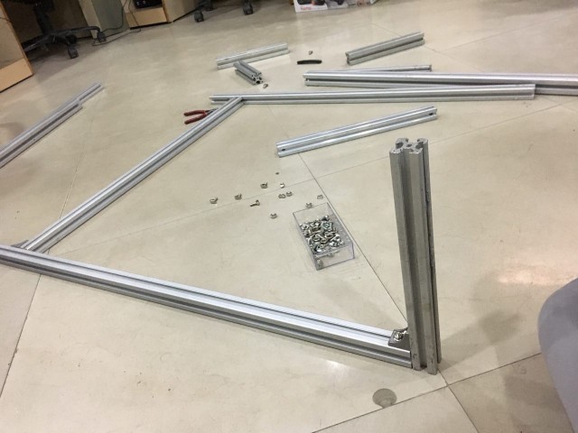
- Material needed for the main frame :
- Aluminium Sections
- T-nuts , Bolts
- Angle
- Material other than the frame :
- Weights x 2
- Nema 17 x 2
- Pulley and Belts.
- Since out lab is established under the college, students of the college participate in different competitions and make many machines for the same. One such machine was lying in the lab, which was around 2 years old. I Decided to take the machine apart as it had all the parts we needed for the frame.
Step -1
Sourcing Parts
Dismantling an old project for a new one. The dismantled project was lying around in the lab for almost a year and we thought it would be best to use the parts from it. It was a winner in Mitsubishi Cup. :
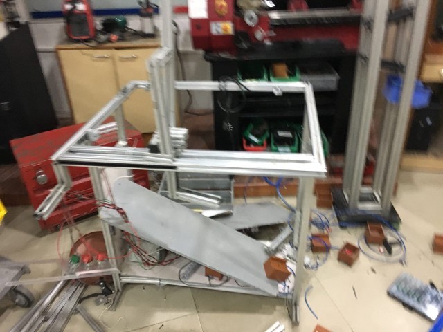
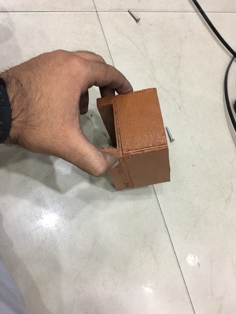
From this project we got the Aluminium Sections and the wooden boxes for counter weight.
Wood Box :
Lending some parts from a Delta 3D printer Project. The parts from the 3D printer were taken on a loan since the person doing the project was not working on it currently: Timing Belt and Pulley.
Step 2
Making The Parts
The leftover parts were 3D printed and laser cut. Not many parts are needed to make the vertical plotter. It’s just about making it as precise as you can. The frame should be squared up, the counter weights should weigh equal, the belt and pulley should engage nice and snug. The motor should not click.
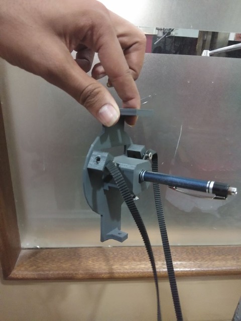
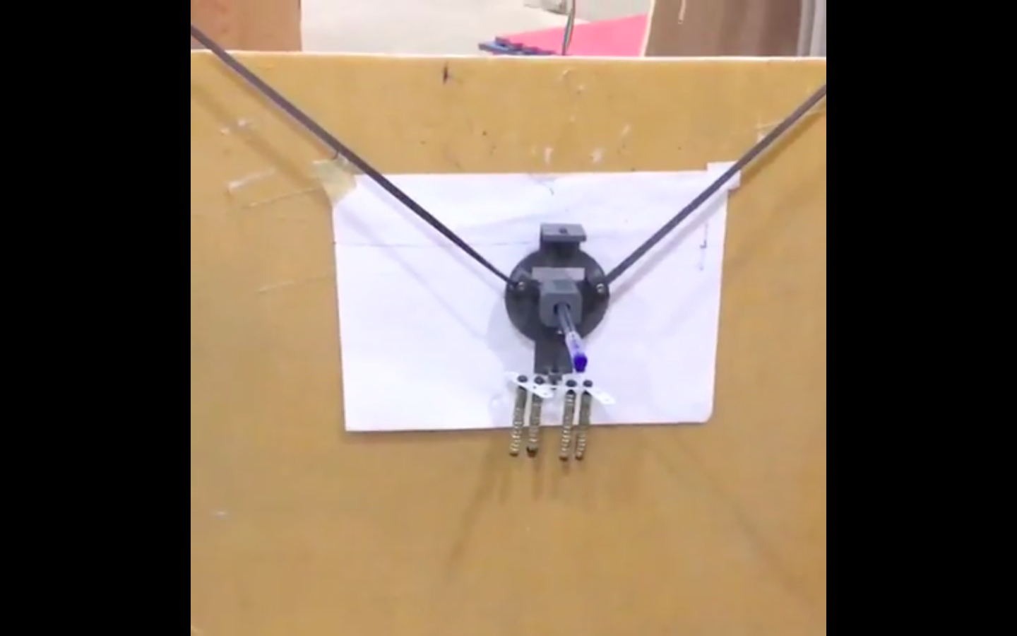
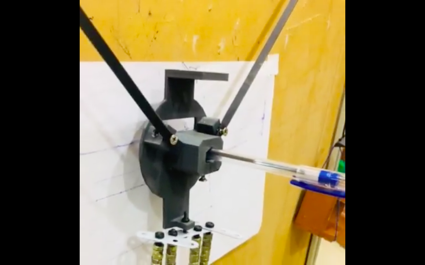
Gondola Pen Holder
- I found a Gondola/Pen holder on thinigiverse and decided to print it. It has a pen holder and a servo motor mount to lift the pen from the drawing board. The penholder has two triangular wings, so to secure it to the belt.
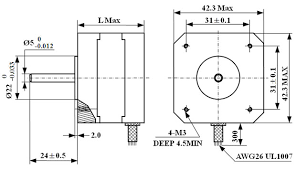
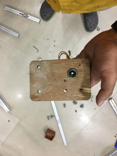
Motor Mounts
- Next step was to mount the motors, I took the dimensions of Nema 17 mounting form the internet and also measure distance from the aluminium sections.
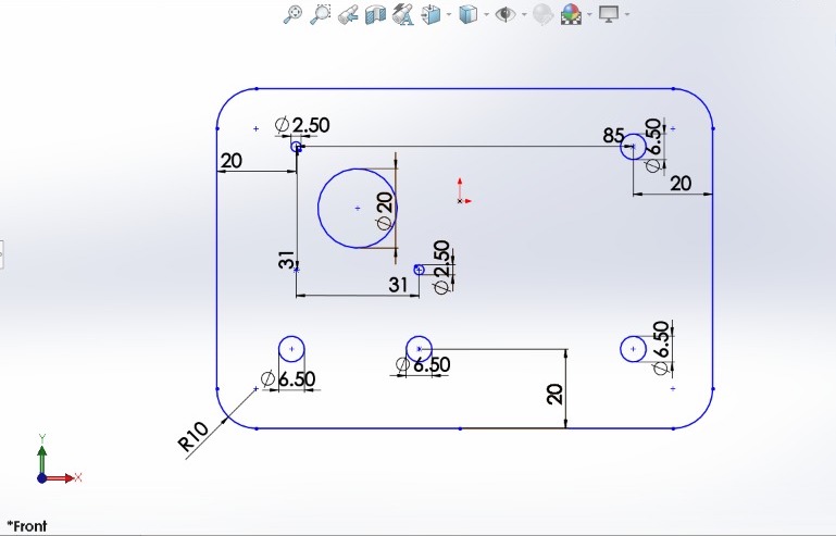
I made a mistake while designing, forgot to make a hole for the shaft. Realised it after laser cutting. I added a hole for the motor shaft in my design and test cut it on a scrap plywood. After i was happy with the fit, I laser cut the final piece of acrylic.
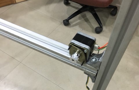
Nema -17 stepper Motor Mount design sketch on solidworks 2016. Most of the veritcal plotters have the motor facing the back side of the machine, I could’t find a concrete reason for this maybe the layout of there machine compelled them to do so. Nevertheless I did’t find that approach right and i decided to mount them facing front on a mounting plate. :
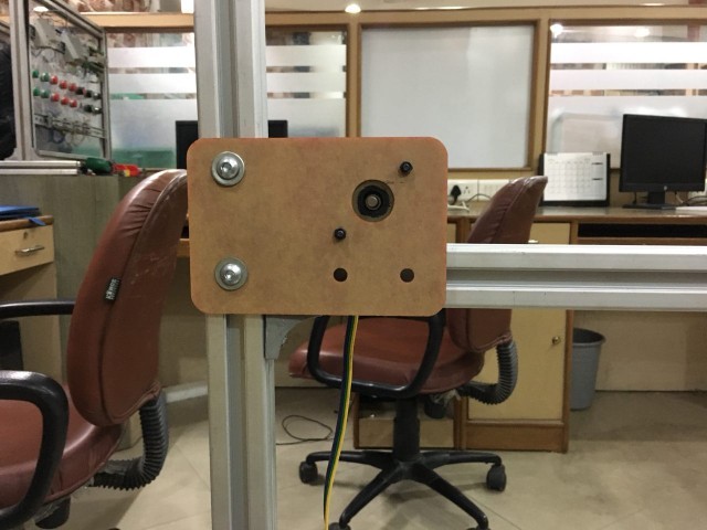
- Here is a test piece i cut on scrap plywood with the motor fitted in it. It worked out perfect hence i decided to cut the final piece in Red acrylic.
- Here is the final piece of acrylic (protective covering is still on). It’s mpunted on the frame with the help of T-bolts. For testng only 2 bolts were fitted.
– Original files here
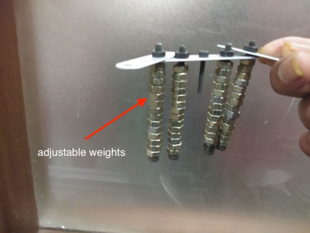
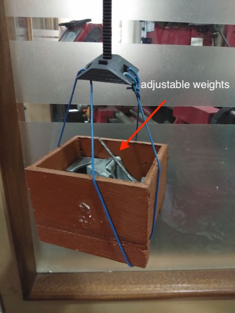
Pen holder Weight
- For the pen holder weight, i took a piece from MECHANIX(a lego like diy kit) and some nuts and bolts. You can use anything as long as it keeps the pen pressed down onto the drawing board.
Function -
The main aim is to press the pen/marker against the board,and bring down the blets tension. The pen holder weght has to be adjsted very carefully, A little less it would not mark the board and a little high it would drag or skip.
The weights have to be adjusted so that the pen holderremains in the right position, even when the machine is not on. Also the weight should be such that they allow the belt to adhere to the pulleys’ teeth.
So make sure the wights you put on the pen holder can be adjusted, like here i’ve used nuts for weight.This way it is easy to calibrate the weights and to choose an adequate number of nuts.
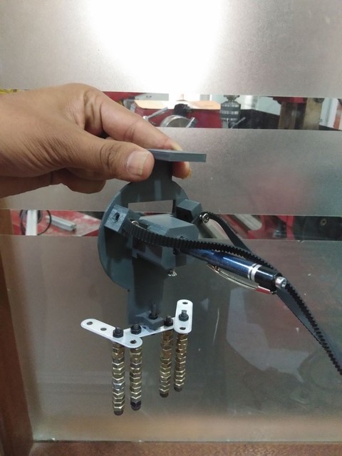
- Weighing assembly mounted on the pen holder.
Counter Weight Coupling
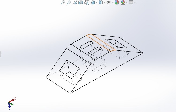
- I sourced the wooden boxes from a previous project, which was sitting in our fablab. To attach these boxes to the GT2 belt we needed a sort of coupling or attachment.
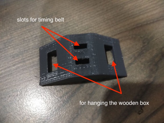
It was a easy fix and a 10 minutes drawing on solidworks 2016. The attachment was 3d printed.
Here also the weight is modular, the wooden boxes can hold items big/small anything. Which helps us to= calibrate the counter weight. Also the wight should be such that the timing belt is just tight.
Heavy weight would make the motor or the belt slip, avoid that.
– Original file here
Drawing Board
- The base for the drawing board was laser cut and fixed into the aluminium section. It was pretty easy, just had to measure the distance b/w the sections and cut the acrylic on laser.
- It’s fixed in the groves of the section.
Step 3
Assembly
After collecting all the stuff me and vyanetha started with the assembly. It was pretty straightforward and easy. Here are some of the pictures..
The main frame was bolted together with cornet or l-brackets and lots of t-nuts. Make sure the frame is square.
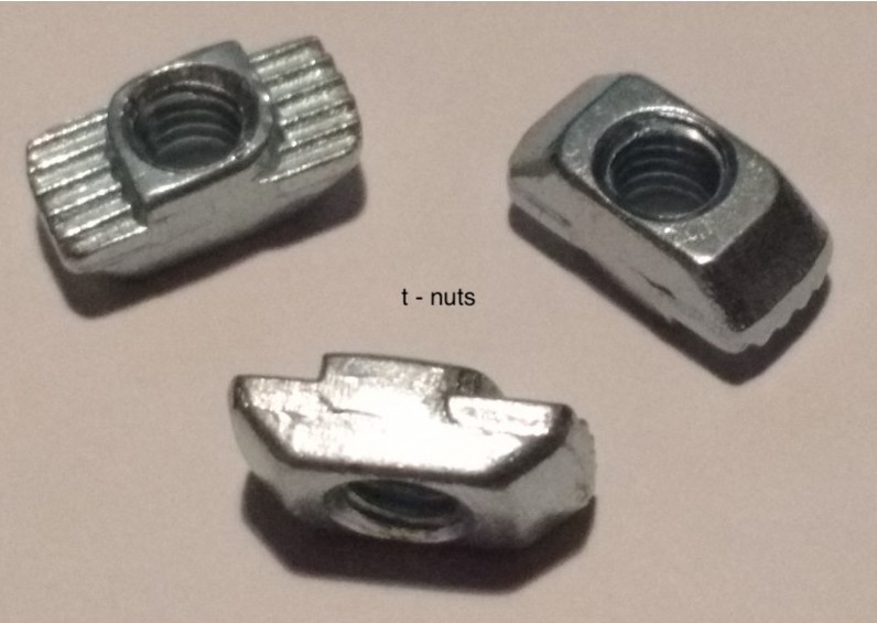
This is how the corner brackets look, you inser bolt into it and screw the t-nut from the other side, only screw half or one thread.
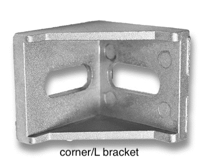
- Now place the t-nut into the extrusion slot and tighten the bolt. repeat with other extrusions.
- This video will help you in assembling the frame beter :
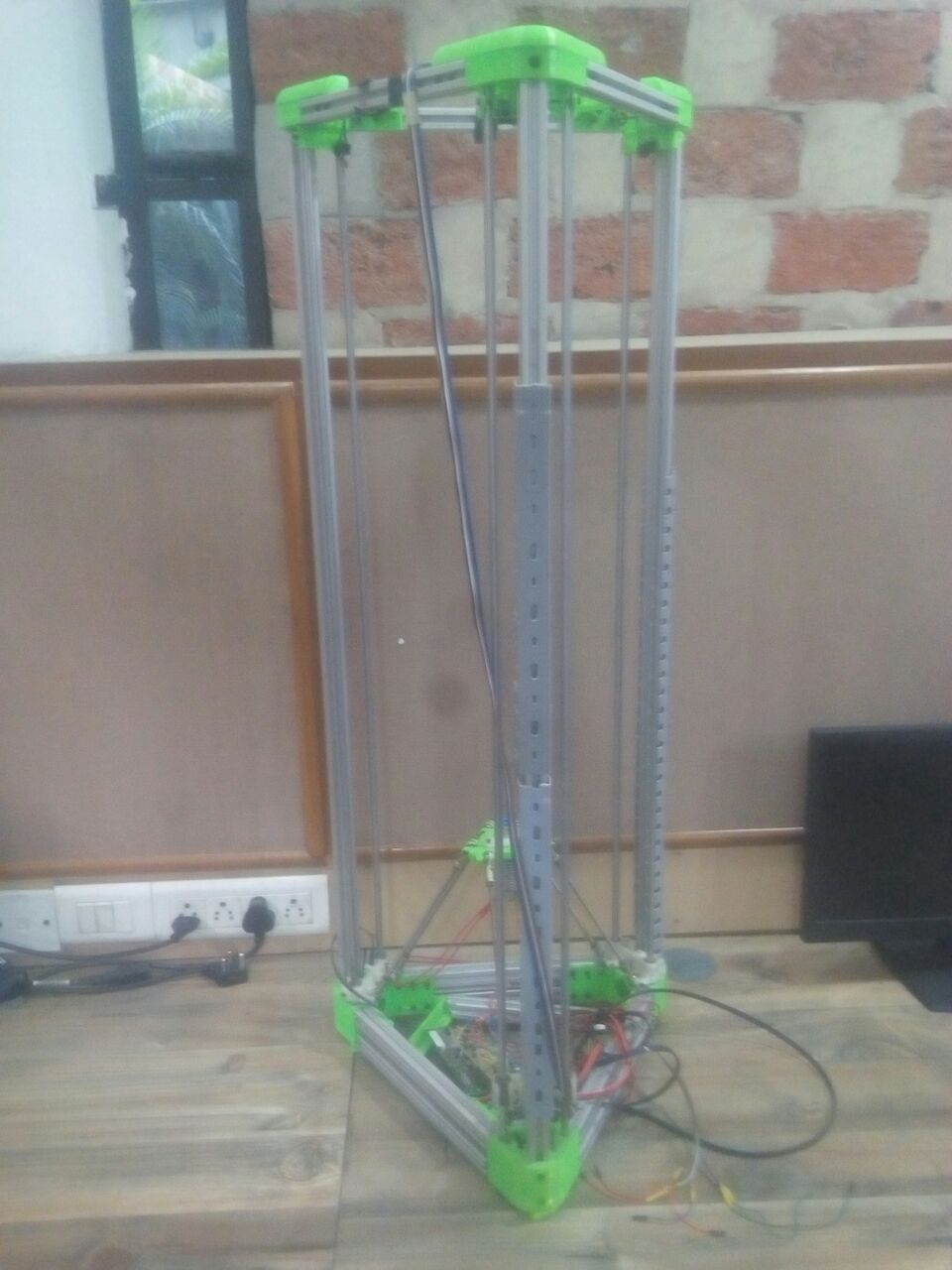
Aluminium extrusions with a square section (side: 27.5 mm); the whole frame is 74.5cm x 64.5cm big,, with a height of 64 cm. horizontal extrusion is 69 cm long, and to the side the vertical extrusions are fixed by means of L Brackets; so the side 27.5mm add up and the horizontal measuremnt is 69cm+ 2.75cm + 2.75cm = 74.5cm.
The frame that we created is not a mandatory solution, one can create it of the prefered size.You have to adjusting the software parameters concerning the print head’s travel. Also you can use a wooden frame made with planks or may directly mount the motors to a wall with some attachement.
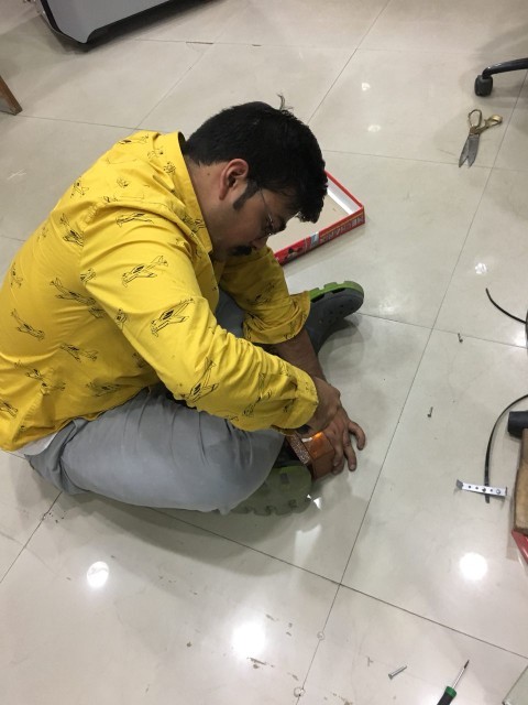
- Here’s a picture of me assembling the frame, can be done by a single person but it’s always better to have a helping hand.
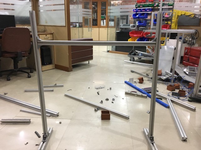
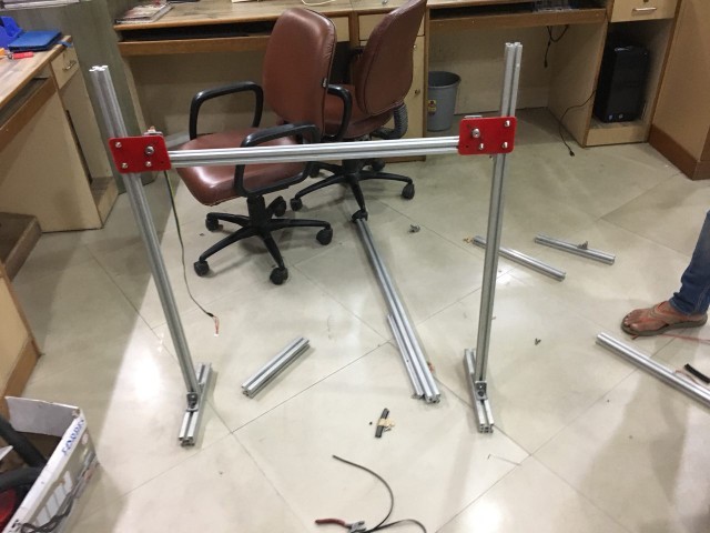
- Here is the finished frame,the horizontal bar which connects the two vertical bars can be moves up and down according to the preference and to callibrate the machine.
- The whole frame is modular in some sorts, if a almunium extrusion doe’st work replace it with a different lenght, have to play aorund. we had a few spare extrusions ad try out different sizes.
Motor Mounts :
- The motor mounts were screwed to the Aluminium sections with the help of t-nuts. Everything was so designed that minimum resources are utilised. So were the mounts.
- 3D printed coupling to hang the wood box from belt. The wire used to hand the box from the coupling also came from scrap. These are PVC electrical wires which are damaged and of no use.
Mechanical Parts done
- For week 15 we had to complete the mechanical assembly and operate the machine by hand. Which we did and it worked perfect.
- The belts are in perfect tension, the weights are equal and the pen is pressed agains the drawing board.
- You can either use the whole drawing are or stick a paper of your choice, we stick a A4 sheet to test the machine by hand.
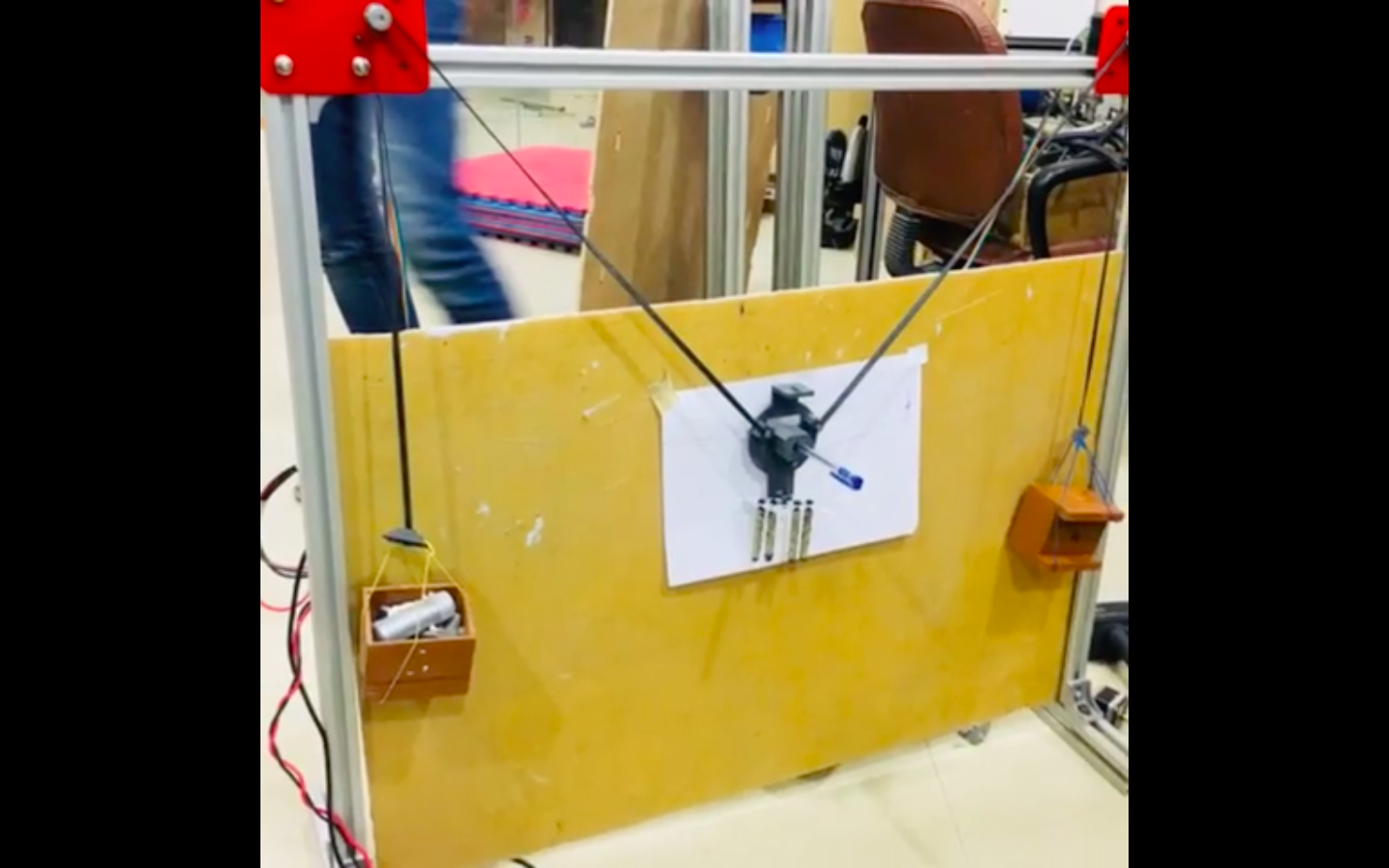
Some test line :
Electronics
- For the electronics, we had to control the two stepper motors to produce the drawings.
- The best way to do the above was to use a RAMPS 1.4 board. It has eough stepper motor drivers needed and works on Arduino Mega which makes ti very easy to programme and control.
- I’ve prevoius experience with a MKS board when I made my 3D printer which is essentially a RAMPS but with Arduino Mega built in.
Stepper Motors
- We used NEMA 17 stepper motors as they are the most widely used in such type of projects, have adequate torque and were also present in the lab.
- Specifications :
–Inductance per Phase: 23 mH
–Holding Torque: 2000 g-cm
–Detent Torque: 220 g-cm max
–Weight: 0.24 kg (0.5 lbs.)
RAMPS 1.4 & Motor Driver
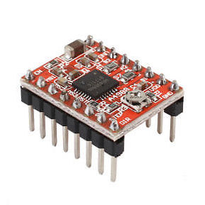
A4988 stpper motor drivers were used to control the motor, these are mounted onto the RAMPS 1.4 board. We needed 2 though ramps can accomodate 4.
This how the driver looks , keep in mind the orientation of the driver befire putting it in RAMPS 1.4 ,
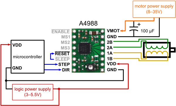
- This is the pinput of A4988 if you are intrested.
- This is how the RAMPS 1.5 looks like, it is essentialy made to controll the 3D printer motors head bed and the hotend. We’ll ne only using it to controll the 2 stepper motors.
- Here i’ve show where the drivers have to be put.
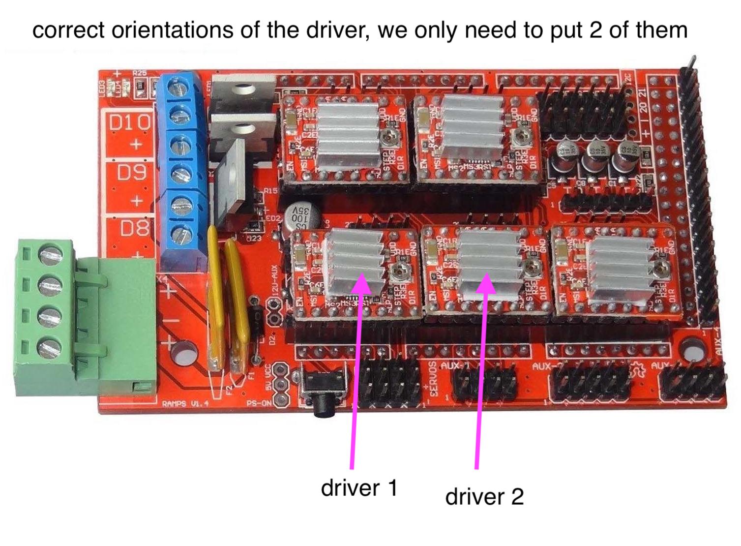
- In the above diagram there are 5 motor drivers, each of them is labelled on the board, X , Y,Z E1 and E2. We only have to put the X and Y drivers,
Firmware
- After trying a couple of firmwares we finally decided to use MAKEANGELO.
- For further explanation on the firware and the elctronics side of the project please visit the group page.