Download all the files for this week from here
For this week I made 2 things :
- A cement planter for my work table.
- Turning a Stop Wall for a machine on CNC Turning.
Cement Planter
The cement planter would need a mould so that cement can be poured in and take the desired shape.
For the mould i decided to 3D print it and use white cement to cast the pot.
Instead of making a negative of silicone , I’ll be directly casting the white cement. Let’s see how it goes.
Mould for Plant :
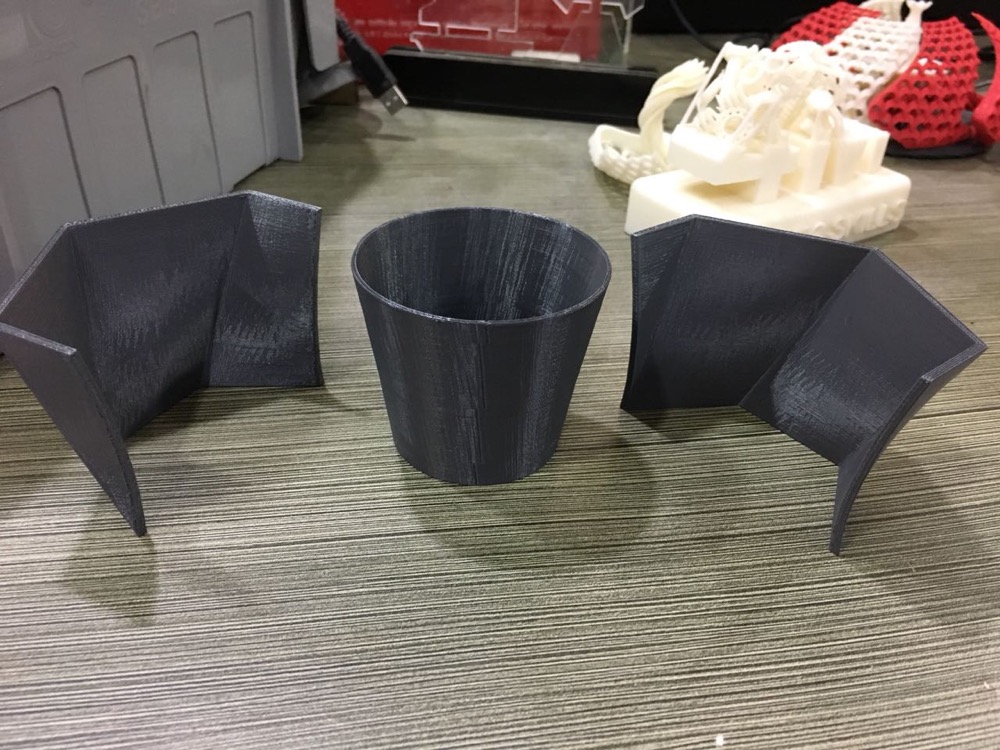
- I started the design on Solidwroks 2016, the mould would be a 2 part so that it can come out easily.
- This was gonna be intresting, as I had low hopes for the mould releasing part.
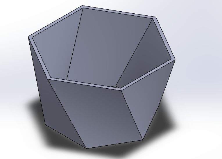
- OUTER MOULD -
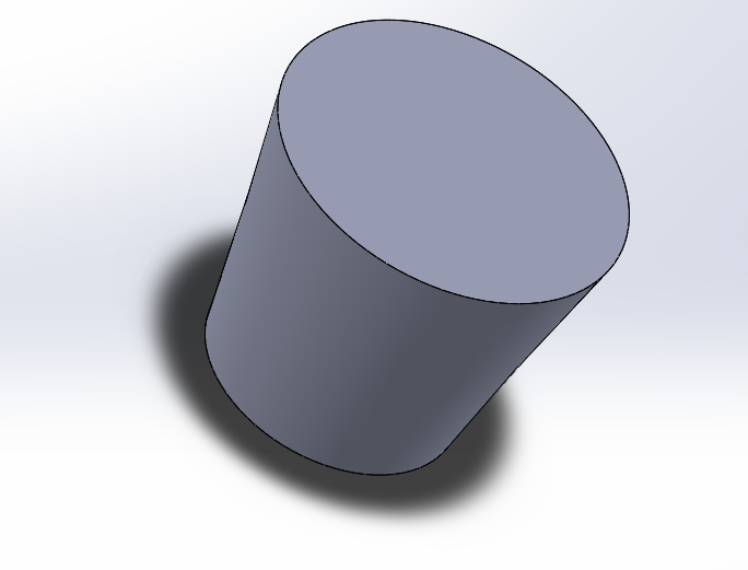
- INNER MOULD -
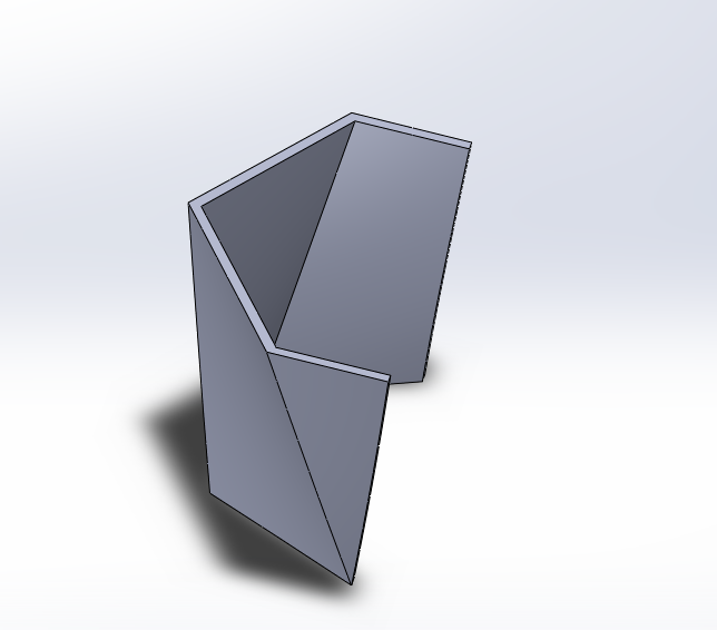
- PARTITION -
Full -
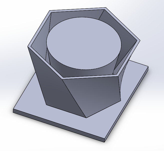
Soldiwork File’s Name in the source folder : mould.SLDPRT
I kept the wall thickess of the outer shell very thin in order to take it apart from the mould easily.
3D Print
I printed the mould on Makerbot Z18, at DRAFT setting.
The model was so designed that it would not need support material.
The outer mould was printed in two parts.
Initially decided to laser cut the base, since it was 2D and would be foolish to 3D print. Later on I skipped the laser cut part and used polystyrene base instead.
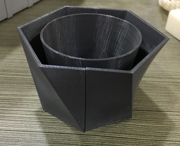
Mould Assembly
- Before putting the mould together, I covered the inside of the walls with tape in order to give a smooth surface and also to prevent cement from creeping in which would also help in releasing the mould.
- Assembling the mould was easy, I used tape to hold it all together.
Casting
- For casting I used White cement. I added ample amount of cement and then started pouring water until I got the right consistency. The consistency should be that of a Pancake Batter.
- Make sure to tap the mould to release the air out.
- I kept some weight on the mould, It helped to bring the cement up to the top and not letting the mold bulge.
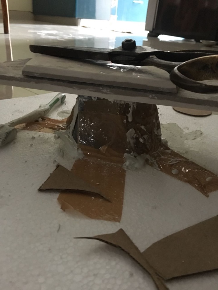
- Since i used tape on the indside of the maould came out very easily.
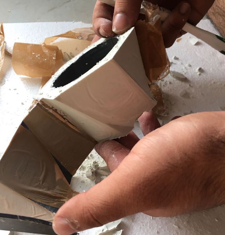
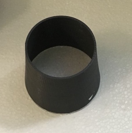
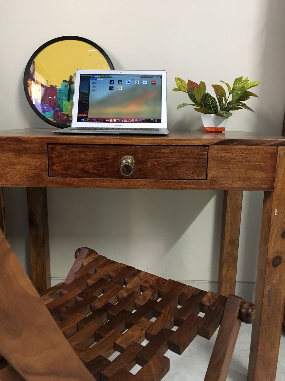
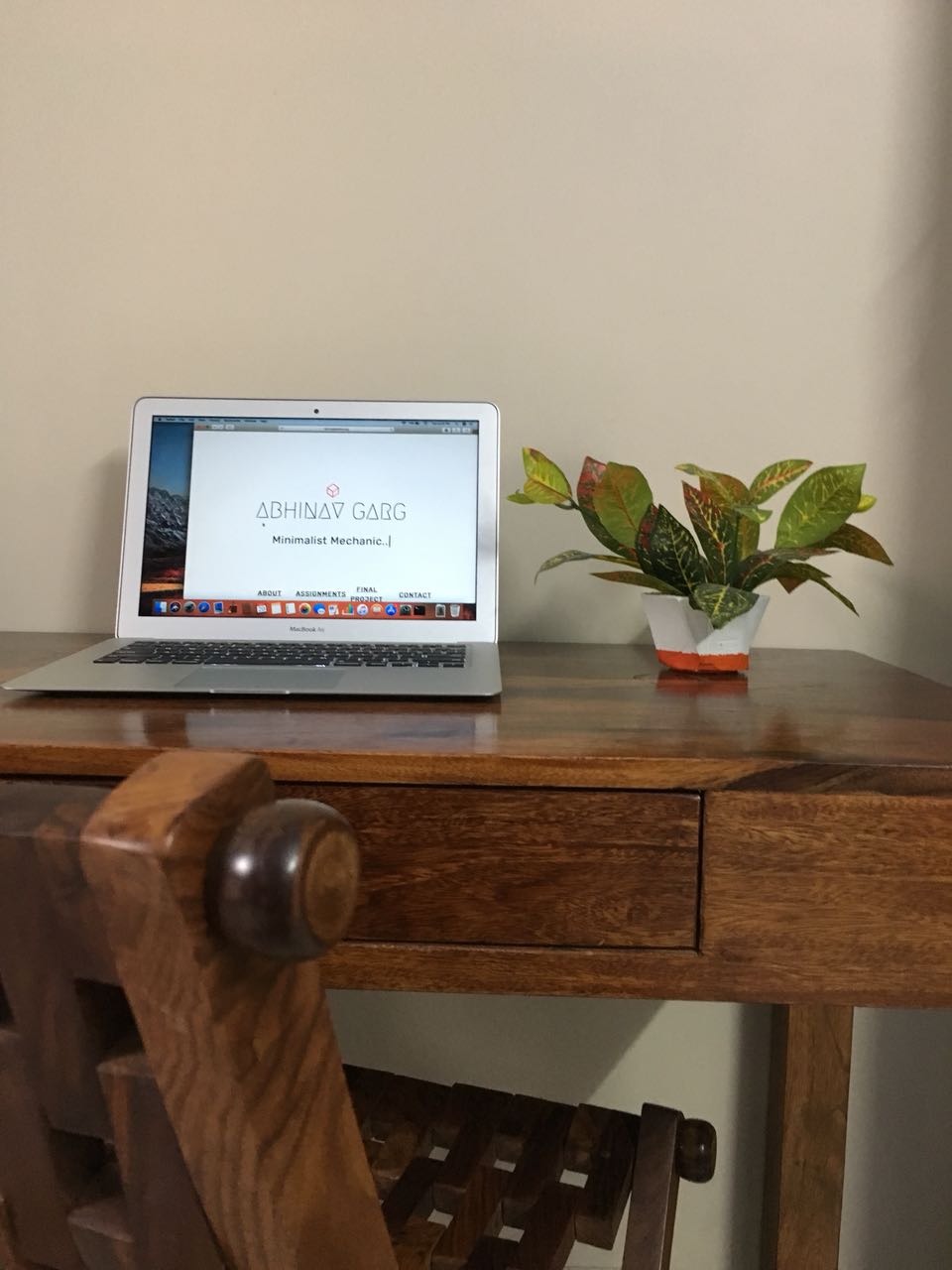
Final Result
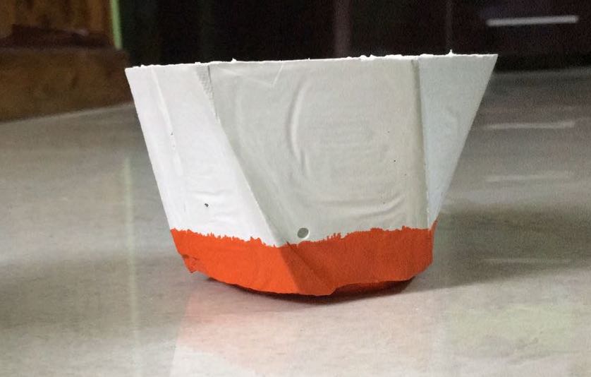
- I was pretty pleased with the final pot, It had some lines from his tape which added to its character. Also, I decided to leave the bottom of the pot unfinished to give it a raw look.
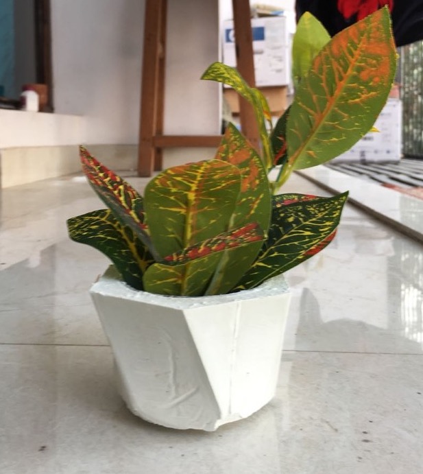
- I painted the bottom orange, don;t know why.
Looks cool on my table.
CNC Turning
- To make sure that i utilise the Wildcard week and provide something which has’t been done in the class I decided to do CNC Turning at one of out college labs.
- Unlike Milling, Turning is a machining process used to make cylindrical parts, where the cutting tool moves in a linear fashion while the workpiece rotates.
Machine Used
- Ace Micromatic LT-16
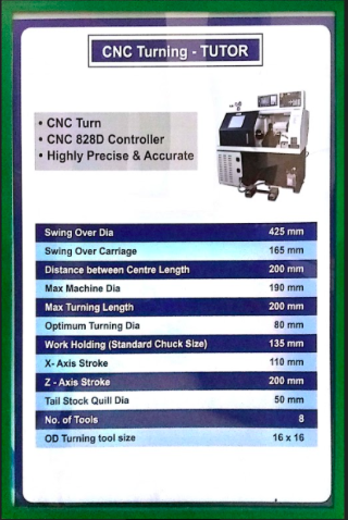
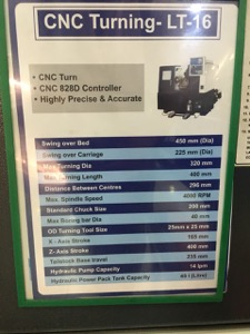
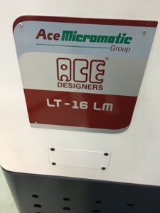
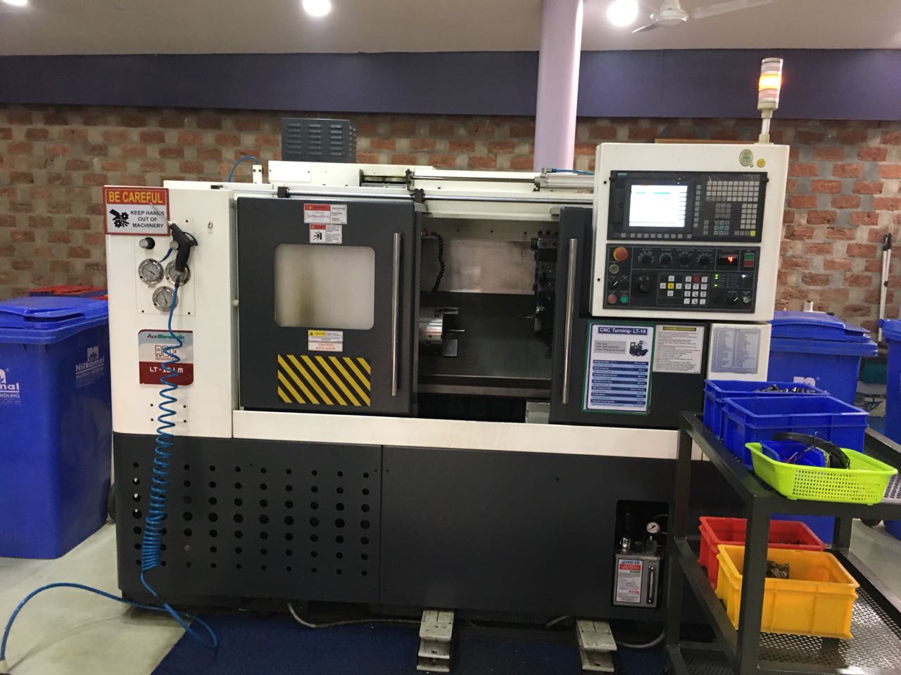
- Controller - Siemens Sinumerik 828D
Tools Used
- Tungaloy CNMG 432-TM Grade T9115 - Turning Insert
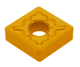
- Technical Spwcifications :
–ANSI Number CNMG 432-TM
–Chip Breaker TM
–Class Turning Insert
–Coating Ti+AL2O3
- Properties and application :
–Turning insert made of cemented carbide PL 10, PVD coated (TiAlN coating)
–For semi-precise cutting of steel, stainless steel, cast iron, nickel and titanium based alloys
–For longitudinal cutting, facing and profiling
CAD
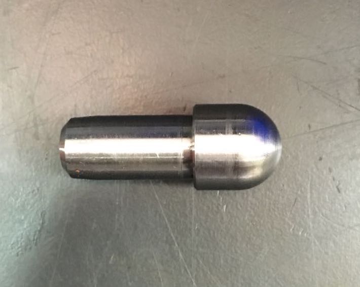
- CAD for the product is very simple , the product to be mnaufactured is a some type of stop valve for a machine. It came to our college workshop for manufacturing.
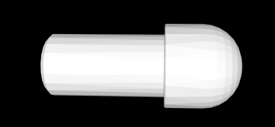
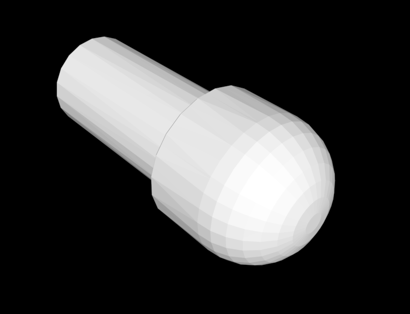
Download the STL file from here.
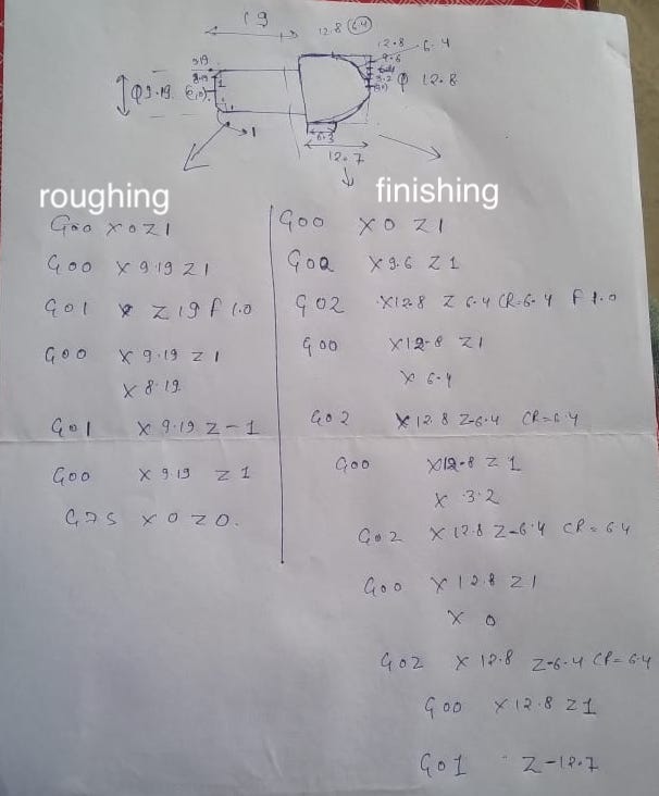
Technical Drawing sheet - 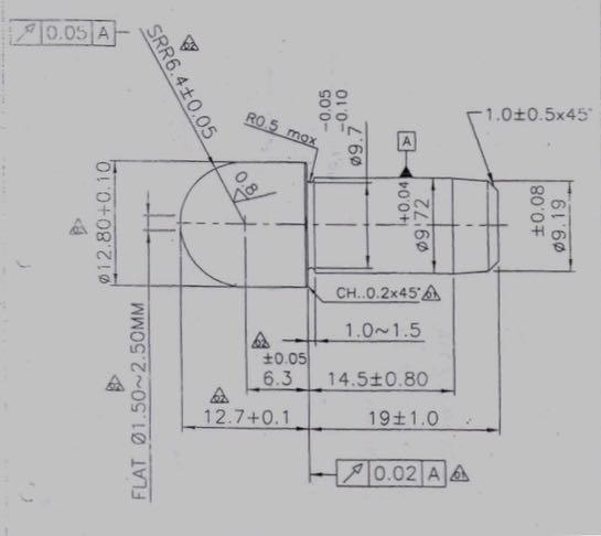
Steps involved in manufacturing
- Job is prepared in two step
First facing operation is done to have the required size then it is followed by step turning and turning operation. This procedure is repeated in twice to gain the required surface finish, so first one is the roughing operation and second one is the finishing operation.
Now second part of job is prepared by facing on the thicker or head side followed by circular interpolation and turning operation. For better surface finish the process is done twice.
Circular interpolation requires five pieces of information’s; an endpoint, a feed rate, a center, a radius, and a direction of movement. Circular interpolation is a motion of tool in circle. It may be a complete circle or less than.
Steps to operate the machine
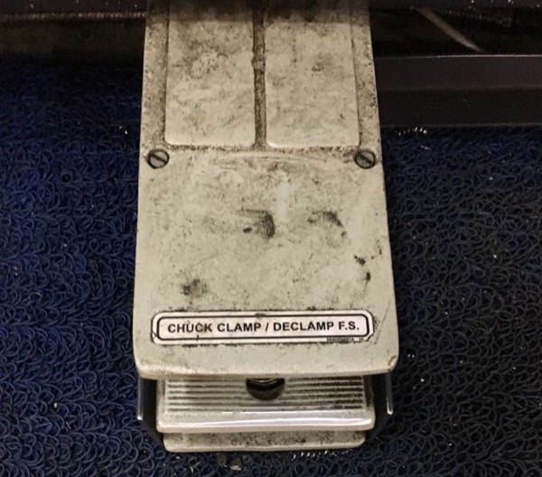
- First, you have to place the job in the chuck. To do so there is a foot pedal which is operated hydralically and opens the JAW of chuck. You can place the job in the chuck and again press the pedal to close the chuck,
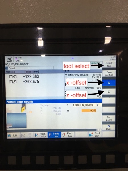
- Then you have to give offset to the tool from the job, first you have to give x offset and then z Offset.
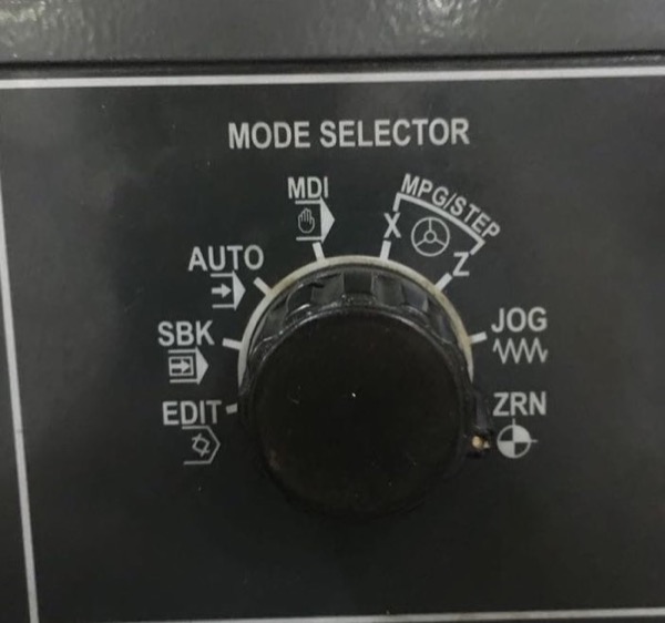
To move the tool, you have to select the jog mode and then using the arrow keys you move around untill you reach the desired psoition.
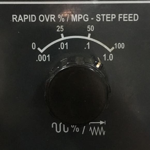
You can aslo choose the jogging speed.
Offsets
- Offsets are given to let the tool know the difference between the workpiece coordinate system and machine coordinate system
- In g codes T1D1 is written for offsets in which D1 is offset value of that particular tool which is already fed to machine
for better understanding on offset go here.
X Offset -
Z Offset -
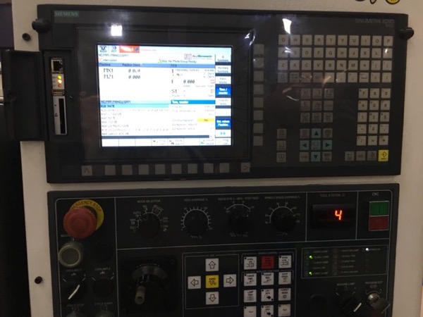
After the offset load the program onto the controller thorugh a pendrive , you can also directly write the program on the controller itself(which i did).
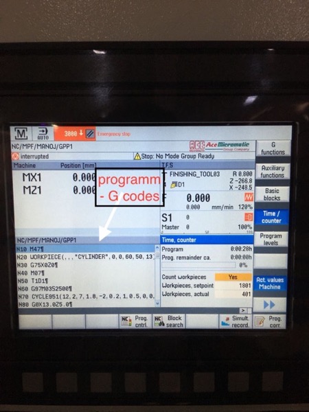
Controller Screen showing the different options and g-code.
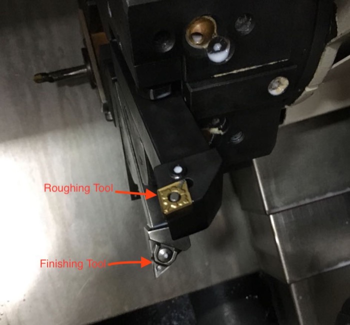
There are 2 processes, Roughing and Finishing. Both the process use different tools which mounted on the toolpost. The toolpost can accomodate upto 6 tools at a time.
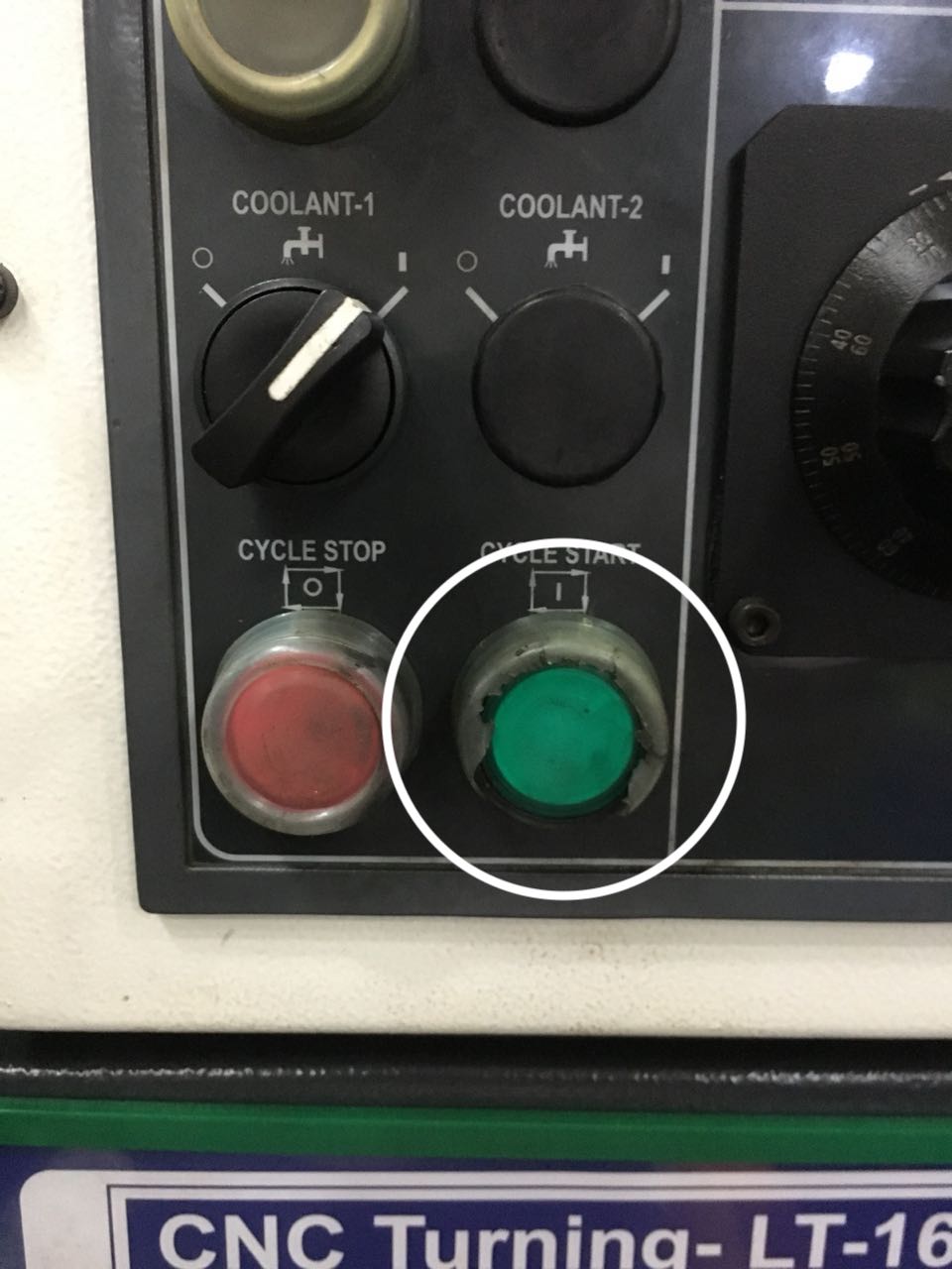
After all the step, hit the button and you are all set to go.
- Video , Not much is seen in the video since the door is closed for machining and white creamy coolent is running.
- Repeat all the steps for the finishing toolpath.
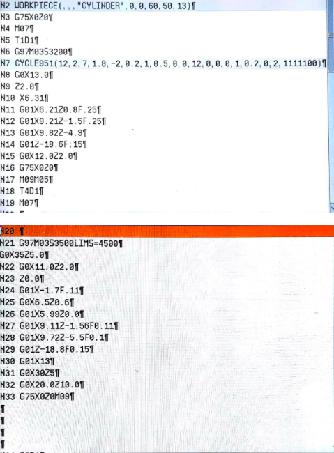
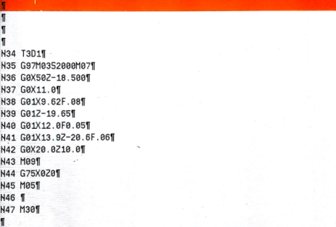
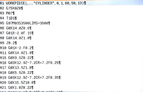
CAM / G - Code
Since the part to be manufactured was simple I wrote the G-coded directly. Alternativey for a Product to be manufactured on the CNC turning, you would give hime the CAD design files which he would put in a CAM software. The CAM software would ultimately give g-codes as output to be fed into the machine. This is the process one would follow for automation.
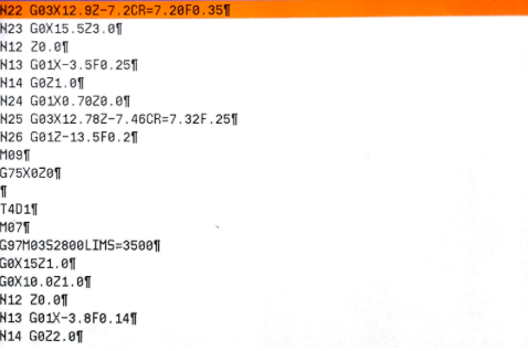
I wrote the program on the CNC controller directly, so I donot have the source file. But I do have my hand written notes and screen captures of the cnc.
The codes are a bit hard to understand , I took help of a friend to write the codes. Thanks Arvind !

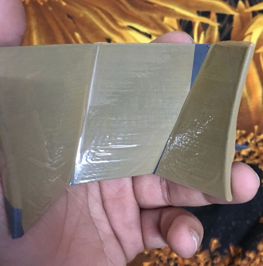
Product
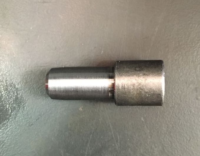
- Initial Stock
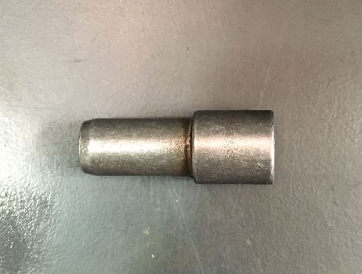
- After Roughing
- After Finishing