I tought i knew it all !
Download all the files for final project cad from here.
I was particularly interested for Week 3 - Computer Aided Design since being a mechanical engineer, I use CAD tools on daily basis hence considered this week to showcase my proficiency in CAD. I use Solidworks for all of my 2D and 3D works and Ansys for simulation.But on Wednesday when Neil was going through all the different software and programs for all the different kinds of CADs I was intrigued. Hence, I decided to start with 2D raster and vector design and left 3D design for later.
1. Vector
I decided to start with vector graphics and for Vector Design I chose INKSCAPE as it is free and can compete with the likes of professional and paid softwares. It is also available for both Ubunut and Windows which I use.
This time I skipped all the written tutorials and the documentations generally provided by the Developer teams and directly watched the YouTube videos. I would recommend watching videos instead of written for graphic softwares as the articles are confusing and half the time you don’t know what you are doing. I found an amazing channel on YouTube - LOGOSBYNICK, the channel has tons of vidoes on Gimps and Inkscape.
Here is a video i used to learn on how to draw a bicycle :
File Name in source folder: cycle.svg
2. Raster
For raster i decied to try my handS on GIMP since it is also free and competitive with paid softwares. I decided to give Fab Academy a thriller,crime look and found the perfect video tutorial on it.
My Gimp Image: 
File Name in source folder: fabthrill.xcf
3. 3D Drawing and Rendering.
As I mentioned above that I use Solidworks for all my 3D drawing and Renderings I decided to showcase my previous work and not to invest any time learning any new 3D softwares. I felt that knowing a single software and having proficiency in that particular software is better than having less proficiency in a bunch of different softwares.But my instructor begs to differ and ultimately convinced me to try and learn a new 3D software, he suggested that I learn OPENSCAD as it uses programming to make 3D and 2D drawings. Well he was right, openscad is so freaking interesting and intuitive.
OPENSCAD
- Above I suggested that one should not read written articles for learning graphic softwares, well in case of Openscad you have to do the opposite of that.I found the documentation of Openscad to be of great help.It is very extensive with examples, codes. images.
I first created a 3x3x3 cube and then re-sized, positioned, change the colors and played with different views. The color option is only for preview not for rendering which I feel was a downside of the software.
Using openscad is all together a different experience as we one writes the codes to generate a 3D model, whereas in softwares like Solidworks it is simply click on the buttons.Then I went on to create another simple 3D shapes like cube, sphere, cylinder etc.! Openscad
The more I spend my time on openscad the more fun it becomes, I found it particularly interesting to create geometrical patterns using transformations and Booleans.Since in upcoming weeks we have Laser cutting and 3D printing I decided to make a part or design for both using openscad.
For 3D printing i decided to create a vase or a pencil stand and for laser cutting i decied to make a geomteric patter which i will convert to dxf.
I would also like to point out that my previous experience with Trubo C++ in school and college helped me to grasp the program quicker.
Vase/Pencil Holder- For 3D Printing :
For a simple vase which broadens upwards we can make it using polyhedral. Polyhedral are the most commonly used 3D object as they are very flexible. Openscad has its own numbering for different corners of a polyhedron. In the images given below both the faces and the corners are numbered.
Faces and Corners of a Polyhedral in OPENSCAD :
Faces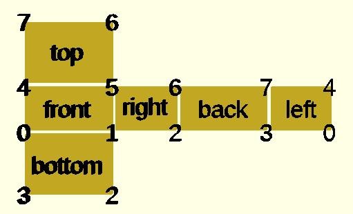 Corners
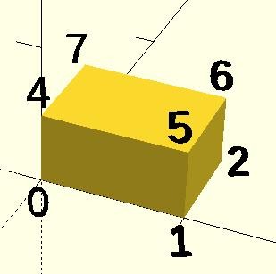
My First attempt :
Code for Above polyhdral(vase) :
CubePoints1 = [
[  0,  0,  0 ],  //0
[ 10,  0,  0 ],  //1
[ 10,  10,  0 ],  //2
[  0,  10,  0 ],  //3
[  -10, -10 ,  20 ],  //4
[ 20, -10 ,  20 ],  //5
[ 20,  20,  20],  //6
[  -10,  20,  20 ]];//7

CubeFaces1 = [
[0,1,2,3],  // bottom
[4,5,1,0],  // front
[7,6,5,4],  // top
[5,6,2,1],  // right
[6,7,3,2],  // back
[7,4,0,3]]; // left

CubePoints2 = [
[  2,  2,  0 ],  //0
[ 8,  2,  0 ],  //1
[ 8,  8,  0 ],  //2
[  2,  8,  0 ],  //3
[  -8, -8 ,  20 ],  //4
[ 18, -8 ,  20],  //5
[18,  18,  20],  //6
[  -8,  18,  20 ]]; //7

CubeFaces2 = [
[0,1,2,3],  // bottom
[4,5,1,0],  // front
[7,6,5,4],  // top
[5,6,2,1],  // right
[6,7,3,2],  // back
7,4,0,3]]; // left
difference(){polyhedron( CubePoints1, CubeFaces1,true );polyhedron( CubePoints2, CubeFaces2,true );}
cube(10,10,1);
File Name in source folder: vase.scad
I wanted something more was like and attractive, something like a swirl. And To achieve the result I had to make the model layer by layer using for loop.
While browsing through the gallery of openscad I found a vase similar to what I wanted, I downloaded the openscad file link> and was presented by a very well written but too complex program for a newbie like me. Still, I tried to understand the program and note down the basic structure of it, which goes:
- Make a cube of a small height.
- Transverse it in the z axis.
- Rotate it every layer.
- After a bit of trial and error the and error the result was satisfactory.
Here is the code for the above drawing :
for (i=[0:200])
{
  for (j=[1:1]) {
    translate([0,0,i])
    rotate([0,0,i*0.8])
    cube([50+i,50+i,1],center=true);
  }
}
File Name in source folder: vase_swirl.scad
As you can see the drawing is not hollow ,hence a simpler code.
Geomtetric Pattern - For Laser Cutting :
For Laser cutting we need a 2D drawing,and to achieve this on openscad i first draw a 3D drawing and then projected it to XY Plane.
Here is the 3D Model :
 Now after projecting the model to XY plane
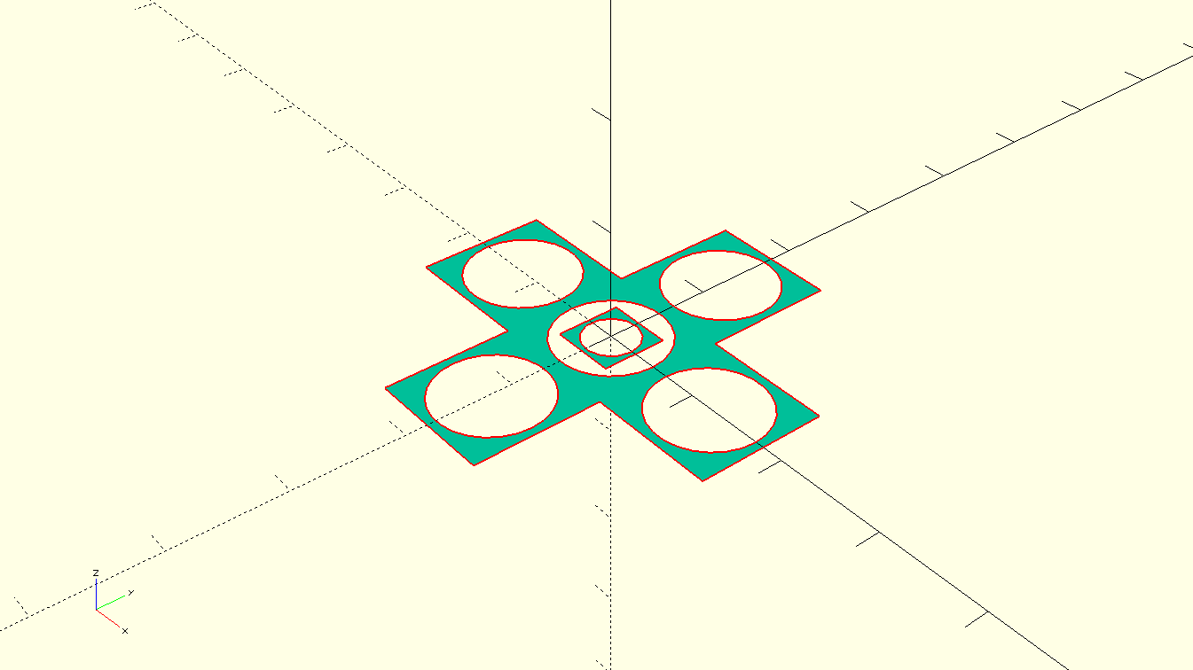
Code for the above pattern :
projection(cut = false) {

difference()  {cube(12, center=true); sphere(8);}
translate([12,0,0]){difference()  {cube(12, center=true); sphere(8);}
}
translate([0,12,0]){difference()  {cube(12, center=true); sphere(8);}
}
translate([-12,0,0]){difference()  {cube(12, center=true); sphere(8);}
}
translate([0,-12,0]){difference()  {cube(12, center=true); sphere(8);}
}
difference()  {cube(6, center=true); sphere(4);}

};
File Name in source folder: geometric_pattern.scad
Solidworks
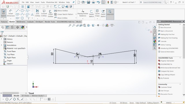
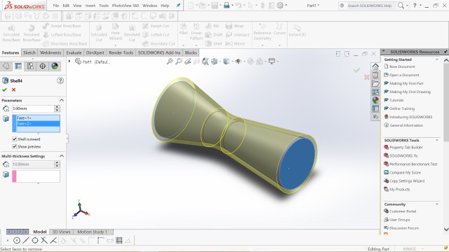
- For the 3D object I designed a De-Laval Nozzle or a CD Venturi. I designed the venturi in Solidworks 2016.
The nozzle has a Converging and a Diverging section. The middle plane where they meet is called the throat. I have provided fillets at the throat for a smooth transition.
Here are some of the screenshots of Solidwokrs :
First start with a 2D deisgn and dimension everything.
- Then use the Rotate command, here you have to selec a axis of rotation and the sketch to be rotated about it.
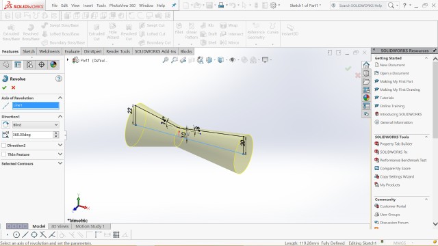
- Use SHELL command to hollow out the venturi.
- After that i just added a flange to mount it and also to provid it a good base for prinitng.
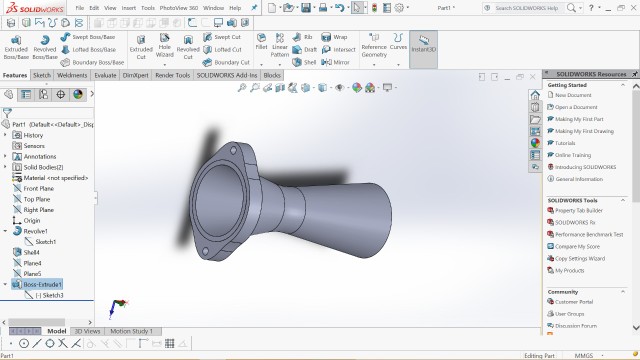
File Name in source folder: venturi.stl & venturi.sldprt
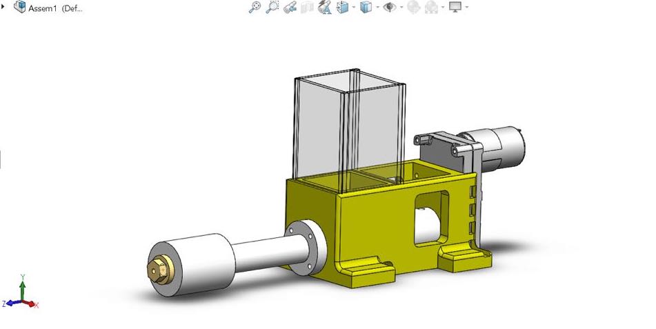
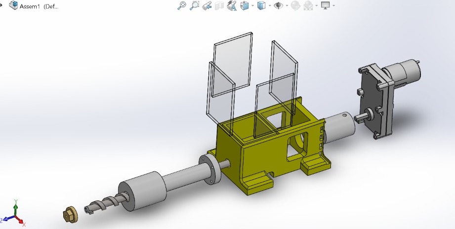
Final Project `CAD
Download all the files for final project cad from here. The files name in the folder is same as the parts mentioned below.
- The CAD for the final project was done on SOLIDWORKS 2016.
- It has the following parts :
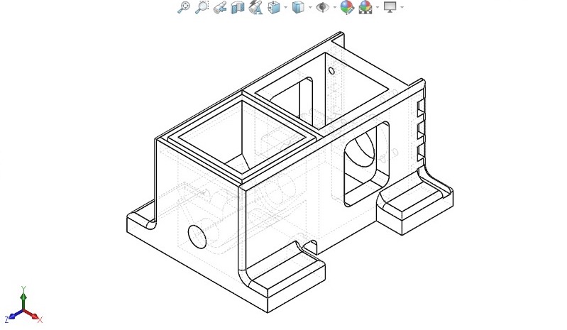
- Base/housing
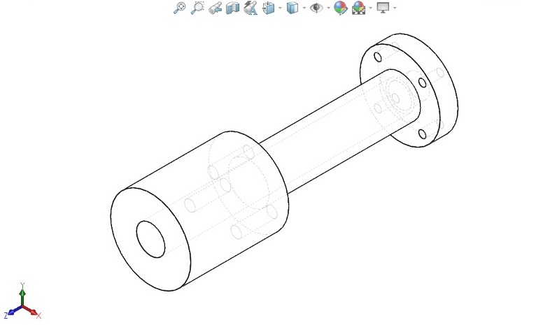
- Barrel
- Nozzle
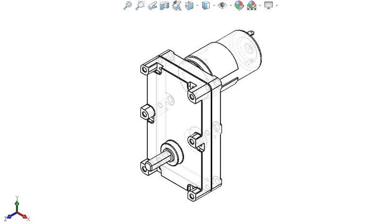
- Motor
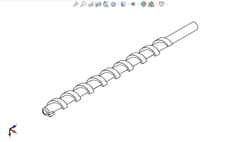
- Auger Bit
Hopper
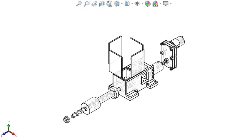
Assembly
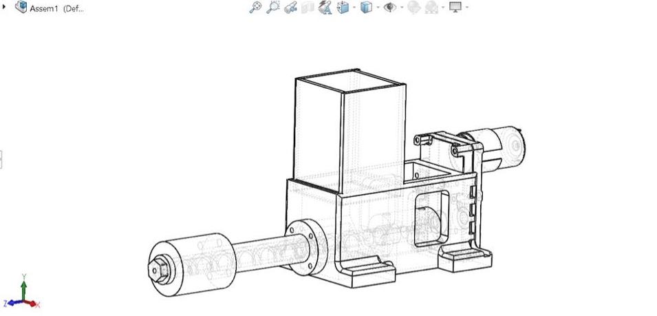
- Exploded View
Barrel
Base/Housing
- Motor
- Auger Bit
Previos Designs
Since I have used Solidworks before and most of my projects are designed in solidworks, i decided to upload my previous designs for showcase.
This design is of Efficyce 2017 which is a competiton held in India organised by SAE-NIS India where teams have to build a hybrid trike. I was the captain of the team and we finished second in the gradebility award. For more on this kindly visit this Link
 Efficycle 2017
This is a Engine Air intake i designed and 3D printed for another competition called SUPRA which is organised by SAE India. I also did CFD analysys on Fluent by Altair Hyperworks.For more on this kindly visit this link. The throttle body is taken fro GrabCad.
Thanks !