Cut It.
Download all the files for this week from here
- For group assignment visit here.
This week where we use machines and get are hand’s dirty. Following are the machines I’ve used this week :
- Vinyl Plotter (Graphtec)
- Laser Cutter (OEM Chinese)
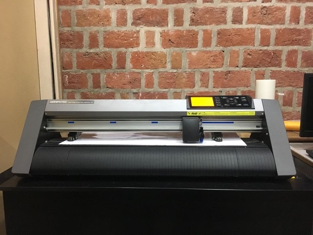
Vinyl Plotter
I started with the Vinyl Plotter,our instructor introduced us to the machines, how it works and the software to interact with the vinyl plotter.
First you load the material you want to cut, in my case it was vinyl sheet. There are two rollers b/w which the sheet is fed. Make sure the upper roller meets the lower roller where the surface is rough so that they can hold the vinyl better.
In our lab we had nothing but different colors of vinyl for cutting, so i decide to cut some stickers and screen print from the stencils.
Vinyl Plotter - Graphtec CE6000-60
Software used - Graphtec Studio
Steps For cutting the Vinyl :
- Import the desired image in the software(any format would do,high resolution preferred).
- Adjust the size of the image by dragging the cursor.
- Click the Trace Option from the upper right, here there are 3 options A. Trace Outer Edge B. Trace
- Set the origin on the machine.
- Connect the plotter and click SEND TO CUTTER.
- The machine should the cut the required files , after that take the masking tape and peel of the sticker with the help of the masking tape. A knife would come in handy.
- Original image from JUNGLEE.COM, a now defunct sister website of Amazon.com .

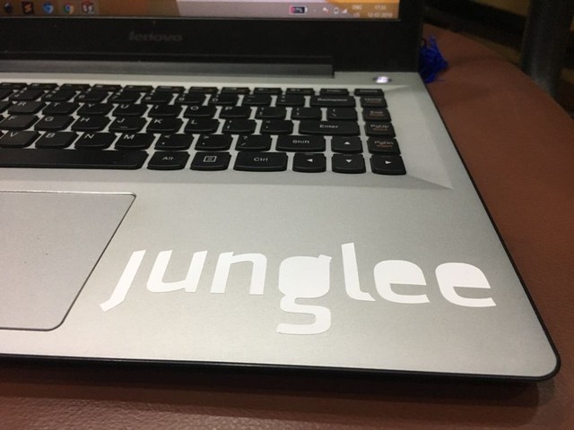
FILES Name in the source folder : Junglee
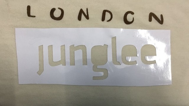
T-shirt print
For t-shirt print i used the outer stencil of the same sticker i cut above. The processed is pretty straight forward.
- Flatten the t-shirt and insert a cardboard or a notebook b/w it.
Paste the stencil on the flatten sticker ,make sure it does’t have any wrinkles.
Use acrylic or fabric paint to paint the letters inside the stencil, do not use water to dilute the paint.
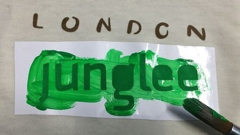
Let it dry for about 10 minutes. Do Not Blow Dry.
Voila, your custom t-shirt is ready bro.
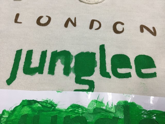
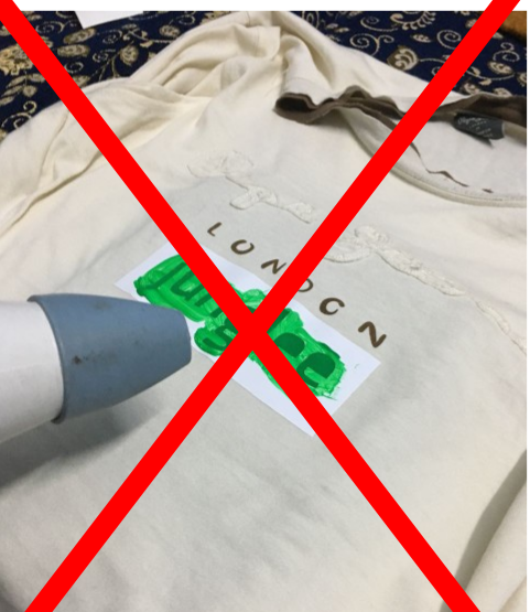
I diluted the paint a little with water and then blow dried it, which resulted in forcing the water outside and ruining the print. for the second time neither did i dilute the paint nor i blow dried the print and the result were better though the condition of stencil was not as good as in the first which caused in bleeding of the paint.
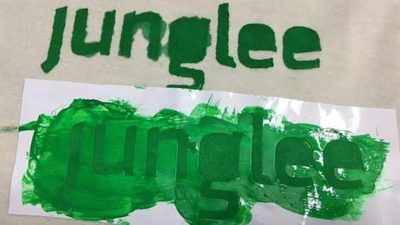
Tried again without blow dry.
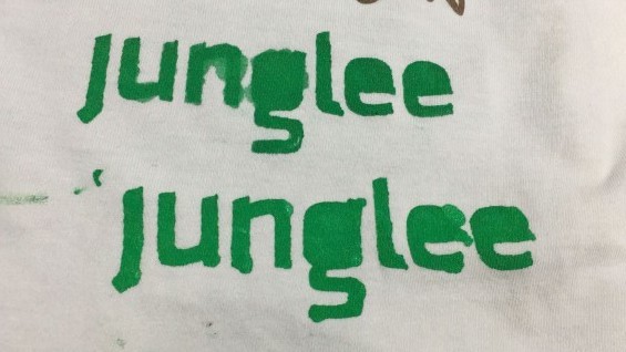 ‘G’ & ‘N’ came out better in the second while ‘E’ were better in the first. I could’t get best of both the worlds.
Laser Cutter
For laser cutter, I used RDworks, it’s very easy to use and also there are some really helpful tutorials on the net to get you started.
First thing was to configure the laser cutter and get the optimum setting,To do that I decided to do a series of test cut by changing one parameters keeping the other constant. And repeating the steps for different parameter.
In a laser cutter, there are mainly two processes you can do :
-Engrave
-Cut
Finding the optimum speed for Engraving & Cutting :
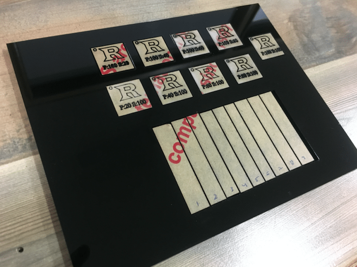
In RD works, there three options :cut,scan,pen and dot. The ScAn option RDworks, I drew 10 rectangles and layered them differently with different power but same speed. I did’t get the required result, then i changed the Speed with same power. Eventually the optimum Power and Speed Combination for Cardboard and 4mm Acrylic was achieved.
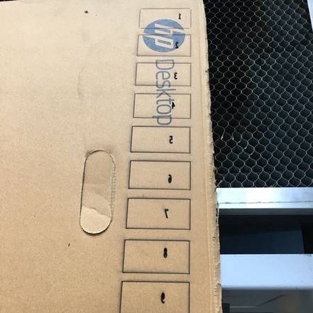
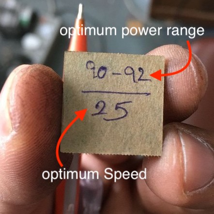
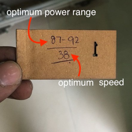
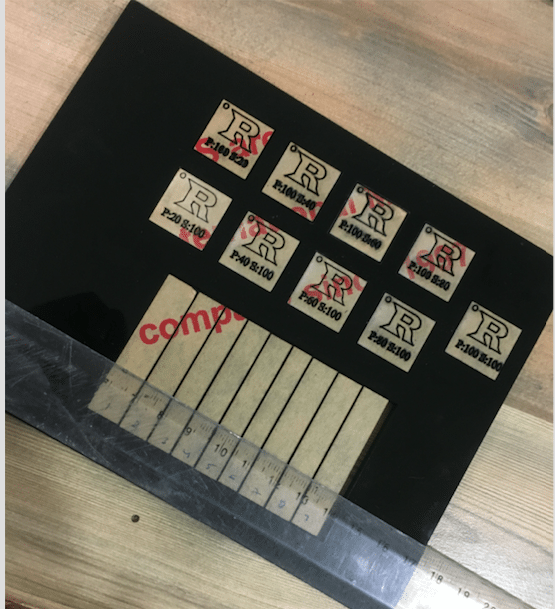
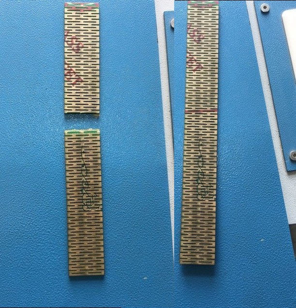
Test Cuts on cardboard and acrylic :
* here I have written the optimum speed and power range to be used for cardboard and acrylic. These test tabs are kept at the laser cutter for future reference.
FILES for test cut were drawn on RD Works Directly
Measuring KERF.
For Measuring the KERF we made 10 cuts within a rectangle. After cutting we shifted all the cut rectangle to one side and measured the gap. Divide the gap by 10, the final obtained value is the KERF of the laser cutter we are using, which is in our case is : 0.3mm
Distance after shifting the cuts = 3 mm. Total number of cuts = 10. So 3⁄10 = 0.3mm which is the KERF of the LASER.
Pictures taken from a fellow student.
Finding what to cut/make on laser cutter :
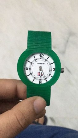
This is the hardest part of the whole assignment, I spend much time surfing the net and going through various videos of various people cutting various things in the laser. And then it struck me, i want to cut something which know one has cut or made on the laser , i found just that- A LASER CUT WRIST WATCH.
I started with taking apart my old wrist watch to find out the part i have to fabricate.
GIF :
Since the strap has to be flexible it need to have live hinges. During the Wednesday lecture one of the fablab members pointed out an extension for living hinges in inkscape. It proved to be very helpful and made the process of designing the living hinges 10 times easier.
Inkscape File with living Hinges :
FILES Name in the source folder : inkscape_file.svg
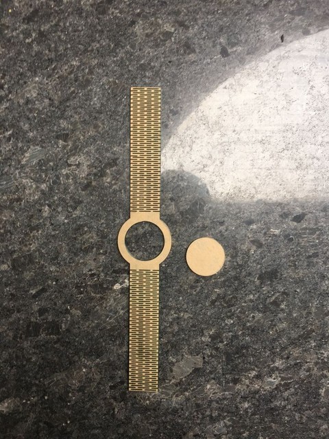
Then I exported the file in solidworks to edit the sketch further more. I added the Dial and the hex-nut slots ,also i deleted some hinges.
SolidWorks Sketch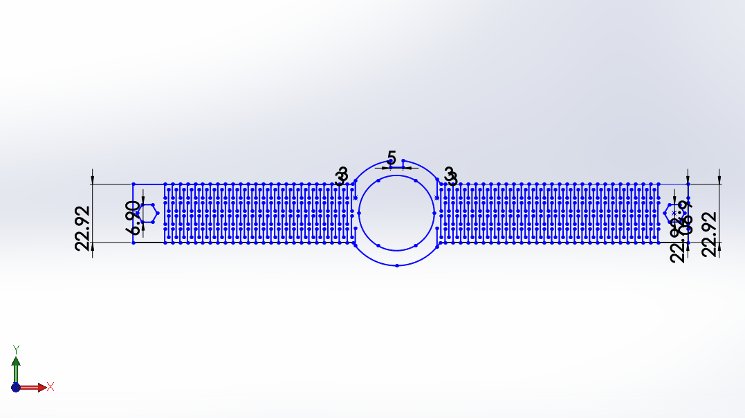 FILE Name in the source folder : Watch.sldprt
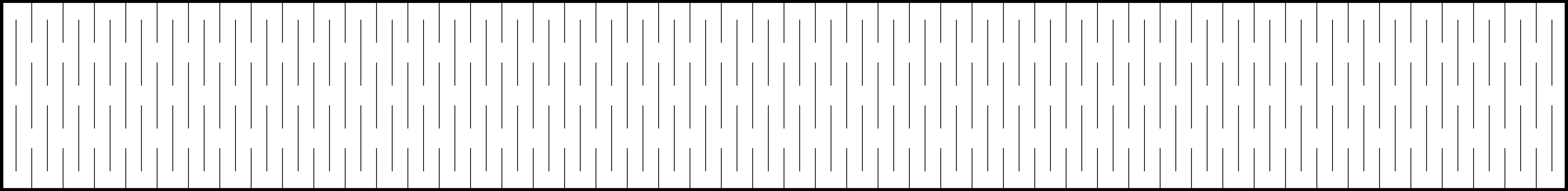
I first cut some samples of live hinges for the strap until i found the perfect one.
Sample live hinges
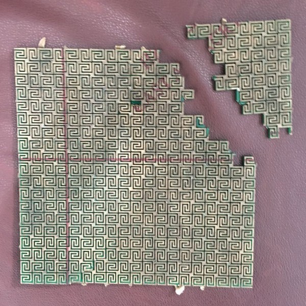
Then i decided to cut the watch strap with the perfect live hinge pattern. I used turpentine oil to remove the protective layer of the acrylic. It bend like a watch but to a certain extent.
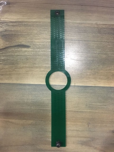

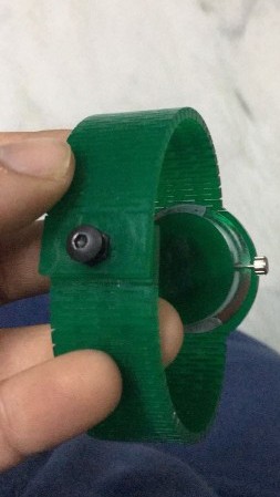
Cutting the strap of watch was relatively the easy part, know i had to come up with a locking mechanism, after some brainstorming i decided to use hex nuts and bolts to lock the watch.
GIF : :
It works fine, fine.
Press Fit - Parametric Kit
- The assignment for this week was long due as i was not able to decide what to make.
At last i decided to make a Track and a Car using sewing machine bobbin.
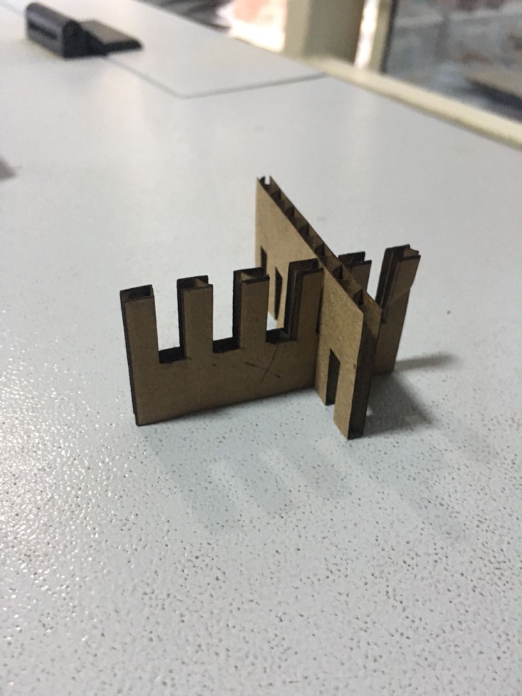
Before Designing I made a Comb like Test piece to check the interference b/w the 2 cardboards and select the best gap thickness.
I used cardboard from Makerboat Filament Box, the thickness of the cardboard was 3.8mm . According to the thickness i designed the comb with 3.8mm to 3mm slot thickness.
A thickness of 3.4mm fir the slots worked best for me.
FILE Name in the source folder : combcardboard.SLDPRT
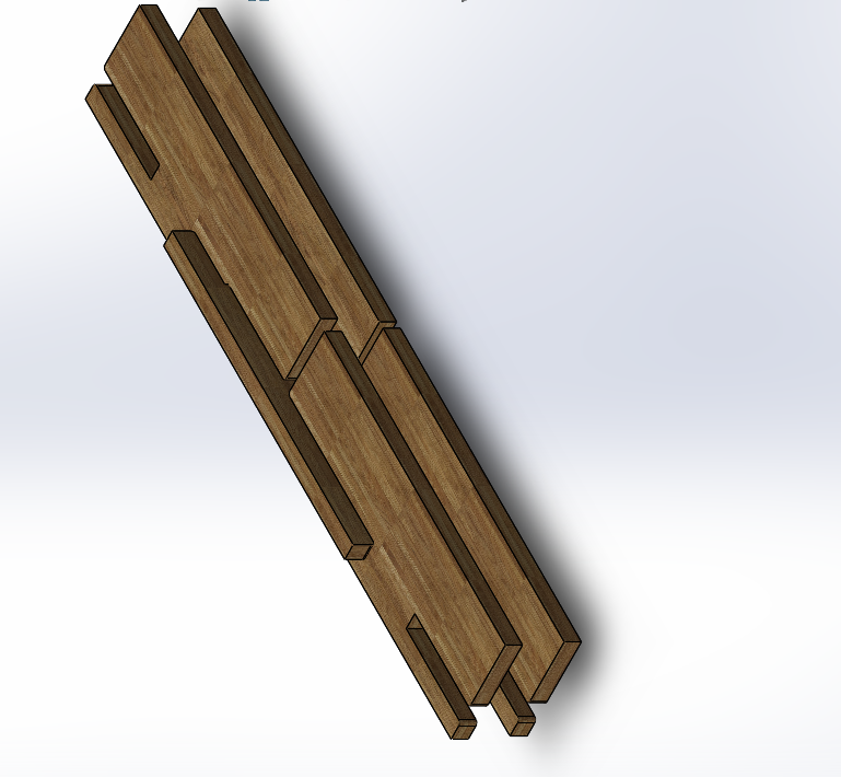
Track
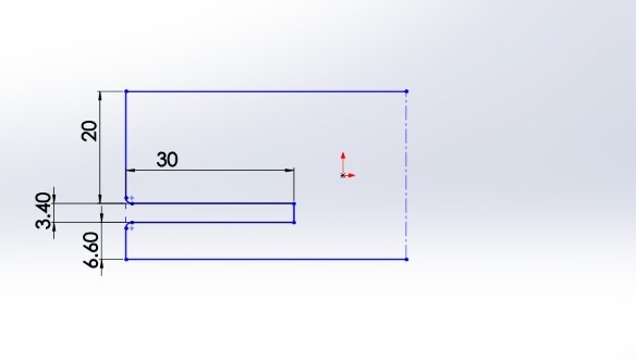
- For the Track, I designed Base and Side Walls on solidworks 2016.
BASE -
- Step -1 Draw Initial Sketch, which is originally 1⁄4 part of the final sketch.
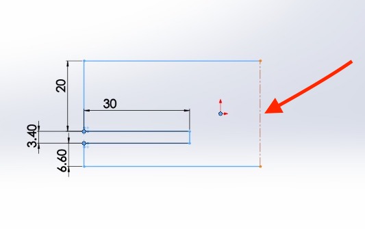
- Step - 2 Mirror about this line, now we have 1⁄2 part done.
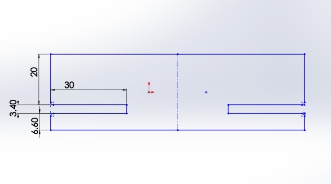
- Step - 3 Again mirror about the mentioned line!
- Step - 4 Complete Drawing.
- Now because of the mirror feature when you change the slot thickness of any other parameter the same is reflected in the change of dimension in the other mirrored slot features.
FILE Name in the source folder :base.SLDPRT
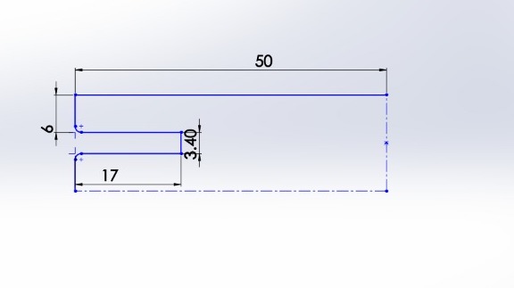
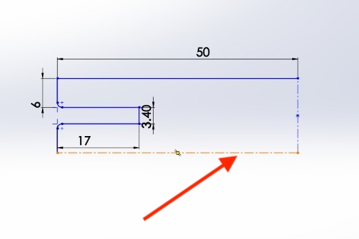
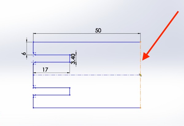
SIDE WALLS -
- Step 1 - Draw the initial sketch which 1⁄2 part of the final
- Step 2 - Mirror it about the mentioned line.
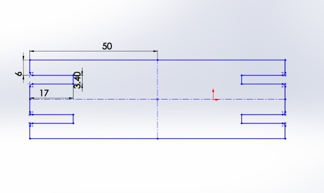
- Step 3 - Final Drawing.
- Now Because of the mirror feature when you change the slot thickness of any other parameter the same is reflected in the change of dimension in the other mirrored slot features.
Laser Cut -
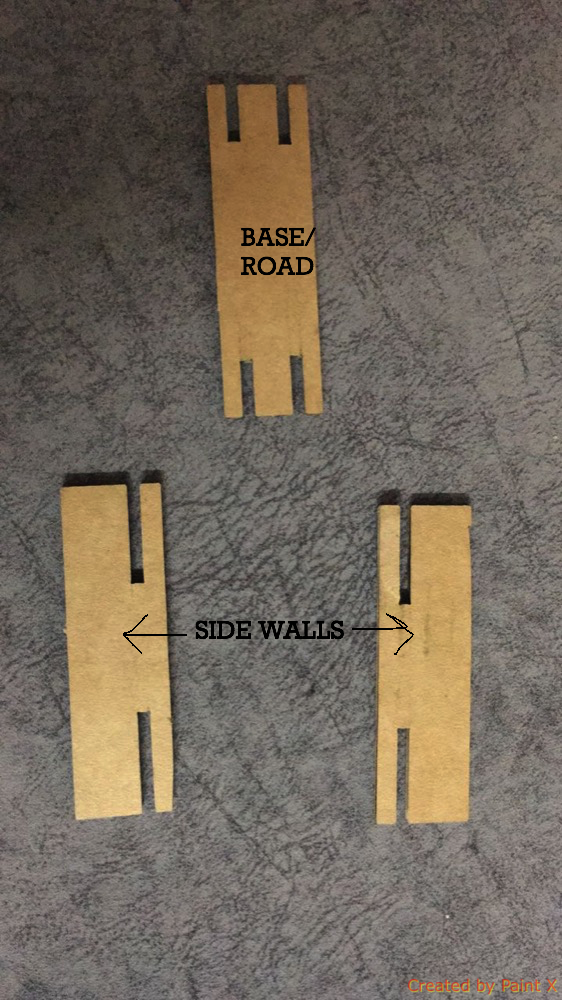
MATE -
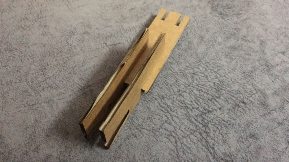
The joints are pretty strong :
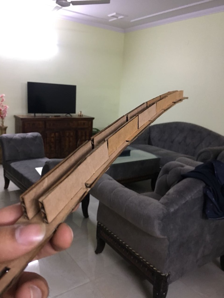
FILE Name in the source folder :side_walls.SLDPRT
Car
- I designed a simple car on solidworks, to be press
- Cardboard :
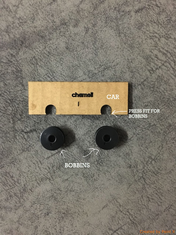
- With bobbin :
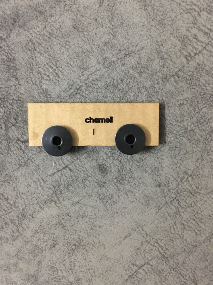
FILE Name in the source folder :car.SLDPRT
- Video of car:
Video :
- Working video of the track and car :