Week 21
Final Project Documentation
Workflow
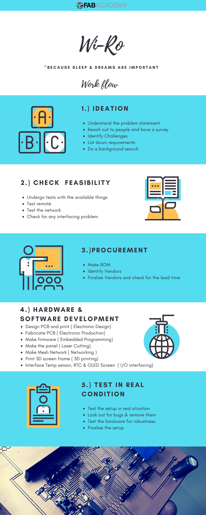
Ideation Stage
You may read about my Final Project Wi-Ro, From this LINK
Checking Feasability
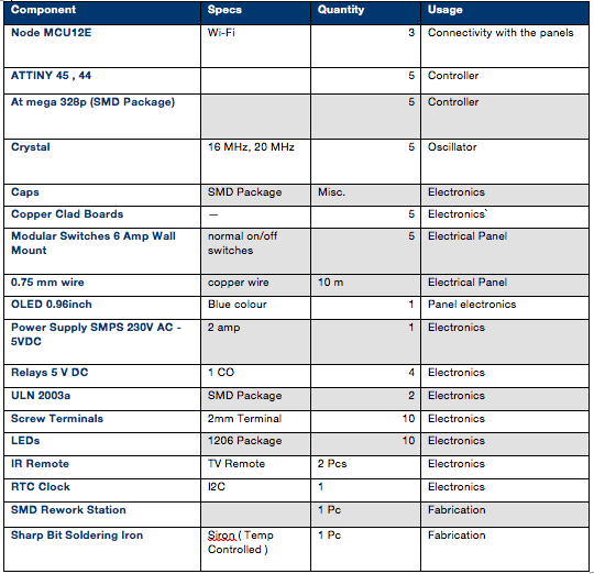
Procurement
Hardware and Software development
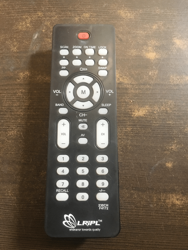
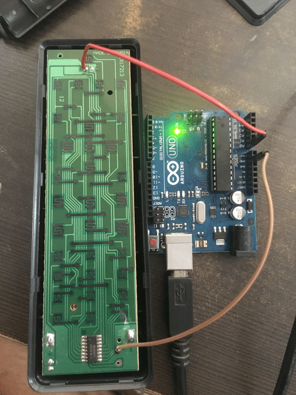
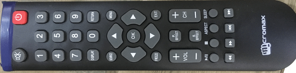
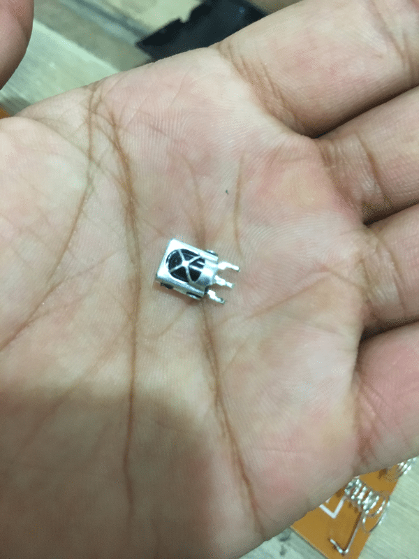
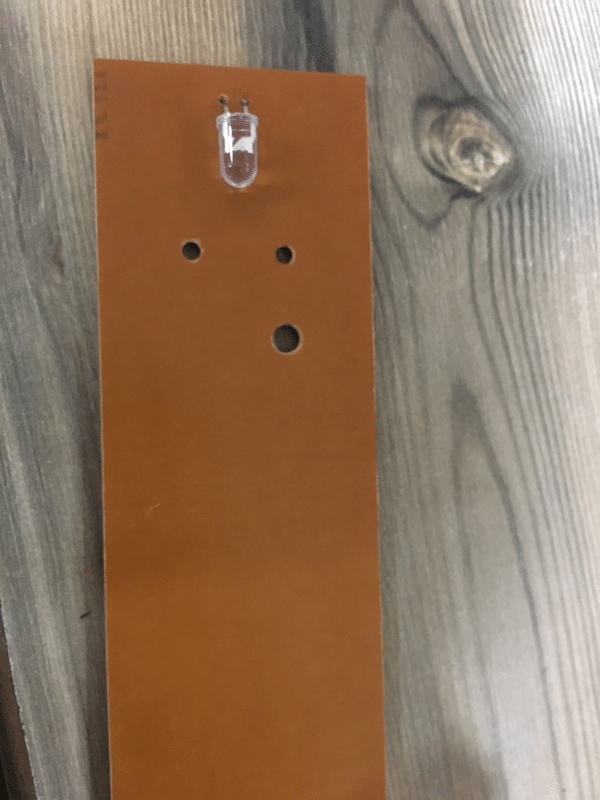
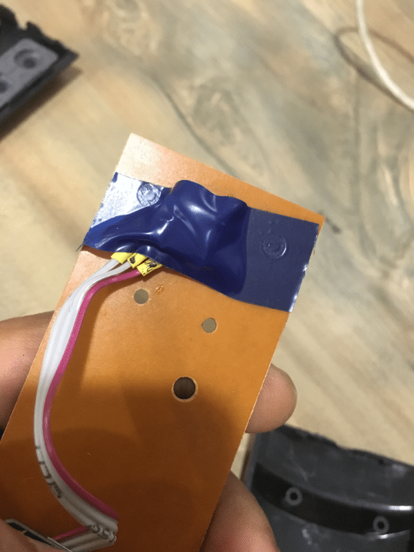
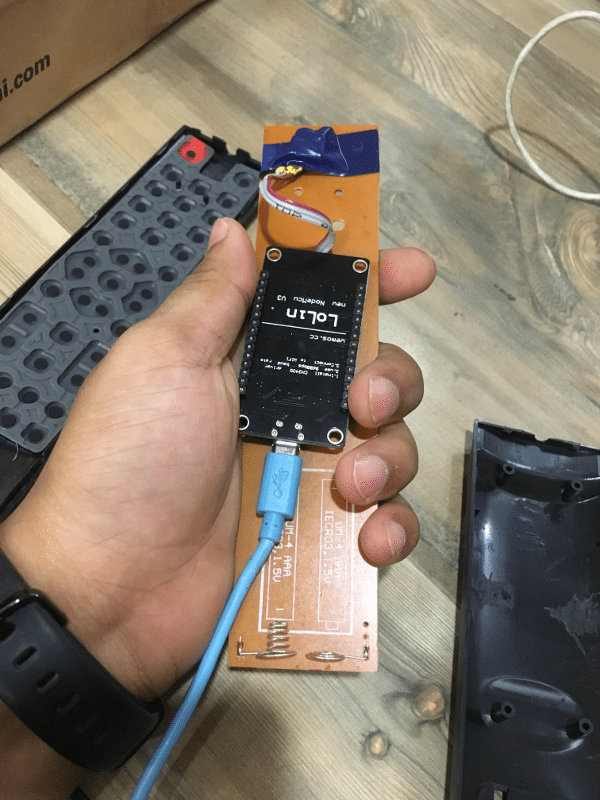
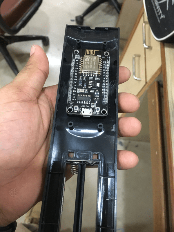
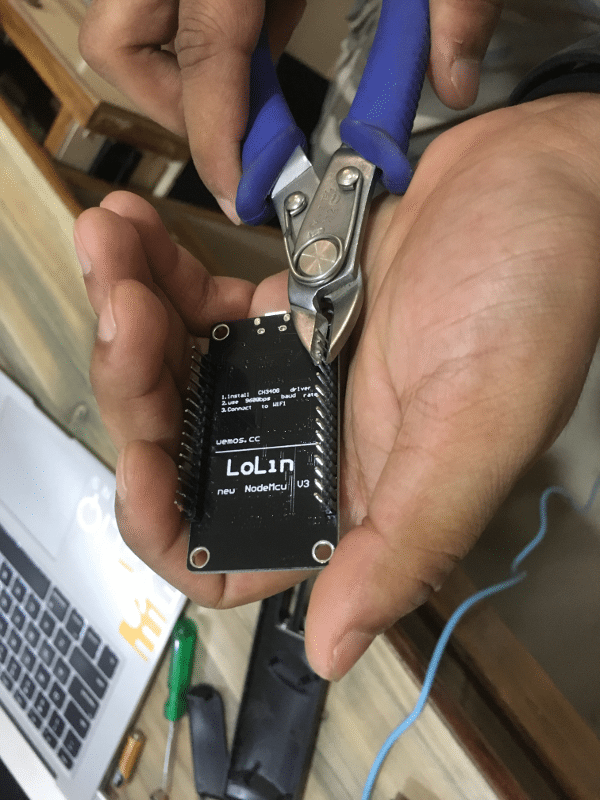
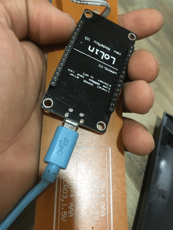
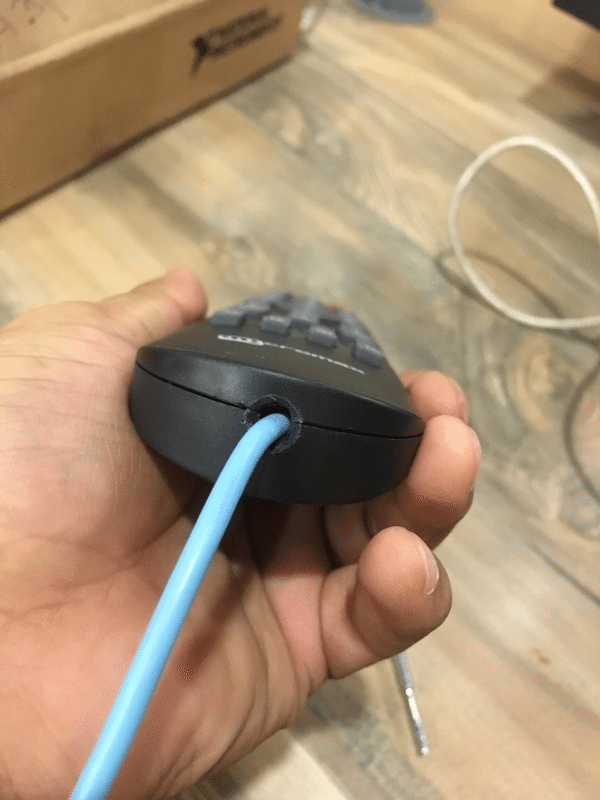
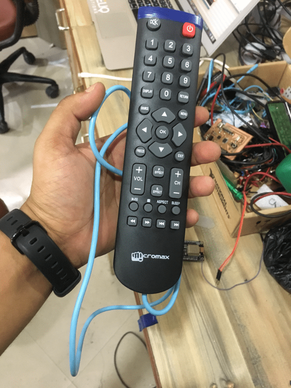
Hacking into IR Remote
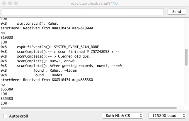
Testing the network
#include "painlessMesh.h" #define LED 2 // GPIO #define BLINK_PERIOD 3000 #define BLINK_DURATION 100 #define MESH_SSID "Rahul" #define MESH_PASSWORD "heyo1234" #define MESH_PORT 5555 painlessMesh mesh; bool calc_delay = false; SimpleListnodes; long int rahul; void sendMessage() ; // Prototype Task taskSendMessage( TASK_SECOND * 1, TASK_FOREVER, &sendMessage ); // start with a one second interval // Task to blink the number of nodes Task blinkNoNodes; bool onFlag = false; void setup() { Serial.begin(115200); pinMode(LED, OUTPUT); pinMode(D2, INPUT); pinMode(D1, INPUT); //mesh.setDebugMsgTypes( ERROR | MESH_STATUS | CONNECTION | SYNC | COMMUNICATION | GENERAL | MSG_TYPES | REMOTE ); // all types on //mesh.setDebugMsgTypes(ERROR | DEBUG | CONNECTION | COMMUNICATION); // set before init() so that you can see startup messages mesh.setDebugMsgTypes(ERROR | DEBUG | CONNECTION); // set before init() so that you can see startup messages mesh.init(MESH_SSID, MESH_PASSWORD, MESH_PORT); mesh.onReceive(&receivedCallback); mesh.onNewConnection(&newConnectionCallback); mesh.onChangedConnections(&changedConnectionCallback); mesh.onNodeTimeAdjusted(&nodeTimeAdjustedCallback); mesh.onNodeDelayReceived(&delayReceivedCallback); mesh.scheduler.addTask( taskSendMessage ); taskSendMessage.enable() ; blinkNoNodes.set(BLINK_PERIOD, (mesh.getNodeList().size() + 1) * 2, []() { // If on, switch off, else switch on if (onFlag) onFlag = false; else onFlag = true; blinkNoNodes.delay(BLINK_DURATION); if (blinkNoNodes.isLastIteration()) { blinkNoNodes.setIterations((mesh.getNodeList().size() + 1) * 2); blinkNoNodes.enableDelayed(BLINK_PERIOD - (mesh.getNodeTime() % (BLINK_PERIOD*1000))/1000); } }); mesh.scheduler.addTask(blinkNoNodes); blinkNoNodes.enable(); randomSeed(analogRead(A0)); } void loop() { mesh.update(); digitalWrite(LED, !onFlag); } void sendMessage() { String msg = "Hello from node "; msg += mesh.getNodeId(); msg += " myFreeMemory: " + String(ESP.getFreeHeap()); msg += " noTasks: " + String(mesh.scheduler.size()); bool error = mesh.sendBroadcast(msg); if (calc_delay) { SimpleList ::iterator node = nodes.begin(); while (node != nodes.end()) { mesh.startDelayMeas(*node); node++; } calc_delay = false; } Serial.printf("Sending message: %s\n", msg.c_str()); taskSendMessage.setInterval( random(TASK_SECOND * 1, TASK_SECOND * 5)); // between 1 and 5 seconds } void receivedCallback(uint32_t from, String & msg) { Serial.printf("startHere: Received from %u msg=%s\n", from, msg.c_str()); String str = msg.c_str(); // Serial.println(str[2]); if(str[2]=='l') { Serial.println("yes"); digitalWrite(D1, HIGH); } else { Serial.println("no"); digitalWrite(D1, LOW); } } void newConnectionCallback(uint32_t nodeId) { onFlag = false; blinkNoNodes.setIterations((mesh.getNodeList().size() + 1) * 2); blinkNoNodes.enableDelayed(BLINK_PERIOD - (mesh.getNodeTime() % (BLINK_PERIOD*1000))/1000); Serial.printf("--> startHere: New Connection, nodeId = %u\n", nodeId); } void changedConnectionCallback() { Serial.printf("Changed connections %s\n", mesh.subConnectionJson().c_str()); onFlag = false; blinkNoNodes.setIterations((mesh.getNodeList().size() + 1) * 2); blinkNoNodes.enableDelayed(BLINK_PERIOD - (mesh.getNodeTime() % (BLINK_PERIOD*1000))/1000); nodes = mesh.getNodeList(); Serial.printf("Num nodes: %d\n", nodes.size()); Serial.printf("Connection list:"); SimpleList ::iterator node = nodes.begin(); while (node != nodes.end()) { Serial.printf(" %u", *node); node++; } Serial.println(); calc_delay = true; } void nodeTimeAdjustedCallback(int32_t offset) { Serial.printf("Adjusted time %u. Offset = %d\n", mesh.getNodeTime(), offset); } void delayReceivedCallback(uint32_t from, int32_t delay) { Serial.printf("Delay to node %u is %d us\n", from, delay); }
 Download Test Codes/Library for Mesh Network
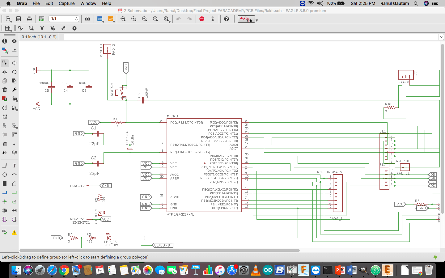
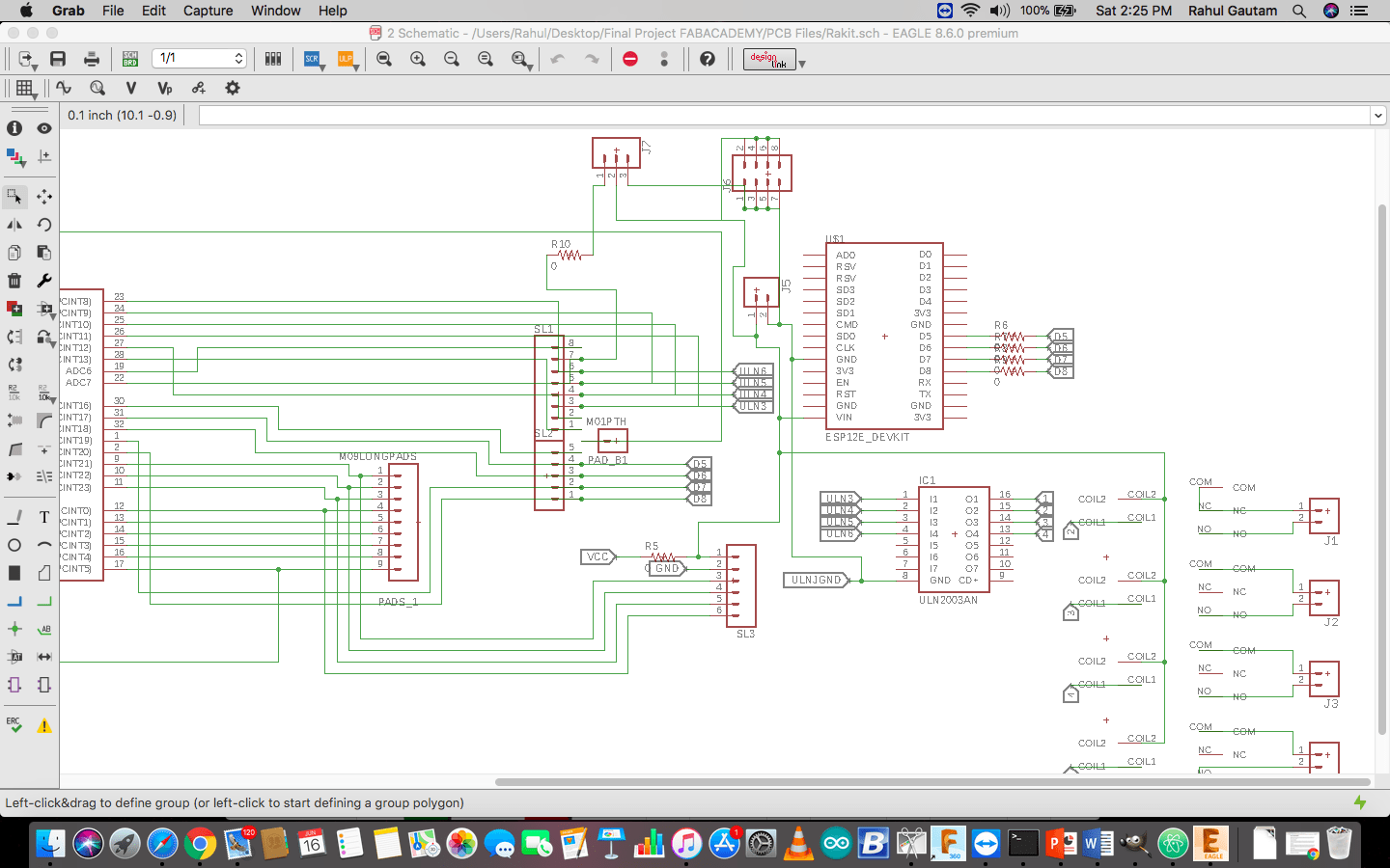
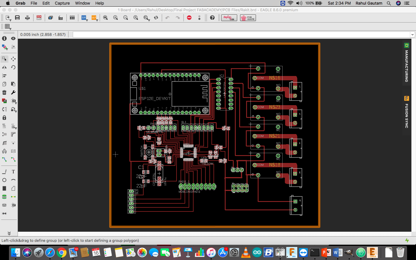
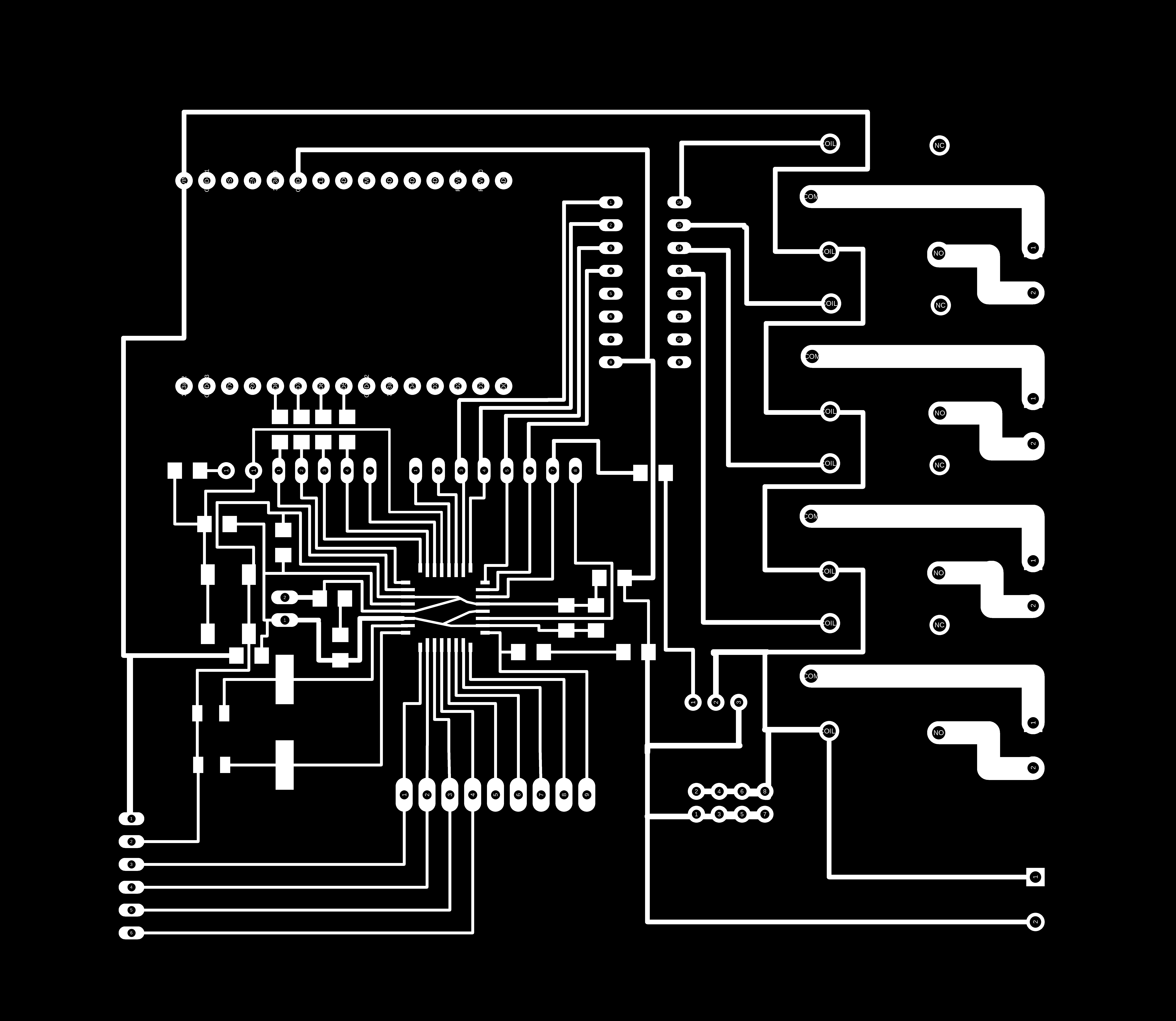
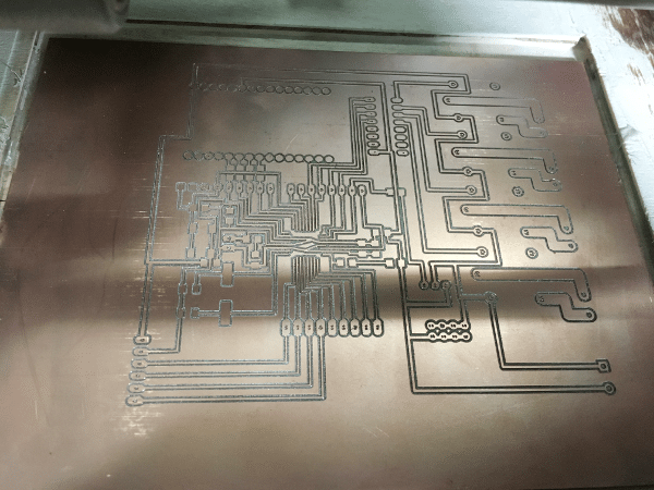
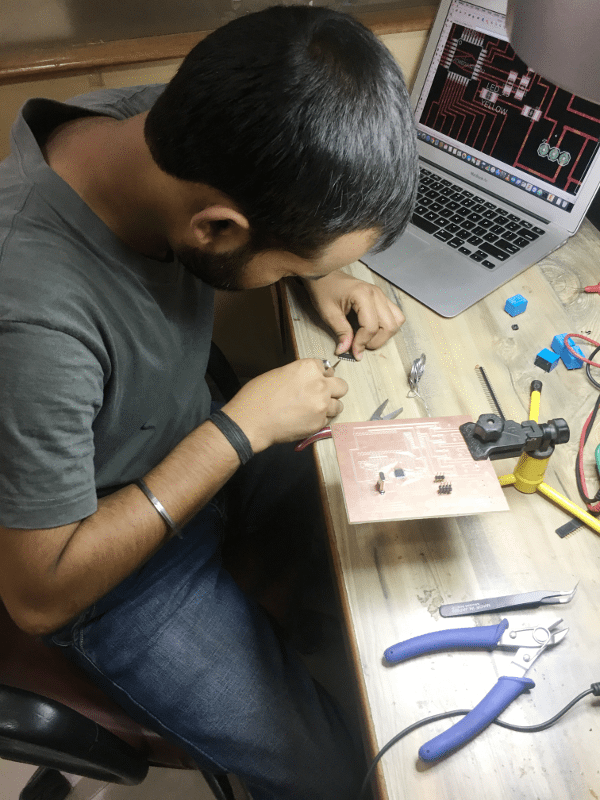
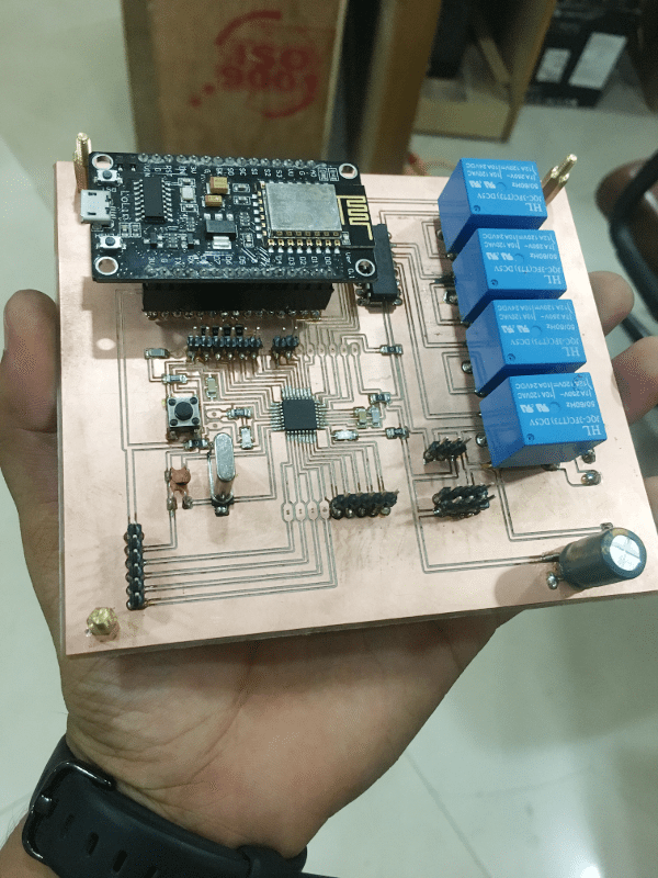
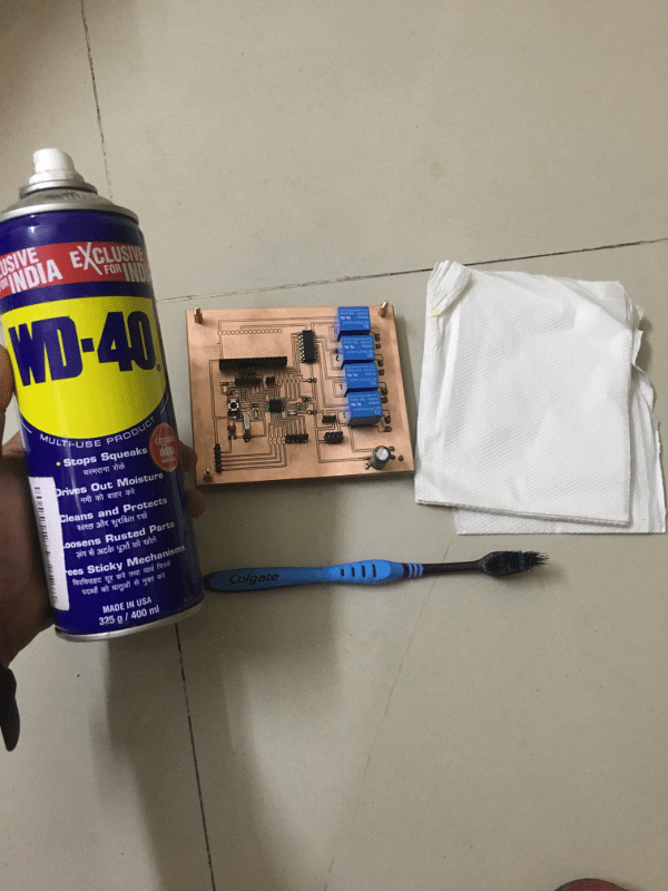
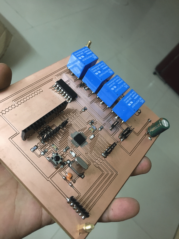
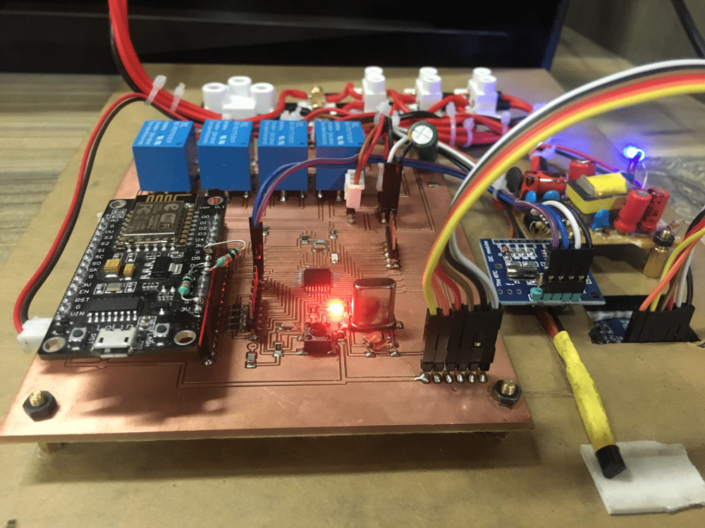
Making PCB
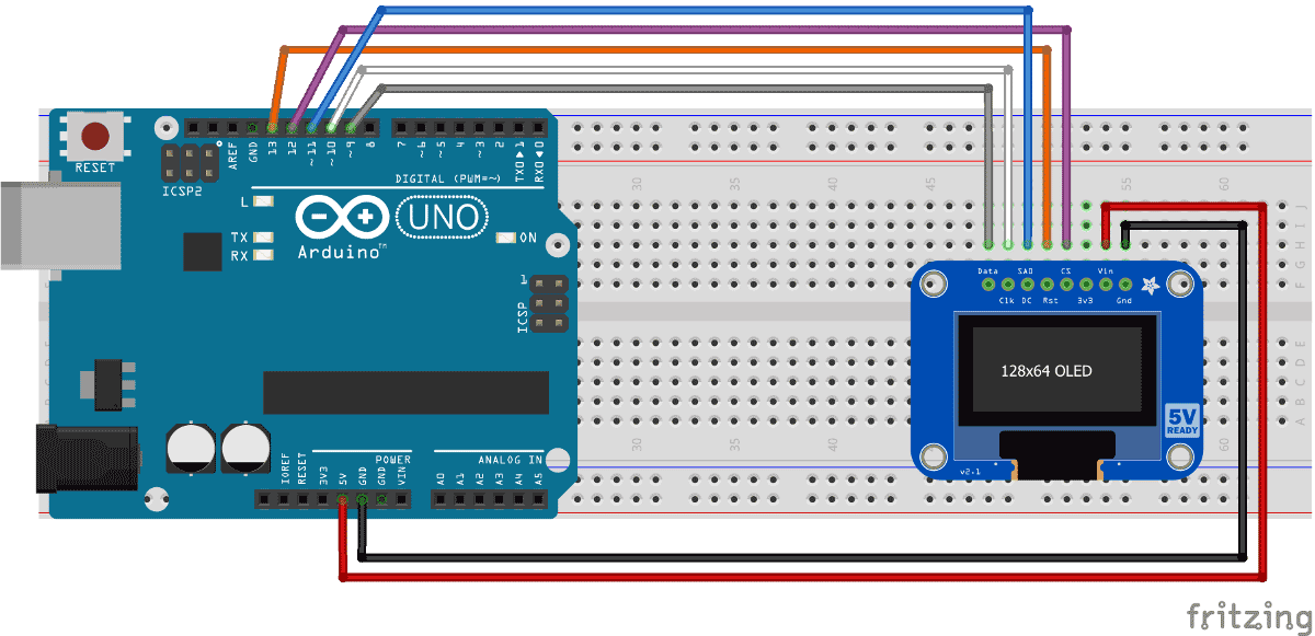
Testing OLED with the Board
          #include "SPI.h"
          #include "Wire.h"
          #include "Adafruit_GFX.h"
          #include "Adafruit_SSD1306.h"

          // If using software SPI (the default case):
          #define OLED_MOSI   5
          #define OLED_CLK   6
          #define OLED_DC    7
          #define OLED_CS    9
          #define OLED_RESET 8
          Adafruit_SSD1306 display(OLED_MOSI, OLED_CLK, OLED_DC, OLED_RESET, OLED_CS);

          /* Uncomment this block to use hardware SPI
          #define OLED_DC     6
          #define OLED_CS     7
          #define OLED_RESET  8
          Adafruit_SSD1306 display(OLED_DC, OLED_RESET, OLED_CS);
          */

          #define NUMFLAKES 10
          #define XPOS 0
          #define YPOS 1
          #define DELTAY 2

          #define LOGO16_GLCD_HEIGHT 16
          #define LOGO16_GLCD_WIDTH  16
          static const unsigned char PROGMEM logo16_glcd_bmp[] =
          { B00000000, B11000000,
            B00000001, B11000000,
            B00000001, B11000000,
            B00000011, B11100000,
            B11110011, B11100000,
            B11111110, B11111000,
            B01111110, B11111111,
            B00110011, B10011111,
            B00011111, B11111100,
            B00001101, B01110000,
            B00011011, B10100000,
            B00111111, B11100000,
            B00111111, B11110000,
            B01111100, B11110000,
            B01110000, B01110000,
            B00000000, B00110000 };

          #if (SSD1306_LCDHEIGHT != 32)
          #error("Height incorrect, please fix Adafruit_SSD1306.h!");
          #endif

          void setup()   {
            Serial.begin(9600);

            // by default, we'll generate the high voltage from the 3.3v line internally! (neat!)
            display.begin(SSD1306_SWITCHCAPVCC);
            // init done

            // Show image buffer on the display hardware.
            // Since the buffer is intialized with an Adafruit splashscreen
            // internally, this will display the splashscreen.
            display.display();
            delay(2000);

            // Clear the buffer.
            display.clearDisplay();

            // draw a single pixel
            display.drawPixel(10, 10, WHITE);
            // Show the display buffer on the hardware.
            // NOTE: You _must_ call display after making any drawing commands
            // to make them visible on the display hardware!
            display.display();
            delay(2000);
            display.clearDisplay();

            // draw many lines
            testdrawline();
            display.display();
            delay(2000);
            display.clearDisplay();

            // draw rectangles
            testdrawrect();
            display.display();
            delay(2000);
            display.clearDisplay();

            // draw multiple rectangles
            testfillrect();
            display.display();
            delay(2000);
            display.clearDisplay();

            // draw mulitple circles
            testdrawcircle();
            display.display();
            delay(2000);
            display.clearDisplay();

            // draw a white circle, 10 pixel radius
            display.fillCircle(display.width()/2, display.height()/2, 10, WHITE);
            display.display();
            delay(2000);
            display.clearDisplay();

            testdrawroundrect();
            delay(2000);
            display.clearDisplay();

            testfillroundrect();
            delay(2000);
            display.clearDisplay();

            testdrawtriangle();
            delay(2000);
            display.clearDisplay();

            testfilltriangle();
            delay(2000);
            display.clearDisplay();

            // draw the first ~12 characters in the font
            testdrawchar();
            display.display();
            delay(2000);
            display.clearDisplay();

            // draw scrolling text
            testscrolltext();
            delay(2000);
            display.clearDisplay();

            // text display tests
            display.setTextSize(1);
            display.setTextColor(WHITE);
            display.setCursor(0,0);
            display.println("Hello, world!");
            display.setTextColor(BLACK, WHITE); // 'inverted' text
            display.println(3.141592);
            display.setTextSize(2);
            display.setTextColor(WHITE);
            display.print("0x"); display.println(0xDEADBEEF, HEX);
            display.display();
            delay(2000);
            display.clearDisplay();

            // miniature bitmap display
            display.drawBitmap(30, 16,  logo16_glcd_bmp, 16, 16, 1);
            display.display();

            // invert the display
            display.invertDisplay(true);
            delay(1000);
            display.invertDisplay(false);
            delay(1000);
            display.clearDisplay();

            // draw a bitmap icon and 'animate' movement
            testdrawbitmap(logo16_glcd_bmp, LOGO16_GLCD_HEIGHT, LOGO16_GLCD_WIDTH);
          }


          void loop() {

          }


          void testdrawbitmap(const uint8_t *bitmap, uint8_t w, uint8_t h) {
            uint8_t icons[NUMFLAKES][3];

            // initialize
            for (uint8_t f=0; f< NUMFLAKES; f++) {
              icons[f][XPOS] = random(display.width());
              icons[f][YPOS] = 0;
              icons[f][DELTAY] = random(5) + 1;

              Serial.print("x: ");
              Serial.print(icons[f][XPOS], DEC);
              Serial.print(" y: ");
              Serial.print(icons[f][YPOS], DEC);
              Serial.print(" dy: ");
              Serial.println(icons[f][DELTAY], DEC);
            }

            while (1) {
              // draw each icon
              for (uint8_t f=0; f< NUMFLAKES; f++) {
                display.drawBitmap(icons[f][XPOS], icons[f][YPOS], bitmap, w, h, WHITE);
              }
              display.display();
              delay(200);

              // then erase it + move it
              for (uint8_t f=0; f< NUMFLAKES; f++) {
                display.drawBitmap(icons[f][XPOS], icons[f][YPOS], bitmap, w, h, BLACK);
                // move it
                icons[f][YPOS] += icons[f][DELTAY];
                // if its gone, reinit
                if (icons[f][YPOS] > display.height()) {
                  icons[f][XPOS] = random(display.width());
                  icons[f][YPOS] = 0;
                  icons[f][DELTAY] = random(5) + 1;
                }
              }
             }
          }


          void testdrawchar(void) {
            display.setTextSize(1);
            display.setTextColor(WHITE);
            display.setCursor(0,0);

            for (uint8_t i=0; i < 168; i++) {
              if (i == '\n') continue;
              display.write(i);
              if ((i > 0) && (i % 21 == 0))
                display.println();
            }
            display.display();
          }

          void testdrawcircle(void) {
            for (int16_t i=0; i0; i-=5) {
              display.fillTriangle(display.width()/2, display.height()/2-i,
                               display.width()/2-i, display.height()/2+i,
                               display.width()/2+i, display.height()/2+i, WHITE);
              if (color == WHITE) color = BLACK;
              else color = WHITE;
              display.display();
            }
          }

          void testdrawroundrect(void) {
            for (int16_t i=0; i=0; i-=4) {
              display.drawLine(0, display.height()-1, display.width()-1, i, WHITE);
              display.display();
            }
            delay(250);

            display.clearDisplay();
            for (int16_t i=display.width()-1; i>=0; i-=4) {
              display.drawLine(display.width()-1, display.height()-1, i, 0, WHITE);
              display.display();
            }
            for (int16_t i=display.height()-1; i>=0; i-=4) {
              display.drawLine(display.width()-1, display.height()-1, 0, i, WHITE);
              display.display();
            }
            delay(250);

            display.clearDisplay();
            for (int16_t i=0; i<=display.height(); i+=4) {
              display.drawLine(display.width()-1, 0, 0, i, WHITE);
              display.display();
            }
            for (int16_t i=0; i<=display.width(); i+=4) {
              display.drawLine(display.width()-1, 0, i, display.height()-1, WHITE);
              display.display();
            }
            delay(250);
          }

          void testscrolltext(void) {
            display.setTextSize(2);
            display.setTextColor(WHITE);
            display.setCursor(10,0);
            display.clearDisplay();
            display.println("scroll");
            display.display();

            display.startscrollright(0x00, 0x0F);
            delay(2000);
            display.stopscroll();
            delay(1000);
            display.startscrollleft(0x00, 0x0F);
            delay(2000);
            display.stopscroll();
            delay(1000);
            display.startscrolldiagright(0x00, 0x07);
            delay(2000);
            display.startscrolldiagleft(0x00, 0x07);
            delay(2000);
            display.stopscroll();
          }
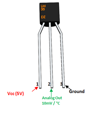
 int val;
 int tempPin = 7;

 void setup()
 {
 Serial.begin(9600);
 }
 void loop()
 {
 val = analogRead(tempPin);
 float mv = ( val/1024.0)*5000;
 float cel = mv/10;
 float farh = (cel*9)/5 + 32;

 Serial.print("TEMPRATURE = ");
 Serial.print(cel);
 Serial.print("*C");
 Serial.println();
 delay(1000);
  }
  #include "SPI.h"
  #include "Wire.h"
  #include "Adafruit_GFX.h"
  #include "Adafruit_SSD1306.h"
  #include "TimeLib.h"
  #include "DS1307RTC.h"
  //DS3231 rtc(SDA, SCL);
  #define OLED_MOSI 5
  #define OLED_CLK 6
  #define OLED_DC 7
  #define OLED_CS 9
  #define OLED_RESET 8
  Adafruit_SSD1306 display(OLED_MOSI, OLED_CLK, OLED_DC, OLED_RESET, OLED_CS);
  const int sensor_pin = A7;
  float temp;
  float output;
  float ra;
  void setup()
  {
      Serial.begin(9600);

  pinMode(sensor_pin,INPUT);
  display.begin(SSD1306_SWITCHCAPVCC);
  Serial.println("hello");
  //rtc.setDOW(WEDNESDAY);     // Set Day-of-Week to SUNDAY
  //rtc.setTime(19, 02, 0);     // Set the time to 12:00:00 (24hr format)
  //rtc.setDate(7, 12, 2017);   // Set the date to June 6th, 2017
  display.clearDisplay();
  display.setTextColor(WHITE);
  display.setTextSize(2);
  display.setCursor(0,0);
  display.print("   Wi-Ro ");
  display.setCursor(0,17);
  display.print("  by Rahul");
  display.display();
  delay(5000);
  }

  void loop()
  {
      tmElements_t tm;

  output = analogRead(sensor_pin);
  ra = ( output/1024.0)*5000;
  temp = ra/10;
    if (RTC.read(tm)) {

  display.clearDisplay();
  display.setTextSize(2);
  display.setCursor(20,0);
  display.print(tm.Hour);
      display.print(':');
     display.print(tm.Minute);
      display.print(':');
     display.print(tm.Second);
  display.setTextSize(1);
  display.setCursor(0,15);
  display.print(tm.Day);
      display.print('/');
      display.print(tm.Month);
      display.print('/');
      display.print(tmYearToCalendar(tm.Year));
      display.setTextSize(1);
  display.setCursor(70,15);
    int r = dow(tmYearToCalendar(tm.Year),tm.Month,tm.Day);
   switch(r)
    {
      case 1 :
      display.print("Tuesday");
      break;
      case 2 :
      display.print("Wednesday");
      break;
      case 3:
      display.print("Thursday");
      break;
      case 4:
      display.print("Friday");
      break;
      case 5:
      display.println("Saturday");
      break;
      case 6:
      display.print("Sunday");
      break;
      case 7:
      display.print("Monday");
      break;

      default:
      display.print("hello");
      }
  //display.print("Wednesday");
  display.setTextSize(1);
  display.setCursor(20,25);
  display.print("Temp: ");
  display.print(temp);
  display.print("C");
  display.display();
    }
  delay(1000);
  }


  int leap (int year)
  {
    return year*365 + (year/4) - (year/100) + (year/400);
  }


  int zeller (int year, int month, int day)
  {
    year += ((month+9)/12) - 1;
    month = (month+9) % 12;
    return leap (year) + month*30 + ((6*month+5)/10) + day + 1;
  }

  int dow (int year, int month, int day)
  {
    return (zeller (year, month, day) % 7) + 1;
  }
Download Code/Arduino Library
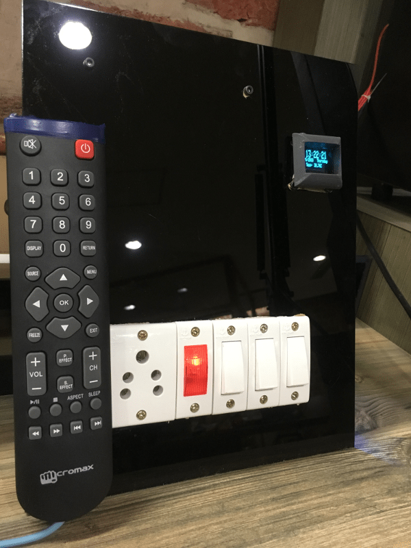
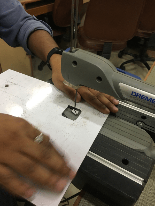
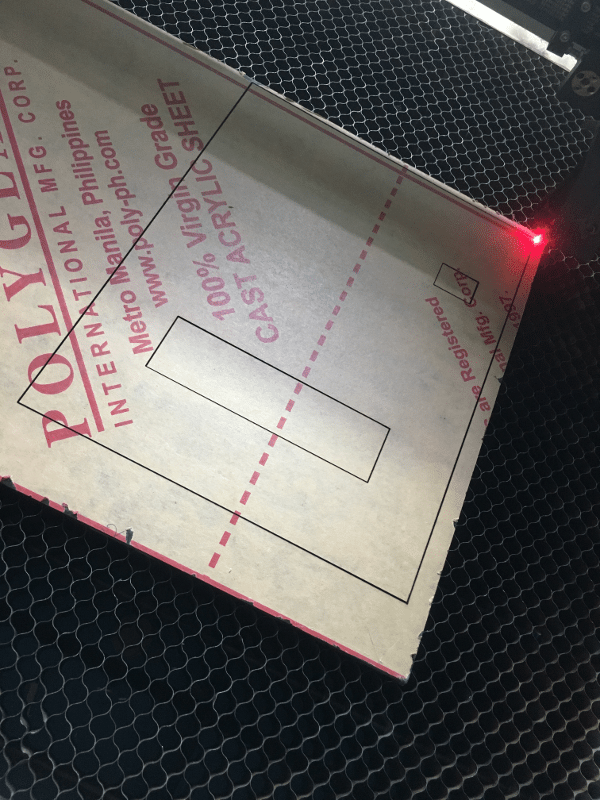
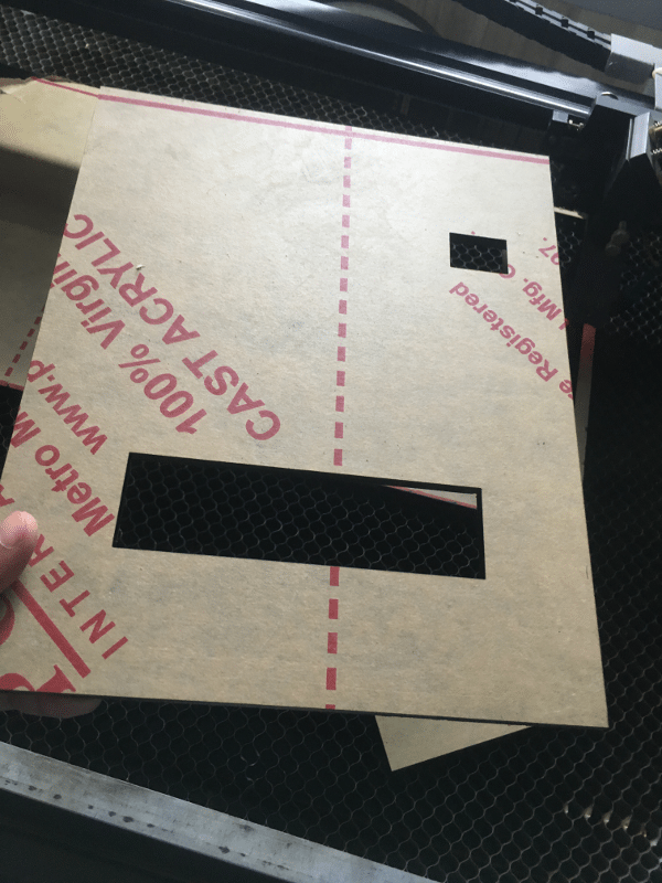
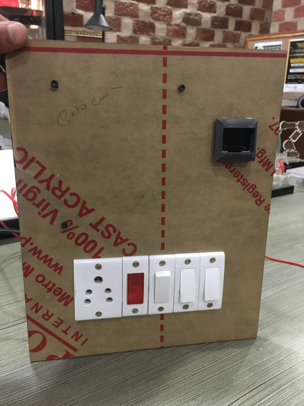
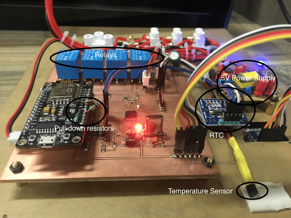
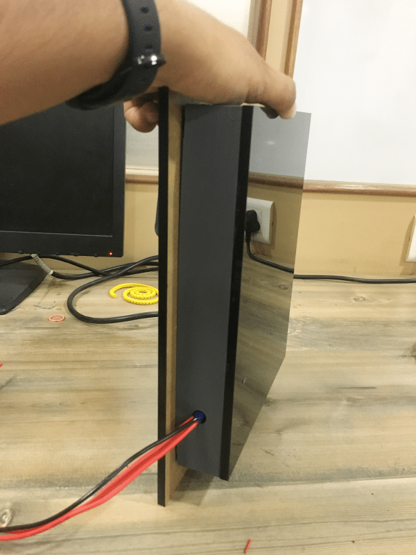
Electrical Panel
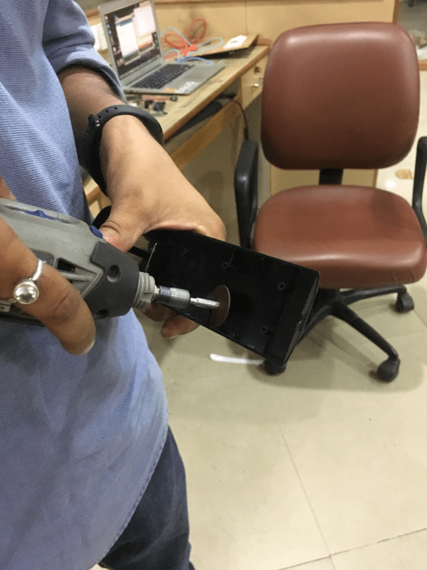
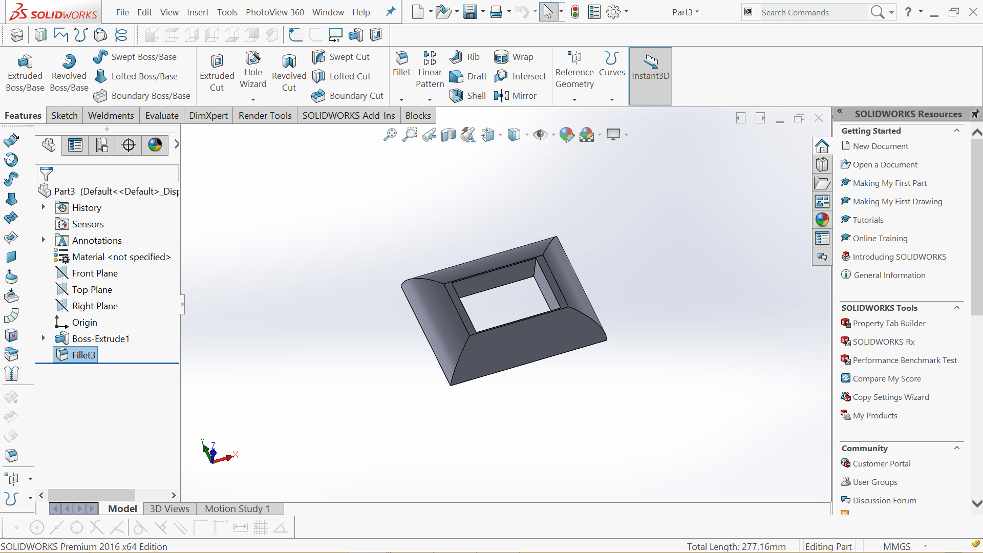
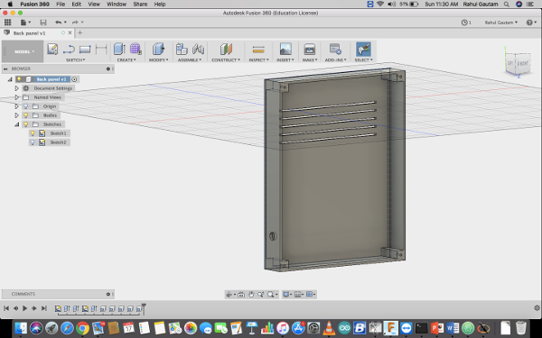
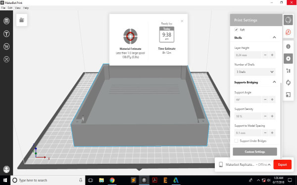
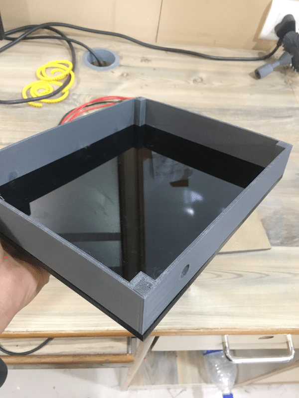
3D Frame for OLED Screen
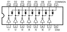
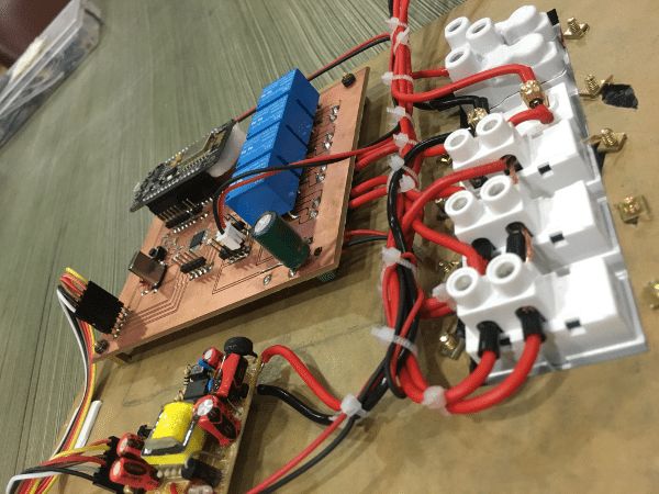
Panel Wiring
Embedded Codes
      #ifndef UNIT_TEST
      #include "Arduino.h"
      #endif
      #include "IRremoteESP8266.h"
      #include "IRrecv.h"
      #include "IRutils.h"

      #include "painlessMesh.h"
        String msg = "000000";


      #define   LED             2       // GPIO

      #define   BLINK_PERIOD    3000
      #define   BLINK_DURATION  100

      #define   MESH_SSID       "Rahul"
      #define   MESH_PASSWORD   "heyo1234"
      #define   MESH_PORT       5555

      uint16_t RECV_PIN = 14;

      IRrecv irrecv(RECV_PIN);
      int atr;
      decode_results results;

      painlessMesh  mesh;
      bool calc_delay = false;
      SimpleList nodes;
      long int rahul;
      void sendMessage() ; // Prototype
      Task taskSendMessage( TASK_SECOND * 1, TASK_FOREVER, &sendMessage ); // start with a one second interval

      // Task to blink the number of nodes
      Task blinkNoNodes;
      bool onFlag = false;

      void setup() {
        Serial.begin(115200);
        //mesh.setDebugMsgTypes( ERROR | MESH_STATUS | CONNECTION | SYNC | COMMUNICATION | GENERAL | MSG_TYPES | REMOTE ); // all types on
        //mesh.setDebugMsgTypes(ERROR | DEBUG | CONNECTION | COMMUNICATION);  // set before init() so that you can see startup messages
        mesh.setDebugMsgTypes(ERROR | DEBUG | CONNECTION);  // set before init() so that you can see startup messages

        mesh.init(MESH_SSID, MESH_PASSWORD, MESH_PORT);
        mesh.onReceive(&receivedCallback);
        mesh.onNewConnection(&newConnectionCallback);
        mesh.onChangedConnections(&changedConnectionCallback);
        mesh.onNodeTimeAdjusted(&nodeTimeAdjustedCallback);
        mesh.onNodeDelayReceived(&delayReceivedCallback);

        mesh.scheduler.addTask( taskSendMessage );
        taskSendMessage.enable() ;

        blinkNoNodes.set(BLINK_PERIOD, (mesh.getNodeList().size() + 1) * 2, []() {
            // If on, switch off, else switch on
            if (onFlag)
              onFlag = false;
            else
              onFlag = true;
            blinkNoNodes.delay(BLINK_DURATION);

            if (blinkNoNodes.isLastIteration()) {

              blinkNoNodes.setIterations((mesh.getNodeList().size() + 1) * 2);

              blinkNoNodes.enableDelayed(BLINK_PERIOD -
                  (mesh.getNodeTime() % (BLINK_PERIOD*1000))/1000);
            }
        });
        mesh.scheduler.addTask(blinkNoNodes);
        blinkNoNodes.enable();

        randomSeed(analogRead(A0));
          irrecv.enableIRIn();  // Start the receiver

      }

      void loop() {
        mesh.update();
        digitalWrite(LED, !onFlag);
        if (irrecv.decode(&results)) {
          // print() & println() can't handle printing long longs. (uint64_t)
            atr= (results.value);
            msg= String(atr);
            irrecv.resume();
            delay(10);

        }
      }

      void sendMessage() {

        bool error = mesh.sendBroadcast(msg);

        if (calc_delay) {
          SimpleList::iterator node = nodes.begin();
          while (node != nodes.end()) {
            mesh.startDelayMeas(*node);
            node++;
          }
          calc_delay = false;
        }

        Serial.printf("Sending message: %s\n", msg.c_str());

        taskSendMessage.setInterval( random(TASK_SECOND * 1, TASK_SECOND * 5));  // between 1 and 5 seconds
      }


      void receivedCallback(uint32_t from, String & msg) {
        Serial.printf("startHere: Received from %u msg=%s\n", from, msg.c_str());
        String str = msg.c_str();
       // Serial.println(str[2]);
        if(str[2]=='l')
        {
        Serial.println("yes");
       // digitalWrite(D1, HIGH);
        }
        else
        {
          Serial.println("no");
         // digitalWrite(D1, LOW);
        }

      }

      void newConnectionCallback(uint32_t nodeId) {
        onFlag = false;
        blinkNoNodes.setIterations((mesh.getNodeList().size() + 1) * 2);
        blinkNoNodes.enableDelayed(BLINK_PERIOD - (mesh.getNodeTime() % (BLINK_PERIOD*1000))/1000);

        Serial.printf("--> startHere: New Connection, nodeId = %u\n", nodeId);
      }

      void changedConnectionCallback() {
        Serial.printf("Changed connections %s\n", mesh.subConnectionJson().c_str());
        onFlag = false;
        blinkNoNodes.setIterations((mesh.getNodeList().size() + 1) * 2);
        blinkNoNodes.enableDelayed(BLINK_PERIOD - (mesh.getNodeTime() % (BLINK_PERIOD*1000))/1000);

        nodes = mesh.getNodeList();

        Serial.printf("Num nodes: %d\n", nodes.size());
        Serial.printf("Connection list:");

        SimpleList::iterator node = nodes.begin();
        while (node != nodes.end()) {
          Serial.printf(" %u", *node);
          node++;
        }
        Serial.println();
        calc_delay = true;
      }

      void nodeTimeAdjustedCallback(int32_t offset) {
        Serial.printf("Adjusted time %u. Offset = %d\n", mesh.getNodeTime(), offset);
      }

      void delayReceivedCallback(uint32_t from, int32_t delay) {
        Serial.printf("Delay to node %u is %d us\n", from, delay);
      }
        #include "painlessMesh.h"


        #define   LED             2       // GPIO

        #define   BLINK_PERIOD    3000
        #define   BLINK_DURATION  100

        #define   MESH_SSID       "Rahul"
        #define   MESH_PASSWORD   "heyo1234"
        #define   MESH_PORT       5555

        painlessMesh  mesh;
        bool calc_delay = false;
        SimpleList nodes;
        long int rahul;
        void sendMessage() ; // Prototype
        Task taskSendMessage( TASK_SECOND * 1, TASK_FOREVER, &sendMessage ); // start with a one second interval
        String hello ;
        // Task to blink the number of nodes
        Task blinkNoNodes;
        bool onFlag = false;
        //String str ="123" ;
        void setup() {
          Serial.begin(115200);

          pinMode(LED, OUTPUT);
          pinMode(D7, OUTPUT);
          pinMode(D6, OUTPUT);

          //mesh.setDebugMsgTypes( ERROR | MESH_STATUS | CONNECTION | SYNC | COMMUNICATION | GENERAL | MSG_TYPES | REMOTE ); // all types on
          //mesh.setDebugMsgTypes(ERROR | DEBUG | CONNECTION | COMMUNICATION);  // set before init() so that you can see startup messages
          mesh.setDebugMsgTypes(ERROR | DEBUG | CONNECTION);  // set before init() so that you can see startup messages

          mesh.init(MESH_SSID, MESH_PASSWORD, MESH_PORT);
          mesh.onReceive(&receivedCallback);
          mesh.onNewConnection(&newConnectionCallback);
          mesh.onChangedConnections(&changedConnectionCallback);
          mesh.onNodeTimeAdjusted(&nodeTimeAdjustedCallback);
          mesh.onNodeDelayReceived(&delayReceivedCallback);

          mesh.scheduler.addTask( taskSendMessage );
          taskSendMessage.enable() ;

          blinkNoNodes.set(BLINK_PERIOD, (mesh.getNodeList().size() + 1) * 2, []() {
              // If on, switch off, else switch on
              if (onFlag)
                onFlag = false;
              else
                onFlag = true;
              blinkNoNodes.delay(BLINK_DURATION);

              if (blinkNoNodes.isLastIteration()) {

                blinkNoNodes.setIterations((mesh.getNodeList().size() + 1) * 2);

                blinkNoNodes.enableDelayed(BLINK_PERIOD -
                    (mesh.getNodeTime() % (BLINK_PERIOD*1000))/1000);
              }
          });
          mesh.scheduler.addTask(blinkNoNodes);
          blinkNoNodes.enable();

          randomSeed(analogRead(A0));
        }

        void loop() {
          mesh.update();
          digitalWrite(LED, !onFlag);
          Serial.println(hello);
          if(hello=="876330")
          {
            digitalWrite(D6, HIGH);
            //Serial.println("d5 LOW ");
          }
          else if (hello=="847665")
          {
            digitalWrite(D6,LOW);
            //Serial.println("d5 HIGH");
          }
          else if (hello=="843570")
          {
            digitalWrite(D7,HIGH);
            //Serial.println("d6 LOW");
          }
          else if (hello=="839475")
          {
            digitalWrite(D7,LOW);
            //Serial.println("d6 HIGH");
          }
          delay(500);

          }

        void sendMessage() {


          if (calc_delay) {
            SimpleList::iterator node = nodes.begin();
            while (node != nodes.end()) {
              mesh.startDelayMeas(*node);
              node++;
            }
            calc_delay = false;
          }

          //Serial.printf("Sending message: %s\n", msg.c_str());

          taskSendMessage.setInterval( random(TASK_SECOND * 1, TASK_SECOND * 5));  // between 1 and 5 seconds
        }


        void receivedCallback(uint32_t from, String & msg) {
          Serial.printf("startHere: Received from %u msg=%s\n", from, msg.c_str());
        String  str = msg.c_str();
        hello=str;
         // Serial.println(str[2]);
          if(str=="876330")
          {
          Serial.println("yes");
          //digitalWrite(D1, HIGH);
          }
          else
          {
            Serial.println("no");
           // digitalWrite(D1, LOW);
          }

        }

        void newConnectionCallback(uint32_t nodeId) {
          onFlag = false;
          blinkNoNodes.setIterations((mesh.getNodeList().size() + 1) * 2);
          blinkNoNodes.enableDelayed(BLINK_PERIOD - (mesh.getNodeTime() % (BLINK_PERIOD*1000))/1000);

          Serial.printf("--> startHere: New Connection, nodeId = %u\n", nodeId);
        }

        void changedConnectionCallback() {
          Serial.printf("Changed connections %s\n", mesh.subConnectionJson().c_str());
          onFlag = false;
          blinkNoNodes.setIterations((mesh.getNodeList().size() + 1) * 2);
          blinkNoNodes.enableDelayed(BLINK_PERIOD - (mesh.getNodeTime() % (BLINK_PERIOD*1000))/1000);

          nodes = mesh.getNodeList();

          Serial.printf("Num nodes: %d\n", nodes.size());
          Serial.printf("Connection list:");

          SimpleList::iterator node = nodes.begin();
          while (node != nodes.end()) {
            Serial.printf(" %u", *node);
            node++;
          }
          Serial.println();
          calc_delay = true;
        }

        void nodeTimeAdjustedCallback(int32_t offset) {
          Serial.printf("Adjusted time %u. Offset = %d\n", mesh.getNodeTime(), offset);
        }

        void delayReceivedCallback(uint32_t from, int32_t delay) {
          Serial.printf("Delay to node %u is %d us\n", from, delay);
        }
    #include "SPI.h"
    #include "Wire.h"
    #include "Adafruit_GFX.h"
    #include "Adafruit_SSD1306.h"
    #include "TimeLib.h"
    #include "DS1307RTC.h"
    #define OLED_MOSI 5
    #define OLED_CLK 6
    #define OLED_DC 7
    #define OLED_CS 9
    #define OLED_RESET 8
    Adafruit_SSD1306 display(OLED_MOSI, OLED_CLK, OLED_DC, OLED_RESET, OLED_CS);
    const int sensor_pin = A7;
    float temp;
    float output;
    float ra;


    void setup()
    {
              Serial.begin(9600);
              pinMode(2,INPUT);
              pinMode(3,INPUT);
              pinMode(14,OUTPUT);
              pinMode(15,OUTPUT);
              pinMode(sensor_pin,INPUT);
              display.begin(SSD1306_SWITCHCAPVCC);
              display.clearDisplay();
              display.setTextColor(WHITE);
              display.setTextSize(2);
              display.setCursor(0,0);
              display.print("   Wi-Ro ");
              display.setCursor(0,17);
              display.print("  by Rahul");
              display.display();
              delay(5000);
    }


    void loop()
    {
        tmElements_t tm;

    output = analogRead(sensor_pin);
    ra = ( output/1024.0)*5000;
    temp = ra/10;
    if (digitalRead(3)== HIGH)
              {
                digitalWrite(14,HIGH);

              }
    if (digitalRead(3)==LOW)
              {
                digitalWrite(14,LOW);
              }
     if (digitalRead(2)==HIGH)
              {
                digitalWrite(15,HIGH);
              }
     if (digitalRead(2)==LOW)
              {
                digitalWrite(15,LOW);
              }

    if (RTC.read(tm))
      {

          display.clearDisplay();
          display.setTextSize(2);
          display.setCursor(20,0);
          display.print(tm.Hour);
          display.print(':');
          display.print(tm.Minute);
          display.print(':');
          display.print(tm.Second);
                      display.setTextSize(1);
                      display.setCursor(0,15);
                      display.print(tm.Day);
                      display.print('/');
                      display.print(tm.Month);
                      display.print('/');
                      display.print(tmYearToCalendar(tm.Year));
                                display.setTextSize(1);
                                display.setCursor(70,15);
                                  int r = dow(tmYearToCalendar(tm.Year),tm.Month,tm.Day);
                                 switch(r)
                                  {
                                    case 1 :
                                    display.print("Tuesday");
                                    break;
                                    case 2 :
                                    display.print("Wednesday");
                                    break;
                                    case 3:
                                    display.print("Thursday");
                                    break;
                                    case 4:
                                    display.print("Friday");
                                    break;
                                    case 5:
                                    display.println("Saturday");
                                    break;
                                    case 6:
                                    display.print("Sunday");
                                    break;
                                    case 7:
                                    display.print("Monday");
                                    break;

                                    default:
                                    display.print("hello");
                                    }

                                                  display.setTextSize(1);
                                                  display.setCursor(20,25);
                                                  display.print("Temp: ");
                                                  display.print(temp);
                                                  display.print("C");
                                                  display.display();
                                                    }


    delay(200);
    }


    int leap (int year)
              {
                return year*365 + (year/4) - (year/100) + (year/400);
              }


    int zeller (int year, int month, int day)
              {
                year += ((month+9)/12) - 1;
                month = (month+9) % 12;
                return leap (year) + month*30 + ((6*month+5)/10) + day + 1;
              }

    int dow (int year, int month, int day)
              {
                return (zeller (year, month, day) % 7) + 1;
              }
Download Main Codes
Test in Real Conditions