Week 17
Wild Card Week
Introduction to Composites
When Should you use Composites ?
Weight reduction
Durability and maintenance
Added functionality
Design freedom
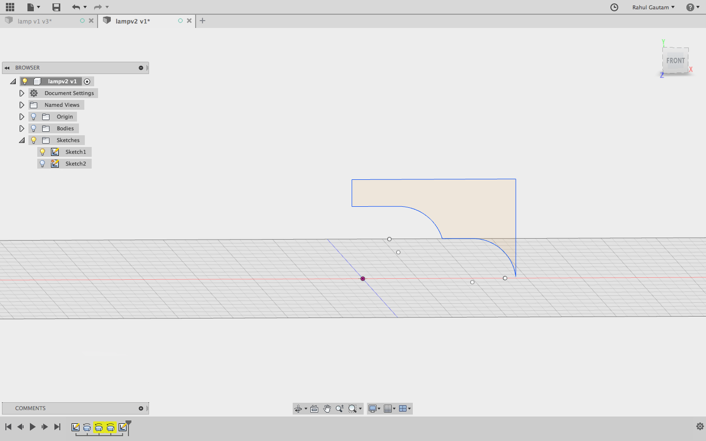
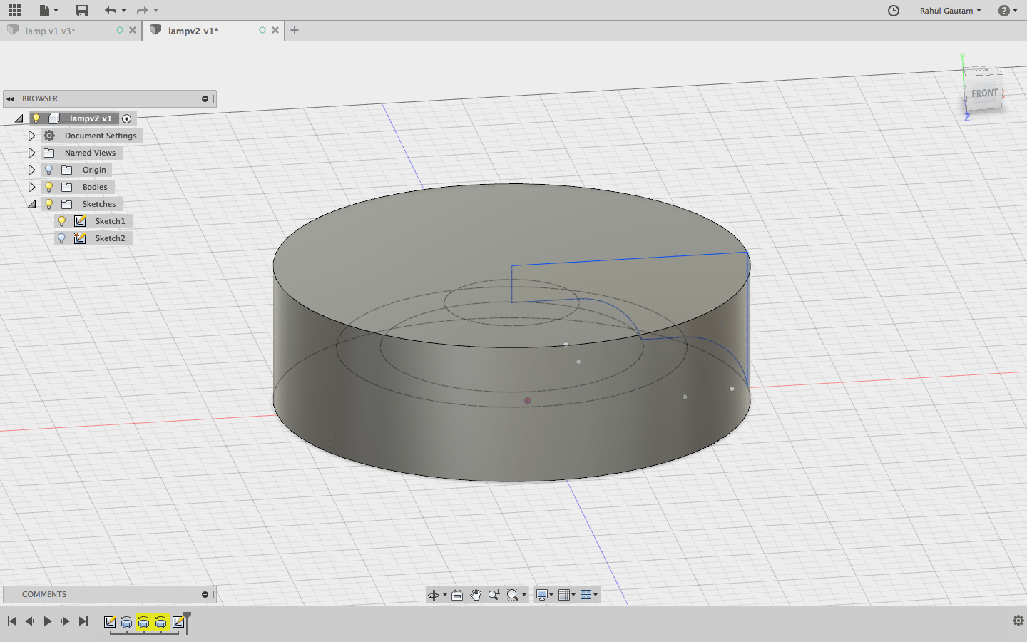
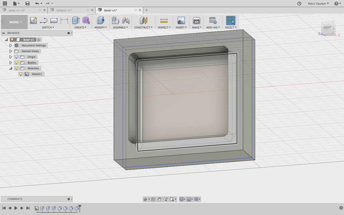
The Lamp
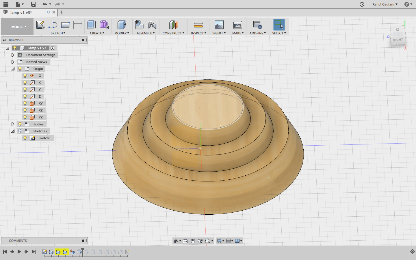
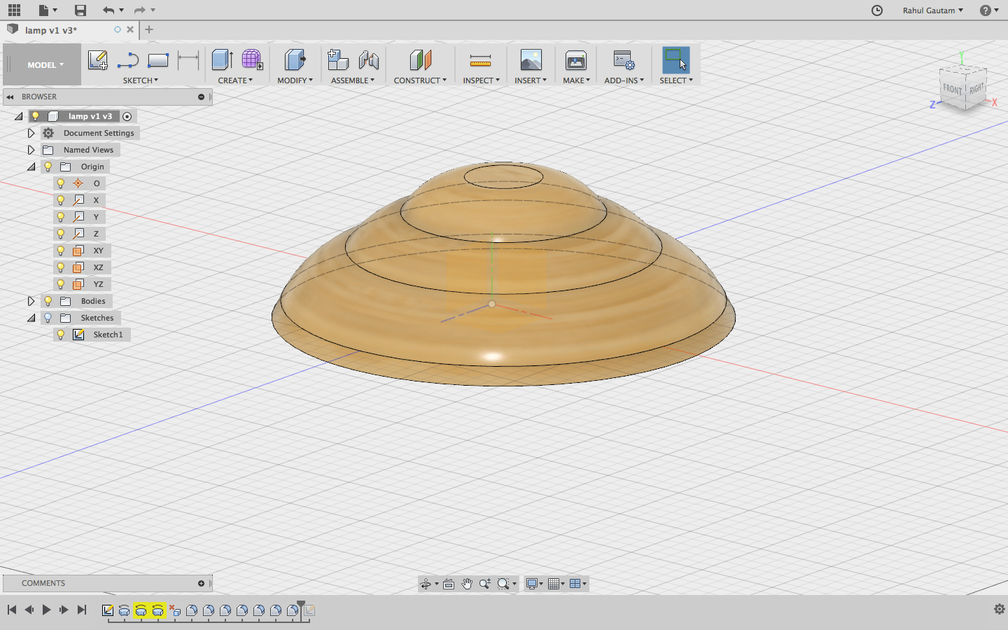
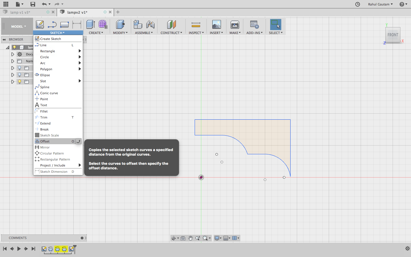
 Download Fusion Files (Lamp Shade)
Problem with this design
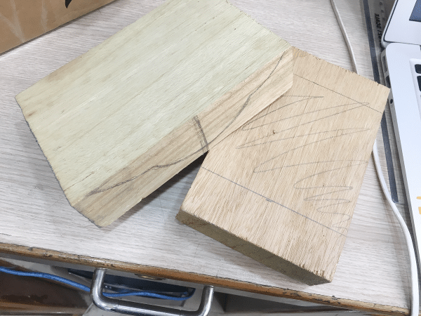
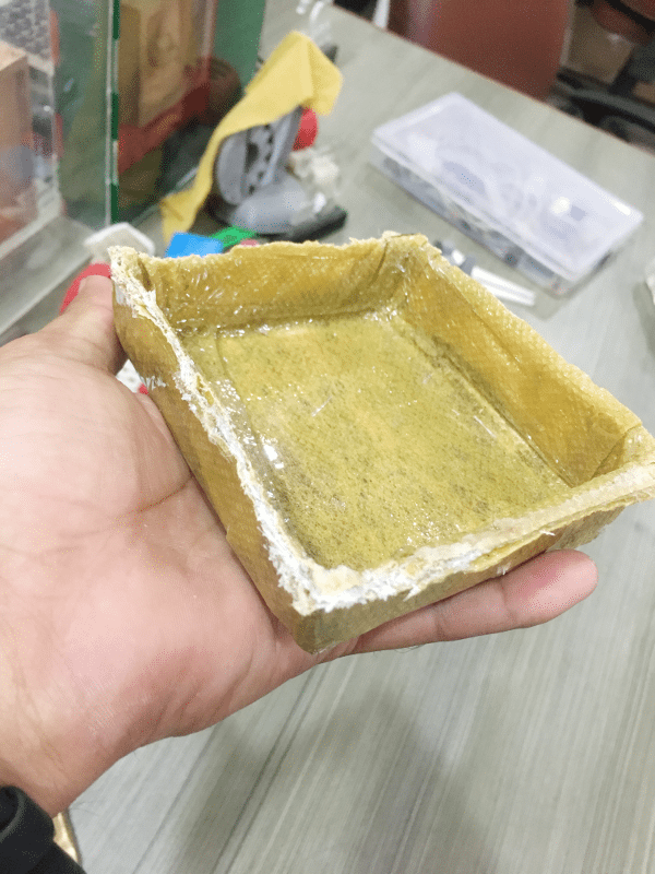
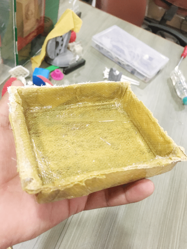
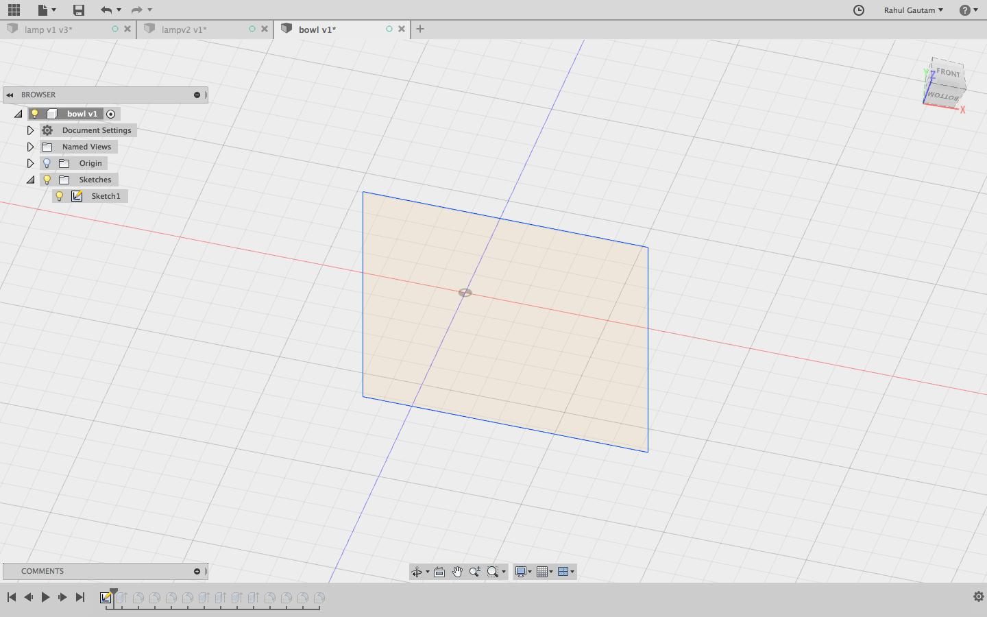
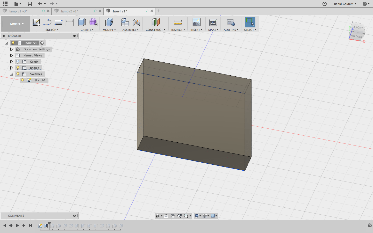
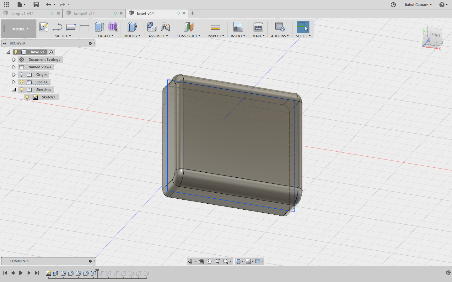
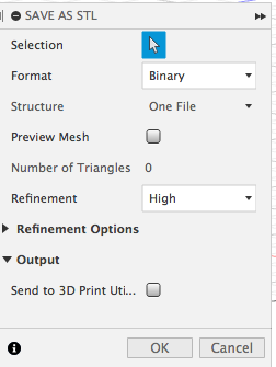
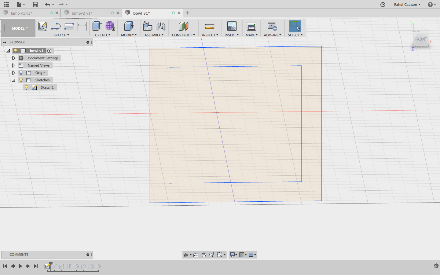
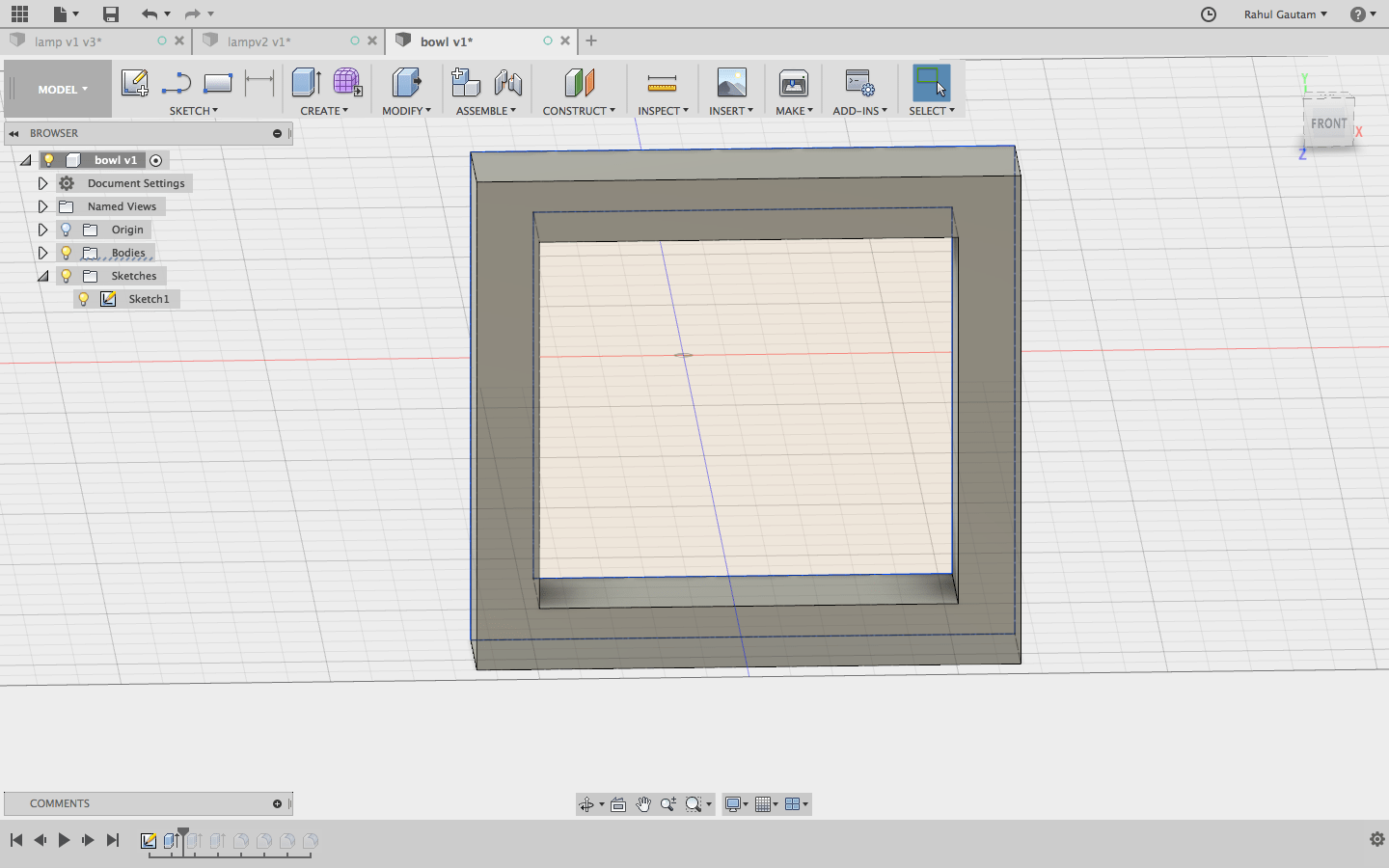
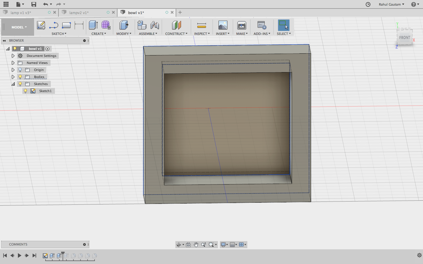
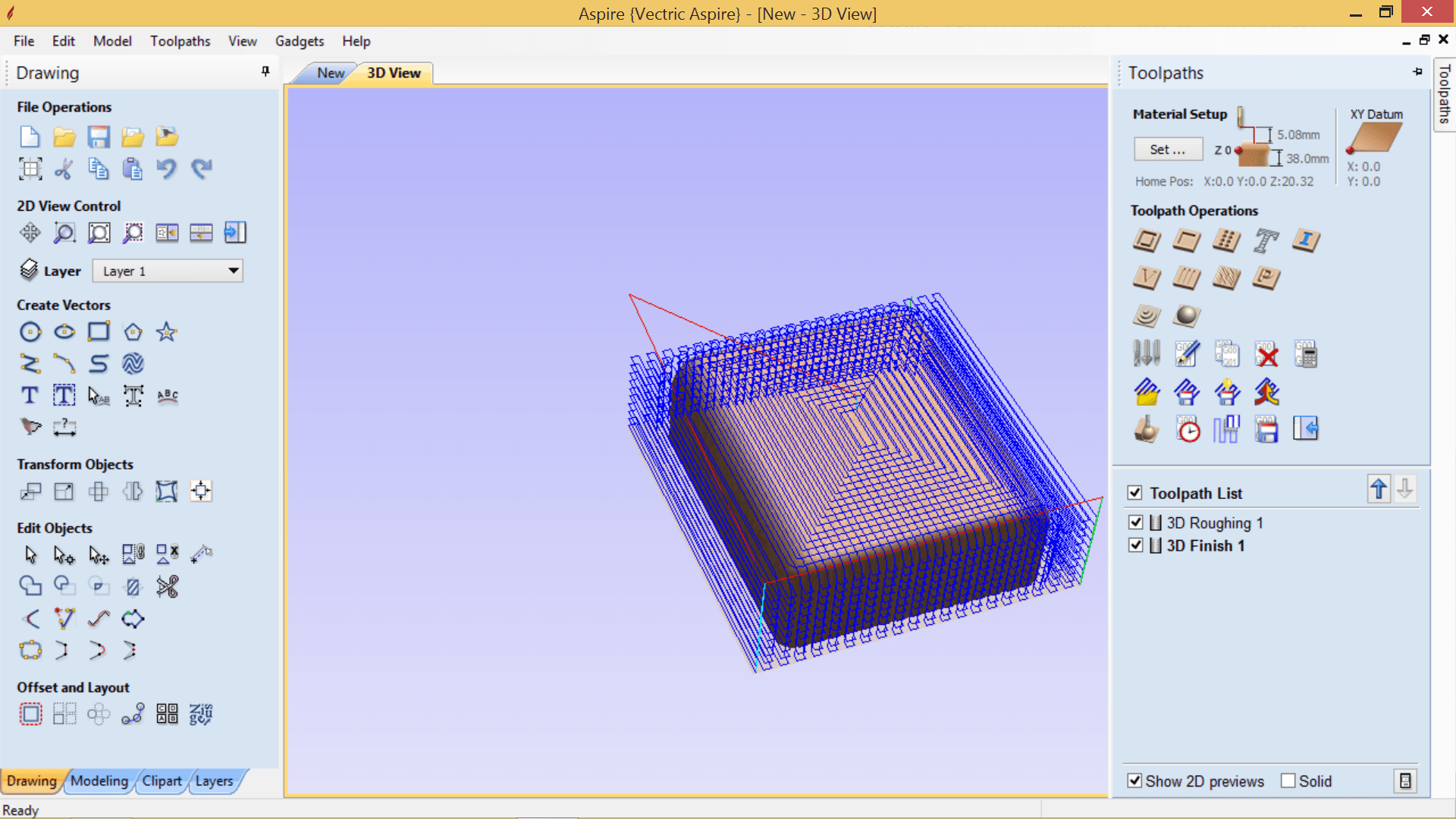
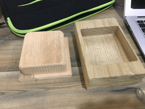
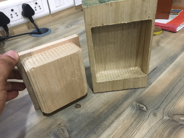
The Bowl
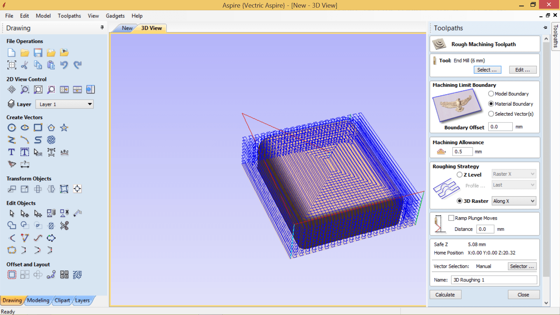
Tool Path
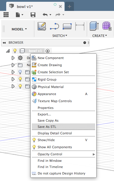
 Download CNC Files (Bowl)
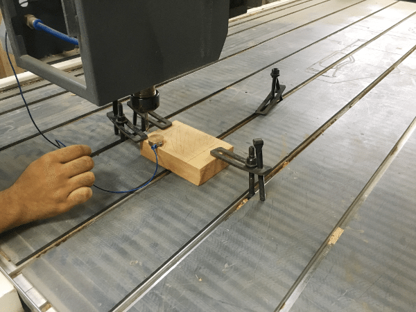
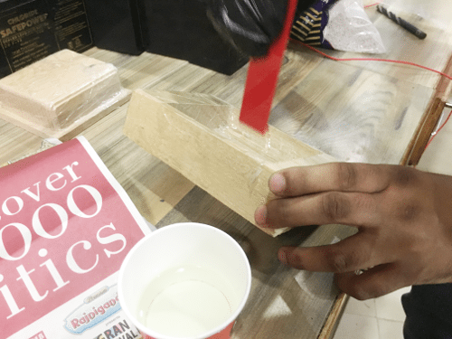
Milling
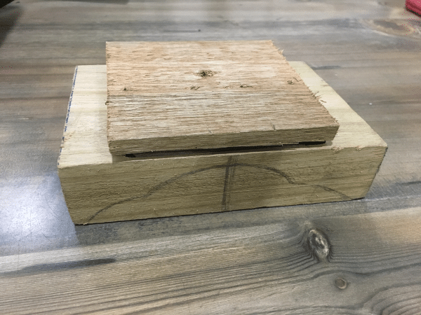
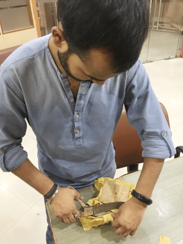
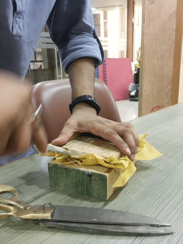
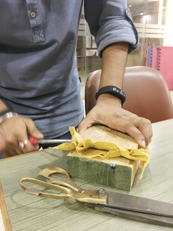
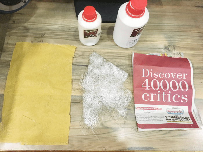
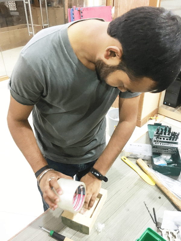
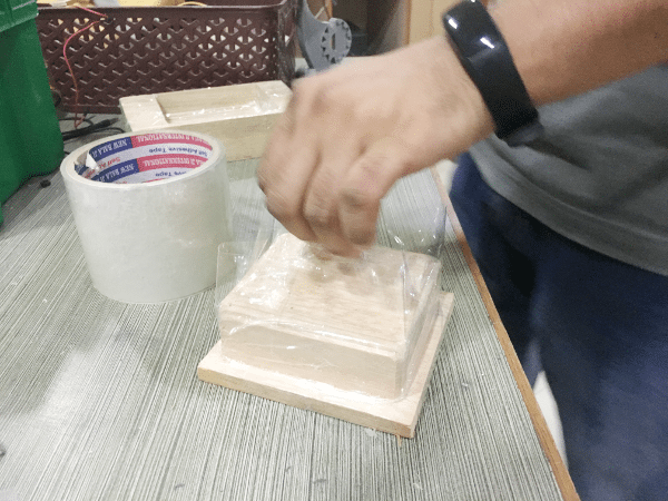
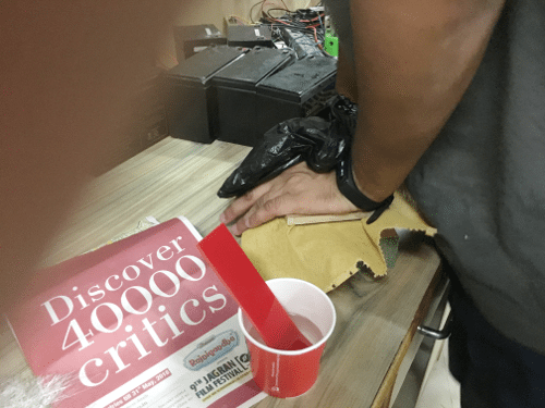
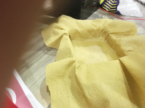
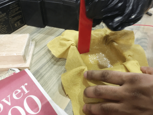
Composite
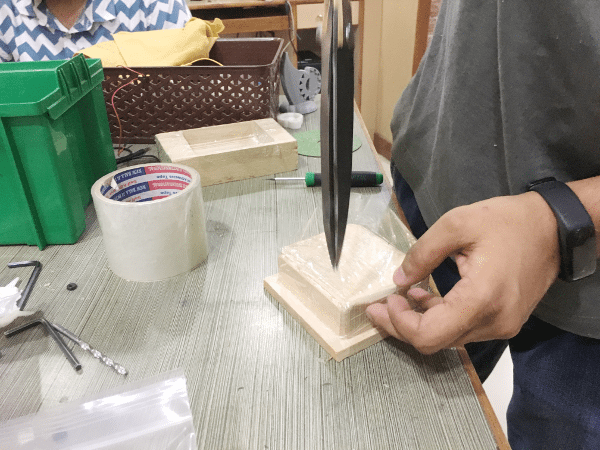
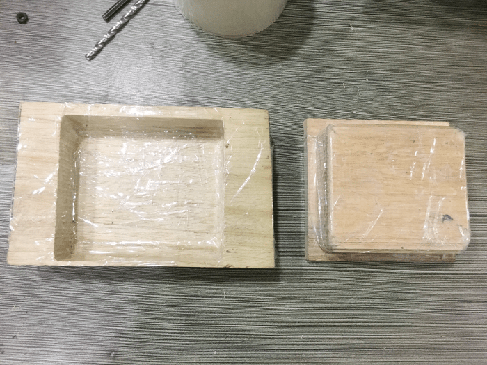


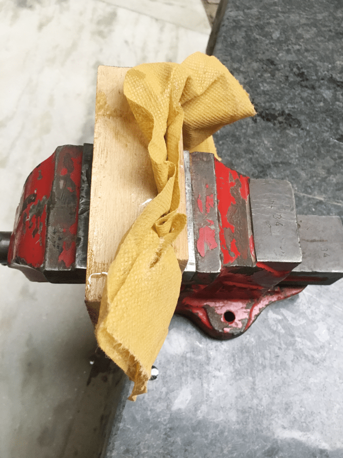
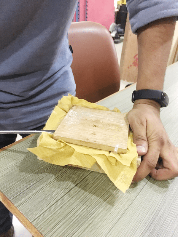
After 24 hrs